Hello, dear visitors of the site. This article presents a manufacturing option for the generator for the Tohatsu M5 outboard motor (5 hp). The specification for the motor (among other things) indicates:
- Generator - 12V ... (option).
That is, there is (provided) a place for the generator coil on the motor, and often the coil itself is not.
Now in water tourism, travel, fishing on a small boat (just an air bag), all kinds of gadgets are used (flashlights, cell phones, smartphones, navigators, echo sounders, etc.). And they are powered by autonomous power sources and often these are batteries. And there is a need to recharge them right on the road ... For this purpose, it is advisable to equip the outboard motor with a generator and related accessories. To have the desired DC voltage at the output.
Materials and tools for manufacturing the generator:
- strips of transformer iron from a plate transformer 0.35 mm (Fig. 2)
- mounting wire 0.5mm2
- winding wire PETV-2 0.56mm
- cambric
- 5 pin connectors (female and male)
- 4 M5 bolts with washers and M5 nuts
- 1.5 mm fiberglass (non-foamed)
- strip of varnish cloth
- Epoxy adhesive
- drill with drills
- file for metal
- metal scissors
- soldering iron with solder POS61, flux, tweezers
- emery, goggles
- vise, hammer, clamp
- ruler, scriber, barbell

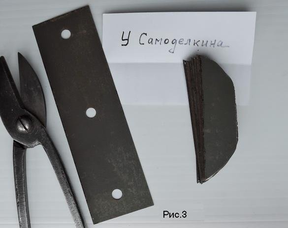
First, we cut the core blanks from the strips of transformer iron with scissors as in Fig. 3. With machining allowance.
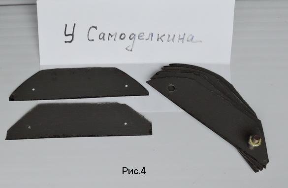
You can handle it in different ways, just keep in mind that the transformer iron is brittle and crumbles ... I previously drilled a recess for the winding and 2 base holes Fig. 4.
Then, having tightened a bag between steel profile plates (2 mm thick) Fig. 5, he turned the assembly on an emery.
And he finished, as usual, with a file, rounding the corners under the coil of the coil. The profile should be as in the drawing Fig. 6. With an allowance of + 0.2 ... 0.4 mm.
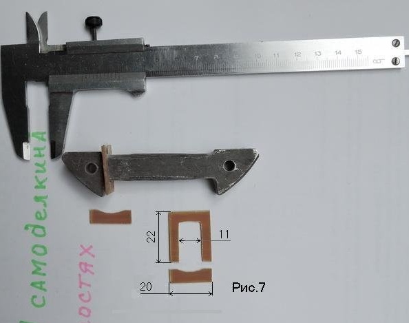
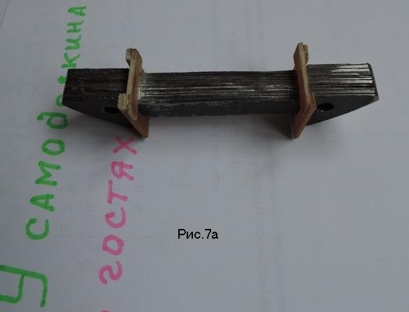
Then the preparation of the blanks of the cheeks of the coil. From PCB as in the drawing Fig. 7.
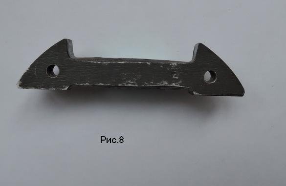
Then gluing with epoxy glue. Since my transformer plates were already varnished initially, gluing is done with a thin layer of liquid glue. Gluing (assembly) is carried out on 2 M5 guide screws.And you need to provide that the plates from the transformer do not stick to the screws. You can lubricate the screws and nuts with petroleum jelly and the like. After the epoxy is dried (24 hours), the package (core) is finished turning into a size (Fig. 8)
You can glue the cheeks with epoxy (or glue Moment), and fasten the clamp already directly on the core.
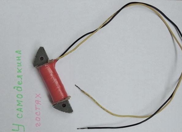
After drying, we glue the core between the cheeks with glue and wrap the cut strip of lacquer cloth 2 layers. And glue to not unwind. Solder the end of the PETV-2 winding wire to the mounting wire. We close it with cambric and we wind the actual winding of 244 turns. The end is also soldered to the mounting wire. The coil assembly is shown in Figure 10.
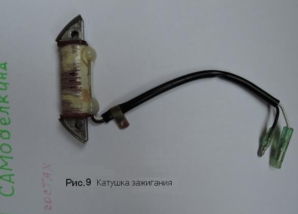
The standard ignition coil (for comparison) is shown in Fig. 9
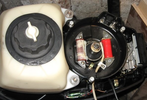
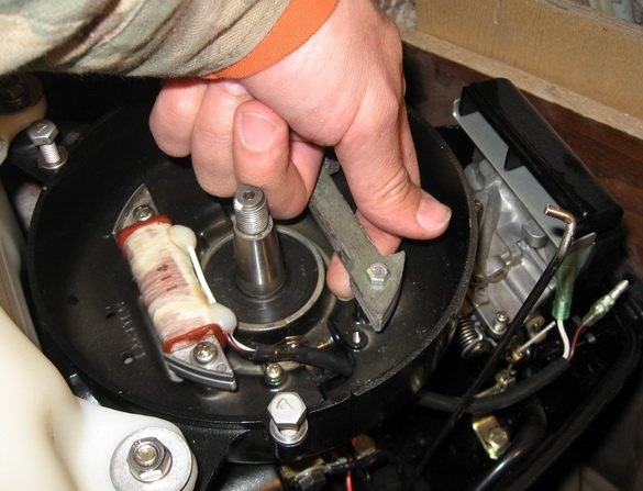
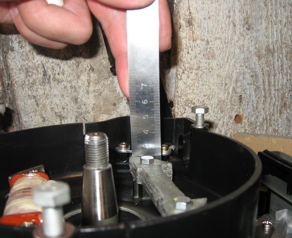
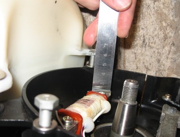
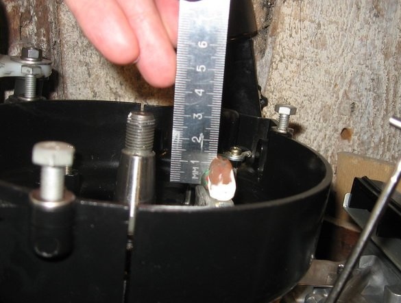
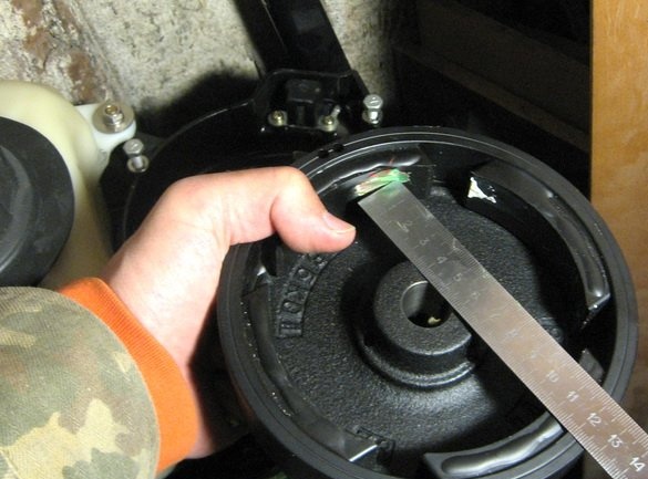
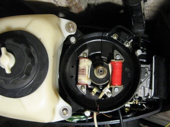
Reconnaissance at the installation location of the coil on the motor is shown in photo IMG_41xx
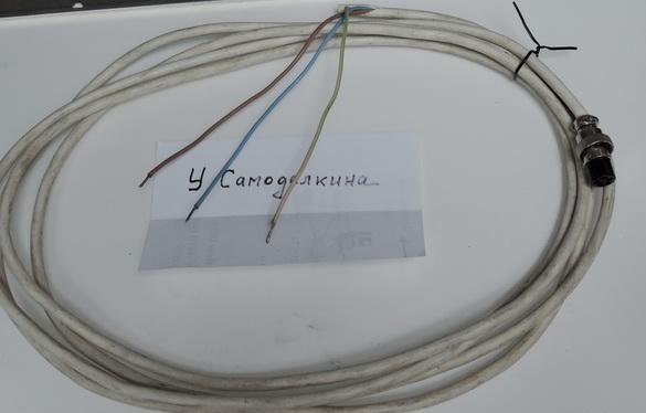
We install the coil under the flywheel opposite the standard (ignition), fasten with 2 M5 screws (Fig. 12). We put cambric on the mounting wires from the coil. And solder to the plug, which is mounted on the side wall of the pallet.
Test scrolling from a manual winding is shown in the video.
The lamp lights up even from scrolling by the plant. When starting the motor without voltage limiter and stabilizer, the bulb will burn out.
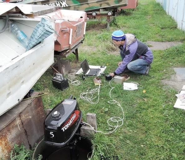
Fig. 13 shows a test measurement in a water barrel.