
Greetings the inhabitants of our site!
The author of YouTube channel “AKA KASYAN” wondered whether it is possible to assemble soldering station on the stings t12. The answer was found by the Chinese comrades, and they say that it is possible, they even have a temperature control circuit with maintaining power.
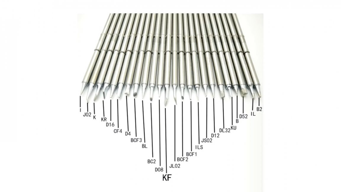
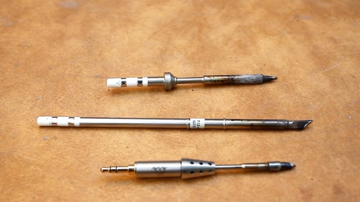
Of course, there are some nuances here, about which a little later. Stings t12 They have a lot of advantages, they are not expensive, they heat up instantly, they have many varieties of tips, they are durable and powerful enough. Therefore, stings of this type mega are popular.
Certainly in our time for quite adequate money can buy digital controller, stinger, handle, power supply and assemble the station from the finished modules.
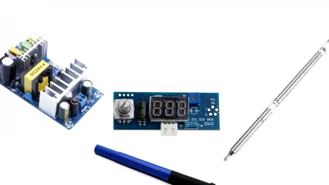
Can also buy all assembled, and you can spend a day and assemble an analog version, which will be almost nothing inferior to digital with PWM control.
Of course, the digital station on the microcontroller has much more functionality with a bunch of settings, and the soldering iron is generally equipped with a vibration sensor and an additional compensating temperature sensor. But as practice shows, quite often, in principle, no one uses most of these settings.
This instruction will be useful to those who want to have a simple station on t12 tips, but do not want to spend too much personal savings.
On the Internet, without much difficulty, you can find two circuits of analog temperature controllers for Nakko t12 tips.
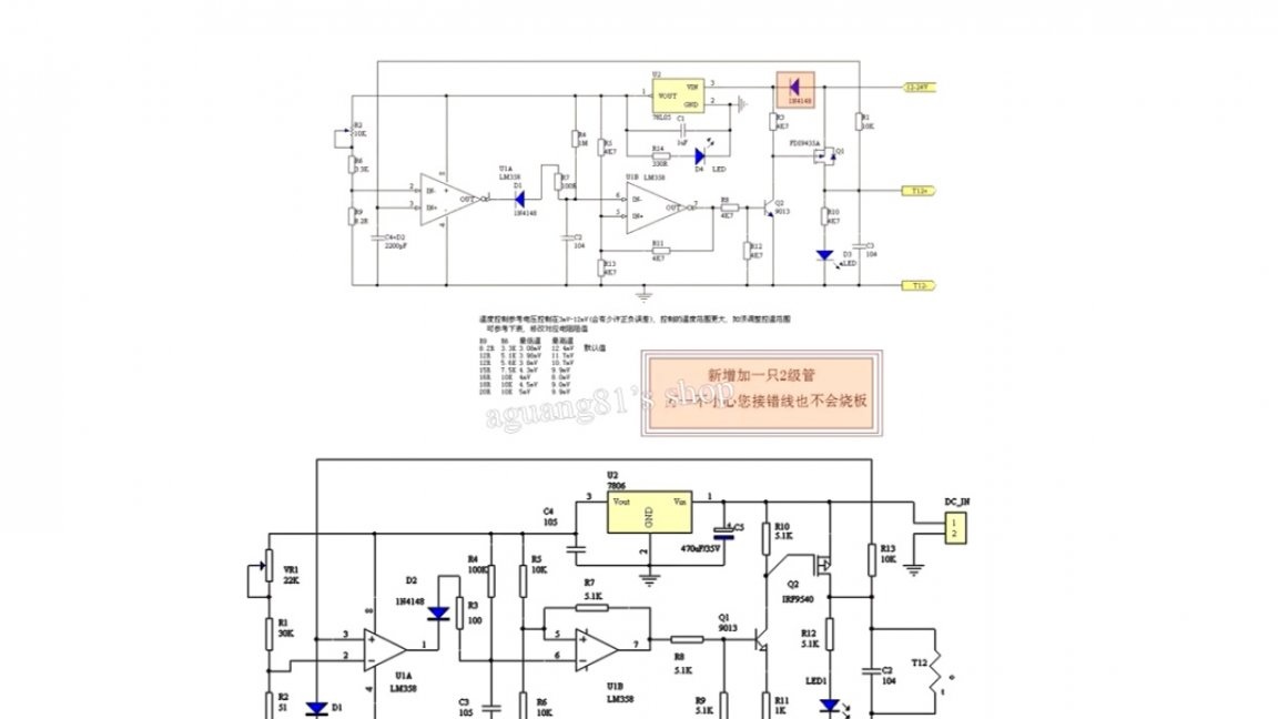
As you can see, there are no microcontrollers here, both thermostats are made on a dual operational amplifier. In conventional soldering irons, which are used in the same A936 stations, there are 4 main wires, 2 for a thermocouple and 2 for a heater.
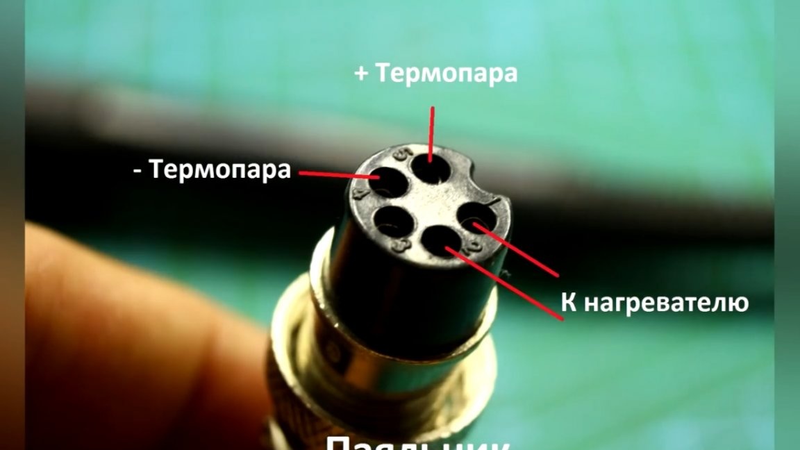
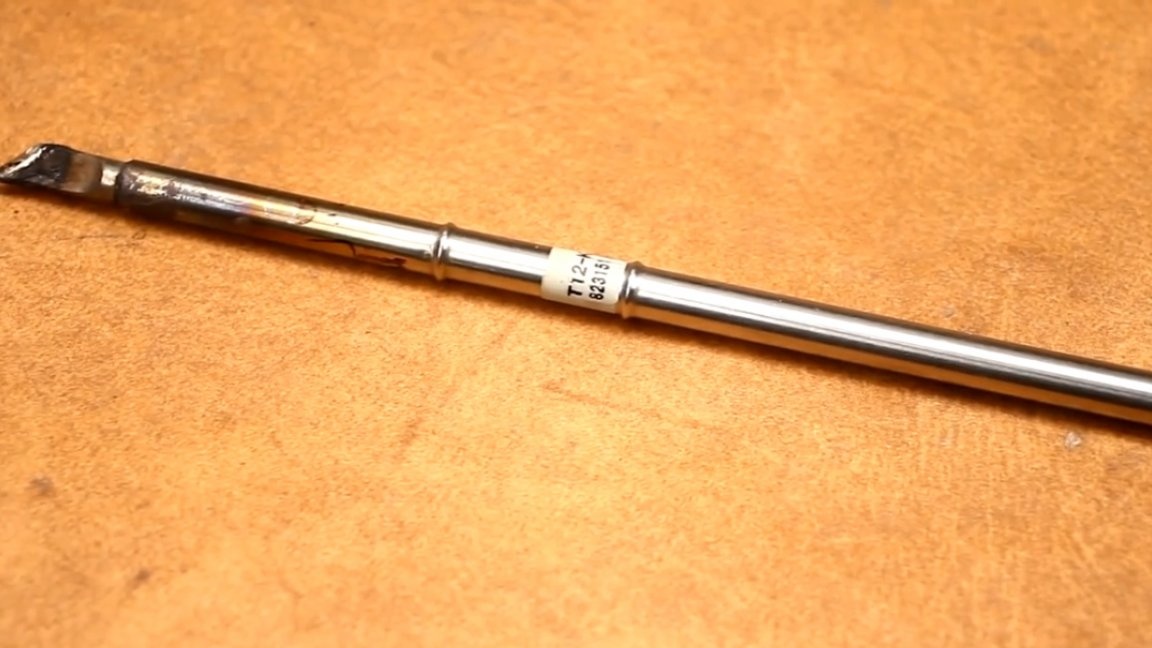
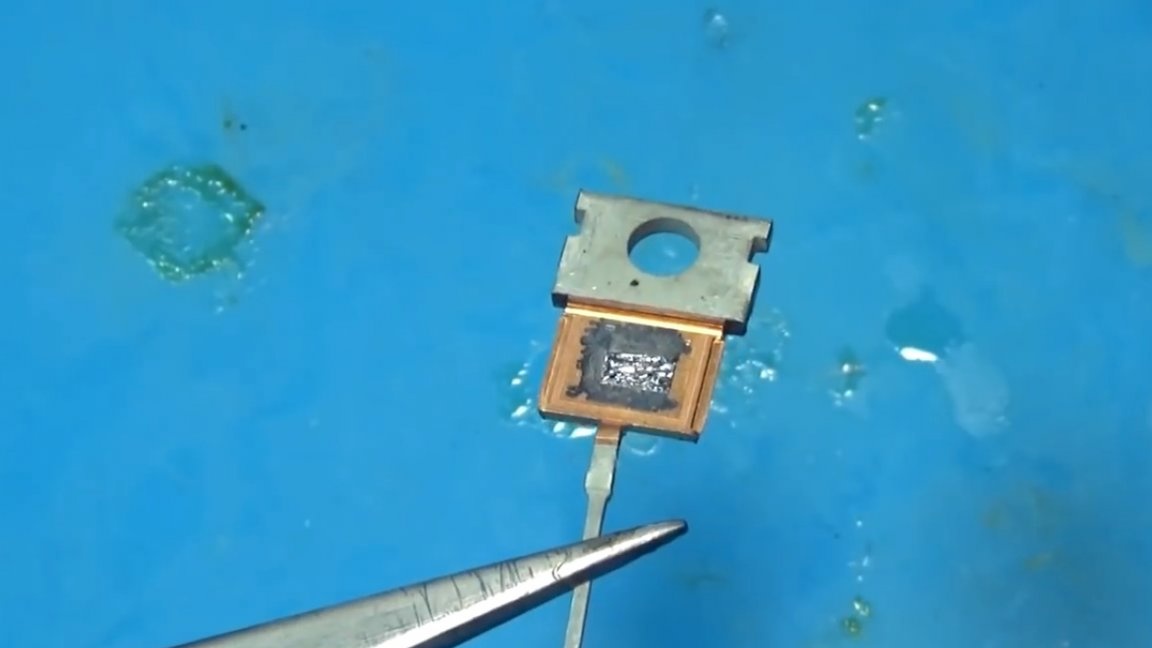
In the case of t12 stings, everything is a little different.
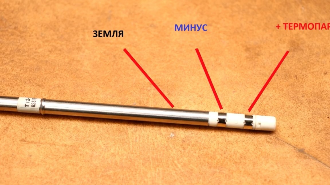
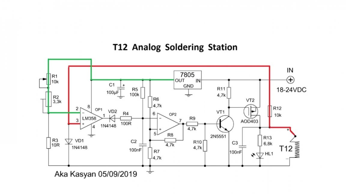
In this case, the thermocouple is connected in series with the heater. As a result, we have 2 main wires: plus (+) thermocouples and ground (-), well, and grounding (its author did not use it, but it is still advisable to ground the case).
The soldering tips of the TS100 and TS80 are arranged in exactly the same way, the thermocouple is in series with the heater, only the tip form factor is different. And for lovers of "perverting" it is worth saying that you can stick a t12 tip in the ts100 soldering iron, it is inconvenient, but cheap.
Let's get back to our scheme.
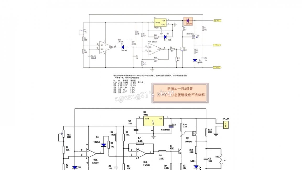
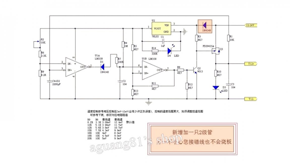
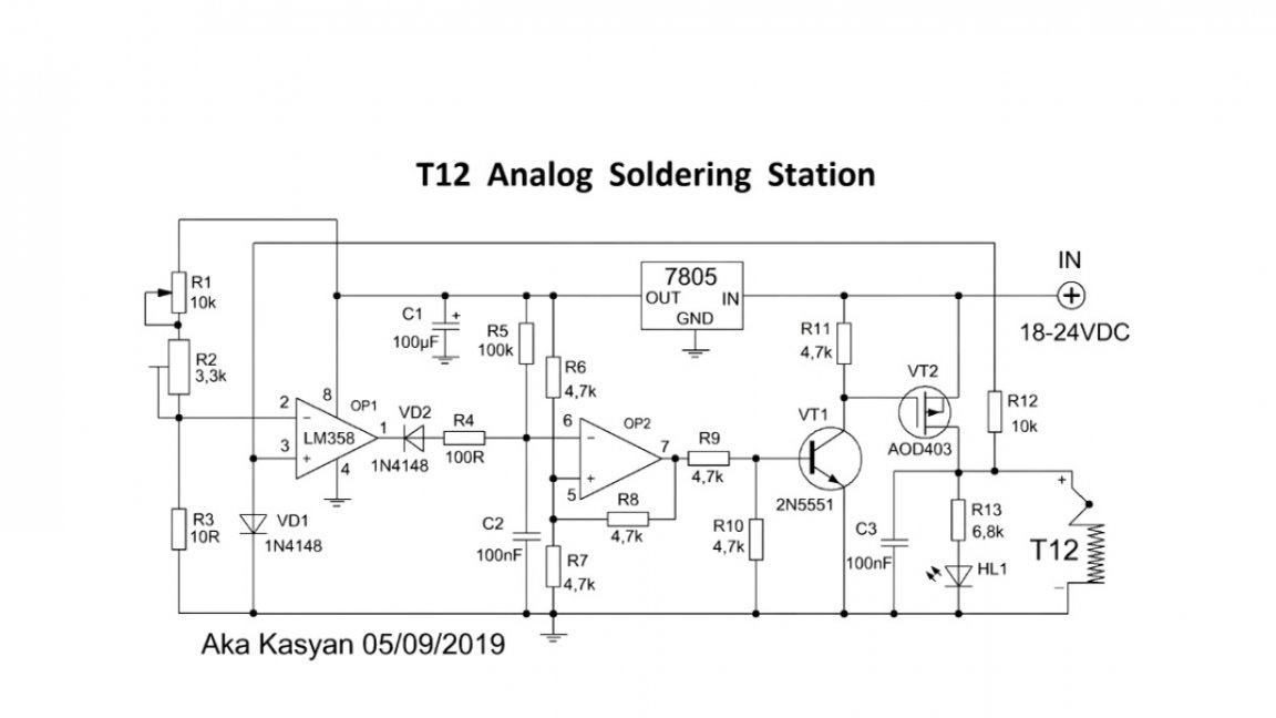
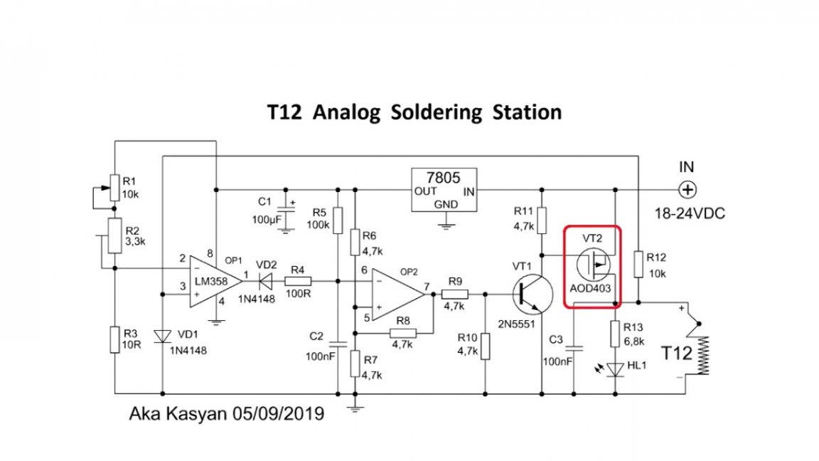
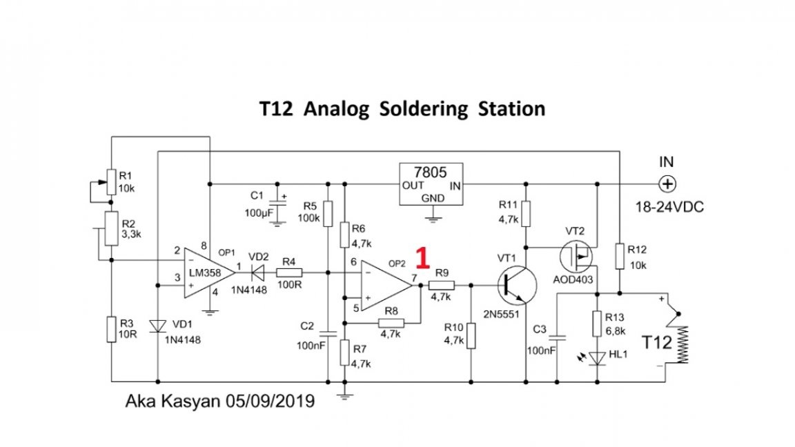
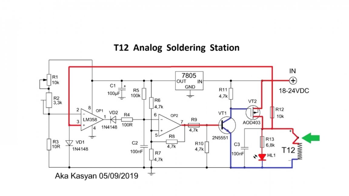
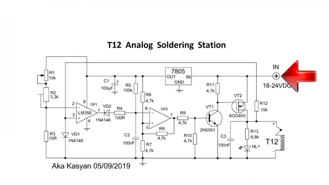
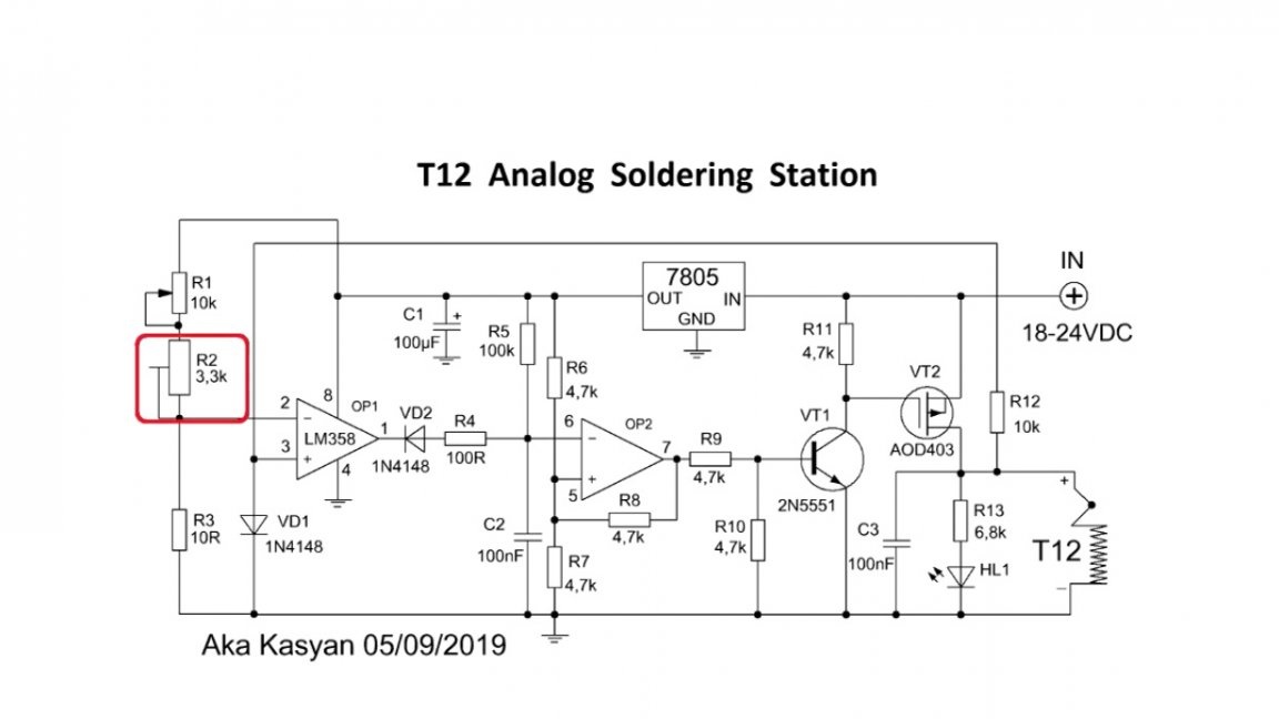
Of these 2 schemes, the third was obtained, it is now in front of you:
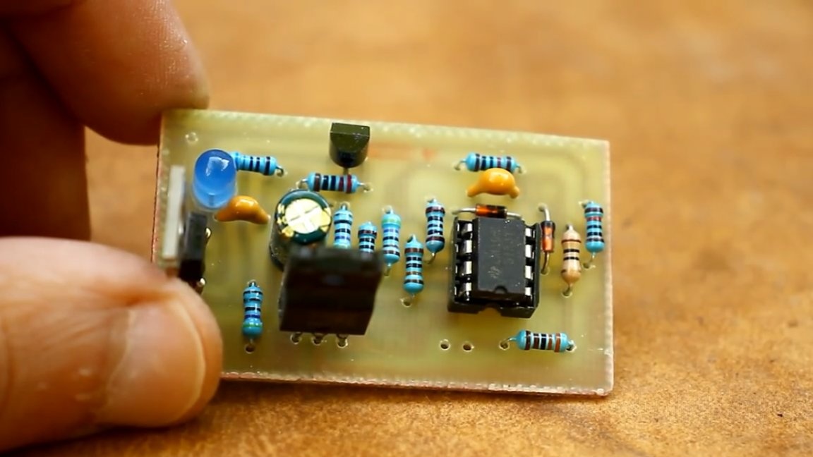
It is worth noting that each of the above schemes is fully operational.The author simply adjusted the third option, as it were, to his needs, here those components that were at hand at the moment were used to a greater extent.
In this case, switching is carried out by the plus (+) power, therefore, a p-channel field effect transistor is involved here.
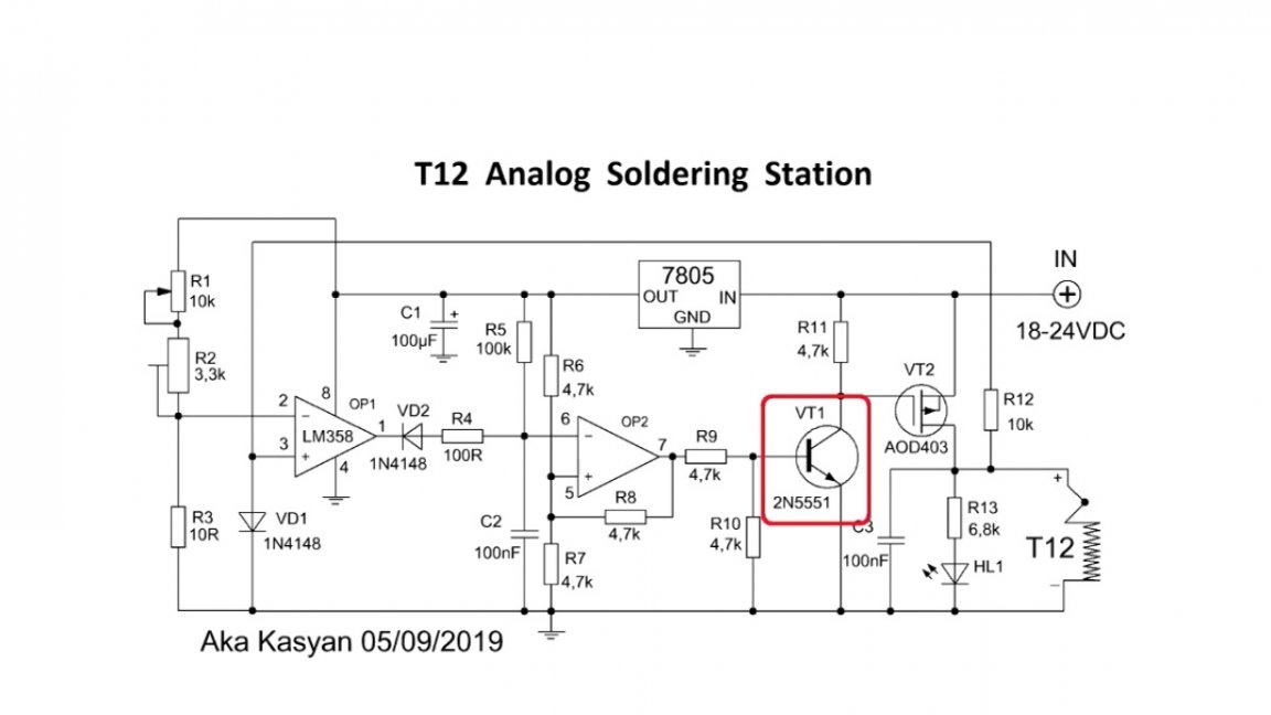
This transistor is controlled by a low-power bipolar transistor, which is also an inverter for compatibility.
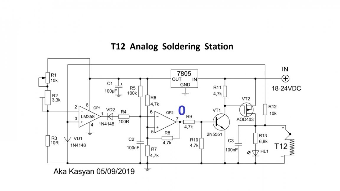
In a nutshell about the principle of operation of the presented scheme. An operational amplifier monitors the voltage coming from the thermocouple and compares it with the reference voltage.
Based on this, the output of the operational amplifier is set to "0" or "1".
A unit triggers a low power transistor. Opening it supplies voltage to the gate of the power transistor, as a result of which it is triggered.
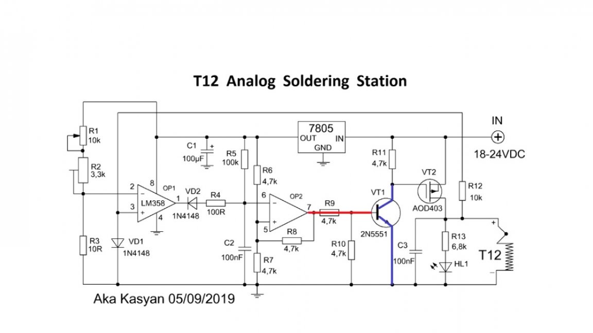
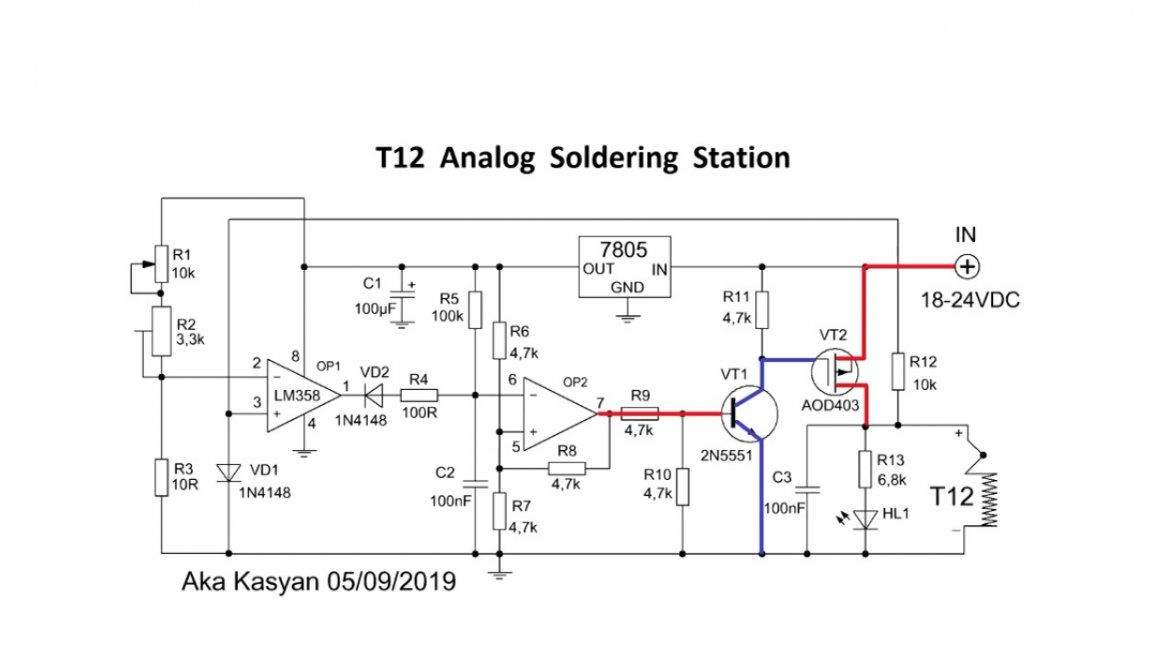
Through the open channel of the power transistor, power is supplied to the heater and heating begins. At the same time, the LED lights up, which acts as an indicator.
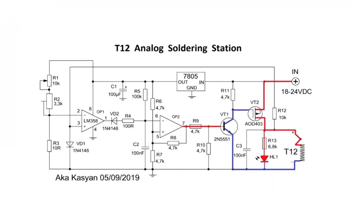
When heating, the voltage from the thermocouple will increase, the operational amplifier monitors this, and when the voltage from the thermocouple is above the set threshold, the transistors will close, the LED will go out and the heating will stop.
Such cyclic switching occurs rather quickly, due to this, the set temperature value is maintained at the tip of the soldering station.
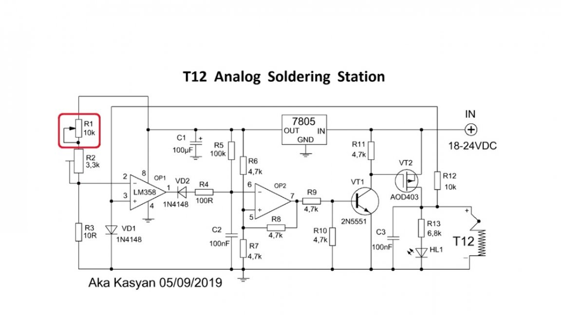
The temperature is adjusted by changing the reference voltage. To change it, you must rotate the variable resistor.
The reference voltage itself forms a 5V linear stabilizer, while an operational amplifier is powered from it.
Due to the fact that the field effect transistor operates in a key mode, it practically does not heat up and in this case, in principle, you can do without a heat sink.
The soldering station will respond to temperature changes quickly enough. This is due to the fact that the thermocouple t12 stings located very close to the tip. Therefore, with the t12th sting, the presented simple analog circuit will work much better than with soldering irons where there is a separate thermocouple.
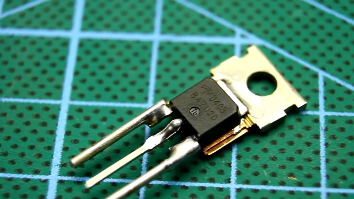
There may be problems with the p-channel transistor. Although if you have a radio parts store nearby, you can just go and buy the appropriate transistor. The author of this homemade product does not have such an opportunity, so the transistor was borrowed from the protection board for lithium-ion batteries.
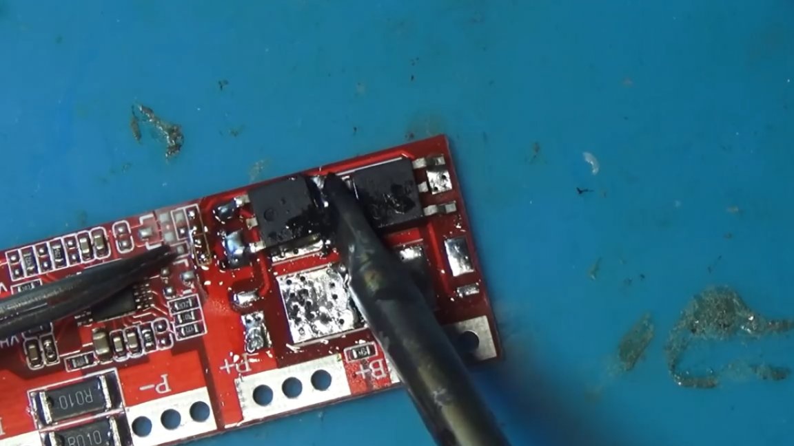
On such boards installed p-channel transistors AOD403.
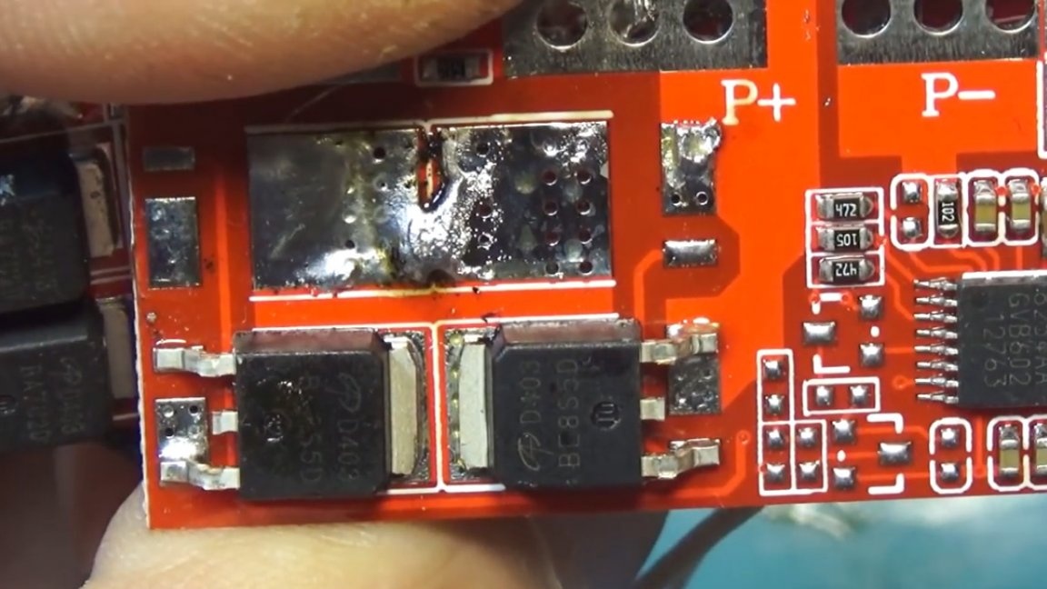
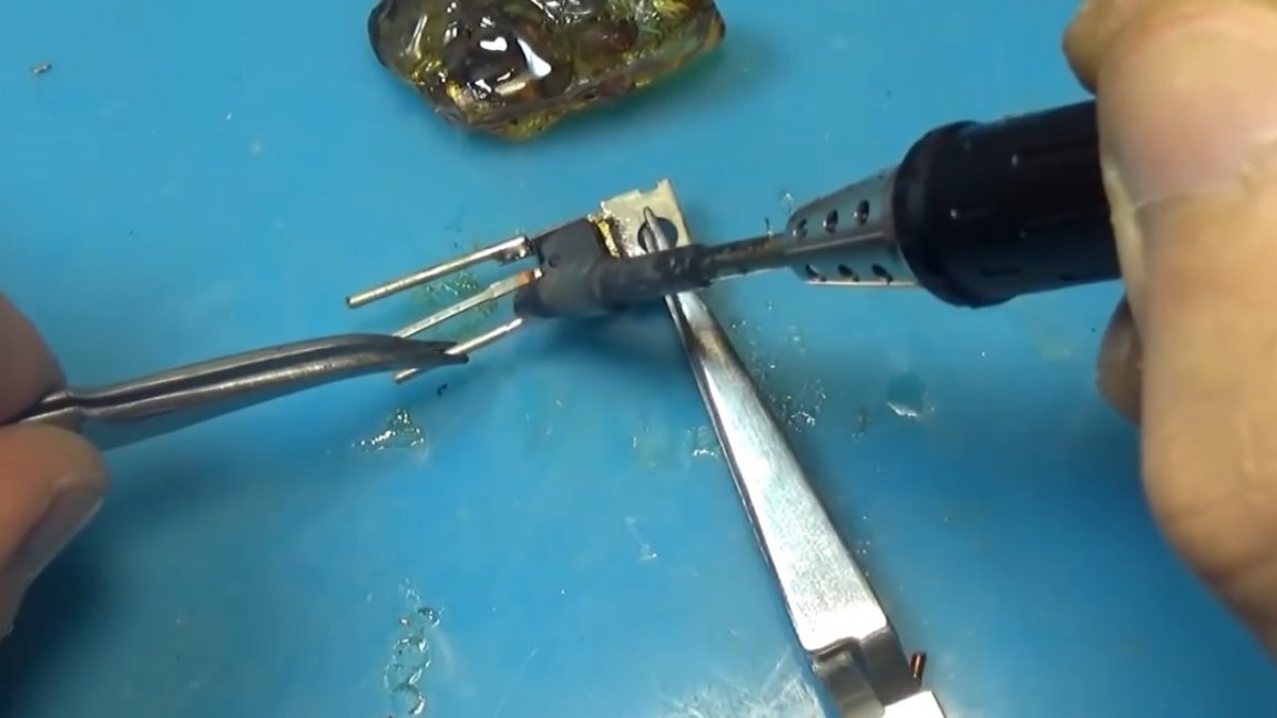
These are pretty good transistors, but my board is designed to install a transistor in the TO-220 package, and this instance is in the TO-252 package, so I’ll have to resort to “techno-distortion” once again.
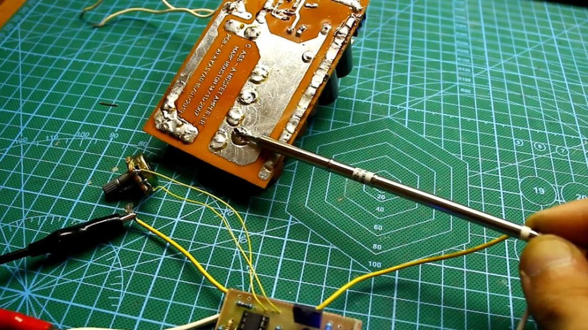
Calibration First of all, it is necessary to apply a constant voltage to the circuit in the range from 18 to 24 Volts (preferably 20V). At this point, the tuning resistor is in the minimum position.
The variable resistor is twisted to maximum.
Next, we take a thermometer and measure the temperature at the tip of the tip after it has completely warmed up.
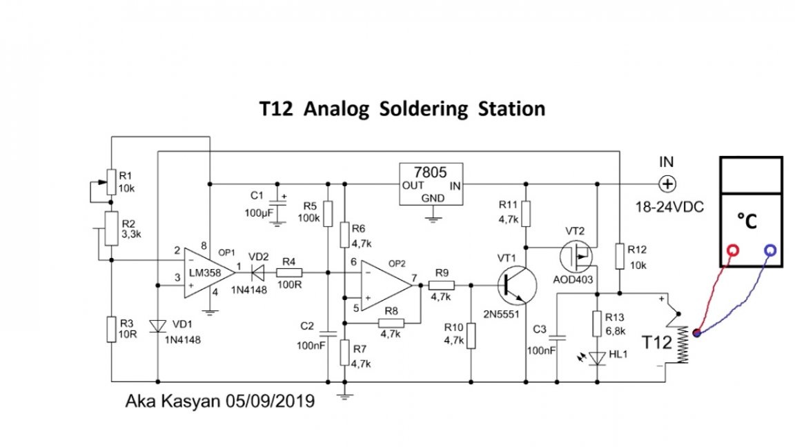
If the temperature is less than 450 ° C, by slowly rotating the tuning resistor we obtain the required temperature.
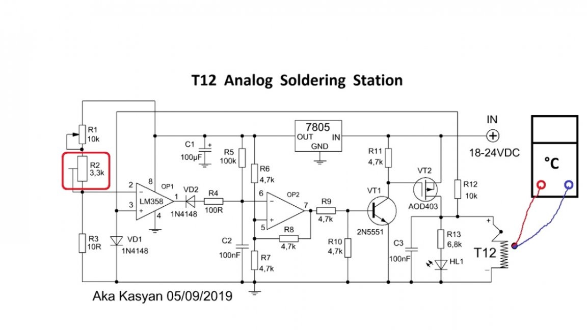
Then, after tuning and calibration, the tuning resistor can be replaced with a permanent resistor.
As for the maximum temperature of 450 ° C, it is up to you to decide. The limit can be made even 480 ° C, but even 400 ° C will be enough.
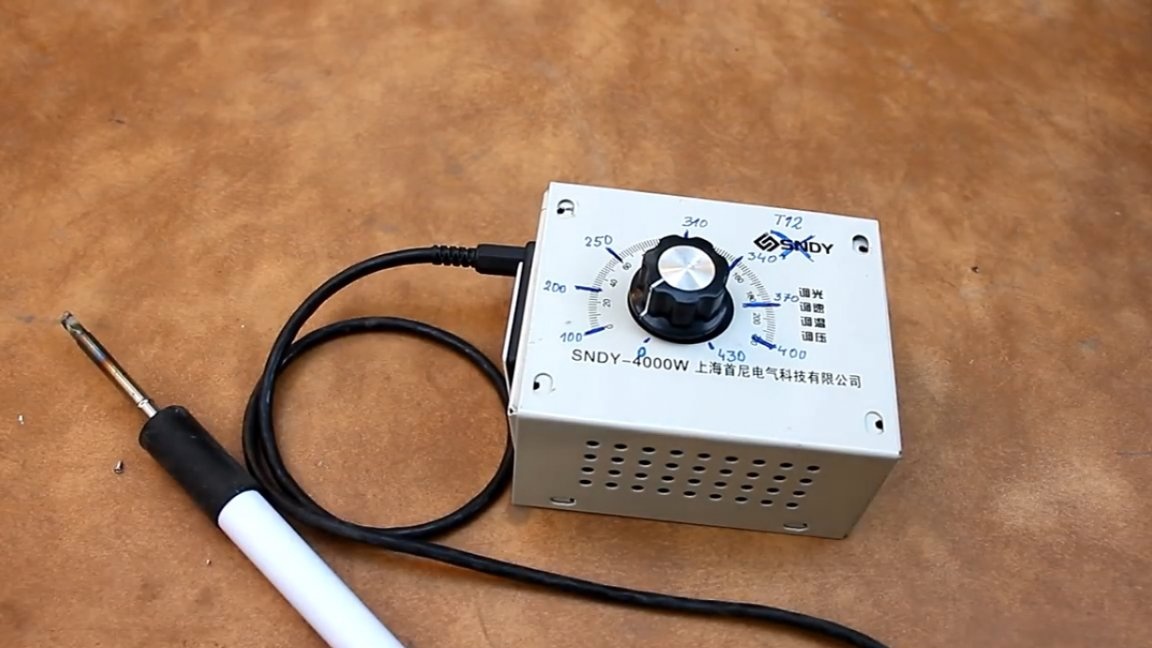
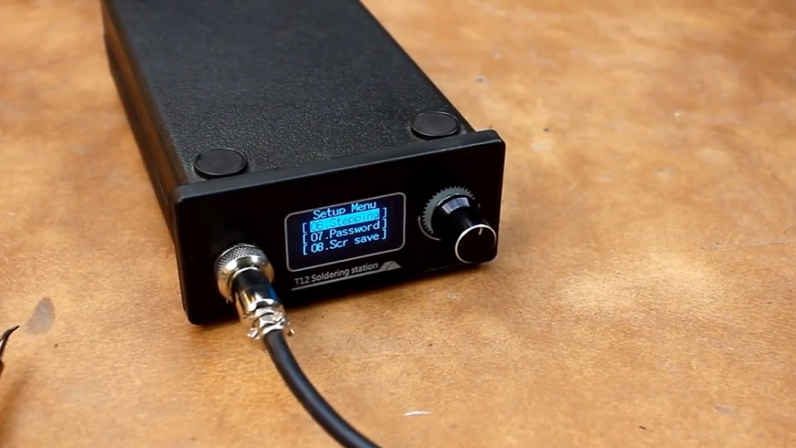
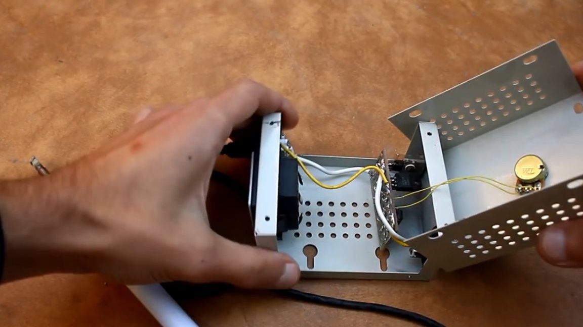
Next, install the circuit in the housing.
After that it is necessary to make an analog scale. To do this, put the variable resistor in the minimum position, make a mark, record the obtained temperature value and do the same for different positions of the variable resistor.
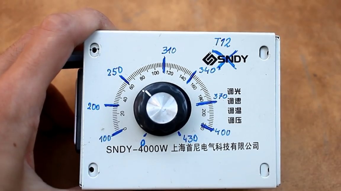
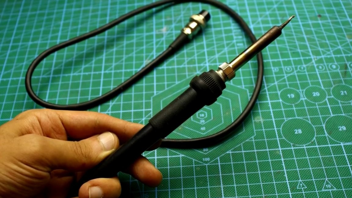
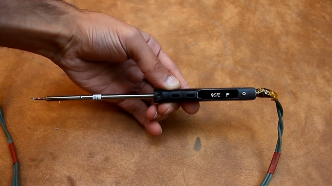
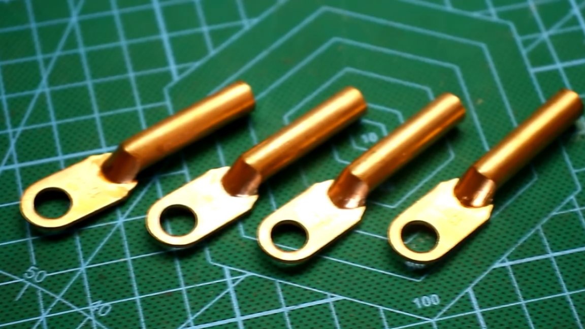
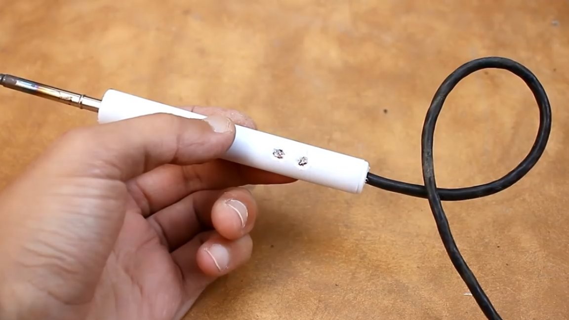
The regulator is completely ready and works perfectly, but to solder with a bare sting, to put it mildly, is not very comfortable.The next step is to make a more or less presentable handle for it. For its manufacture, we need: an old marker, a shaft from an old printer, or rather, such rubber bands from it:
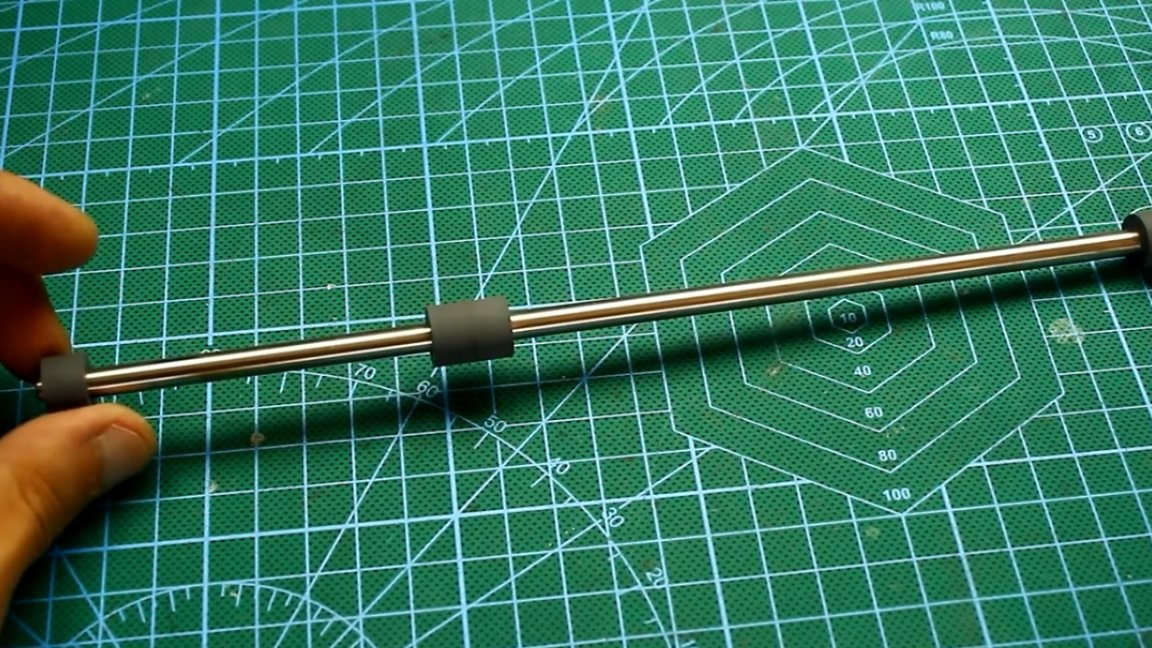
These gums are useful to us for fixing the sting. It is also necessary to find / buy these copper terminals with an inner diameter of 5 mm:
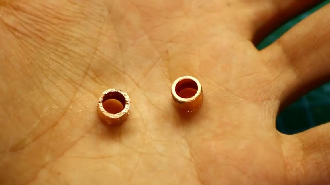
As the next step, we take a hacksaw and reciprocating movements we get a pair of these sleeves with a height of 6 mm:
Then we take a piece of PCB, we tin and solder on it the previously obtained terminals and a copper plate, which acts as a limiter.
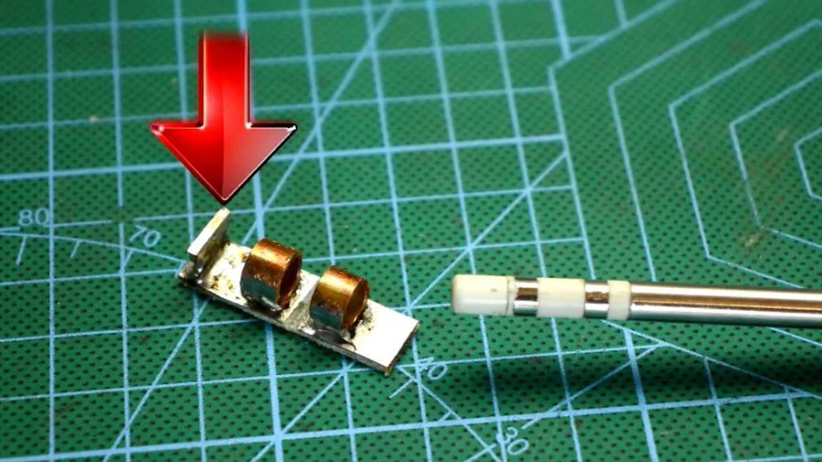
The distance between the sleeves is 6mm. If you install a sting in such a t12 blank, then the contacts will be right in the sleeves.
Do not forget to remove the foil from the PCB between the sleeves:
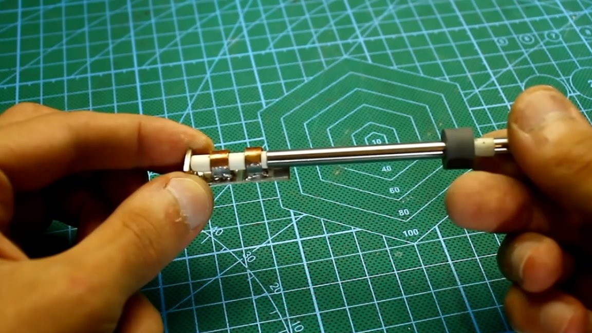
Then in the sleeves it is necessary to make holes and cut the thread into which the screws will be screwed. We will have them as a fixative.
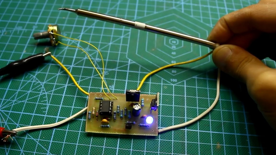
Next, solder the cord, check the soldering iron for operability, then push the whole thing into the case from the marker and fix the components with epoxy.
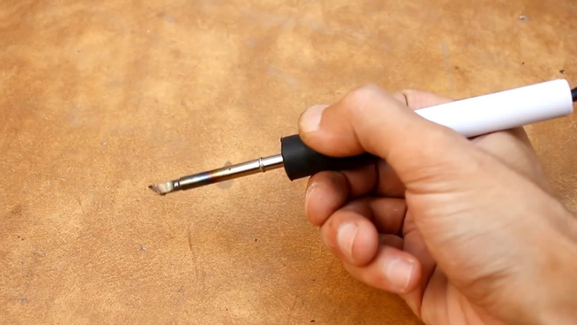
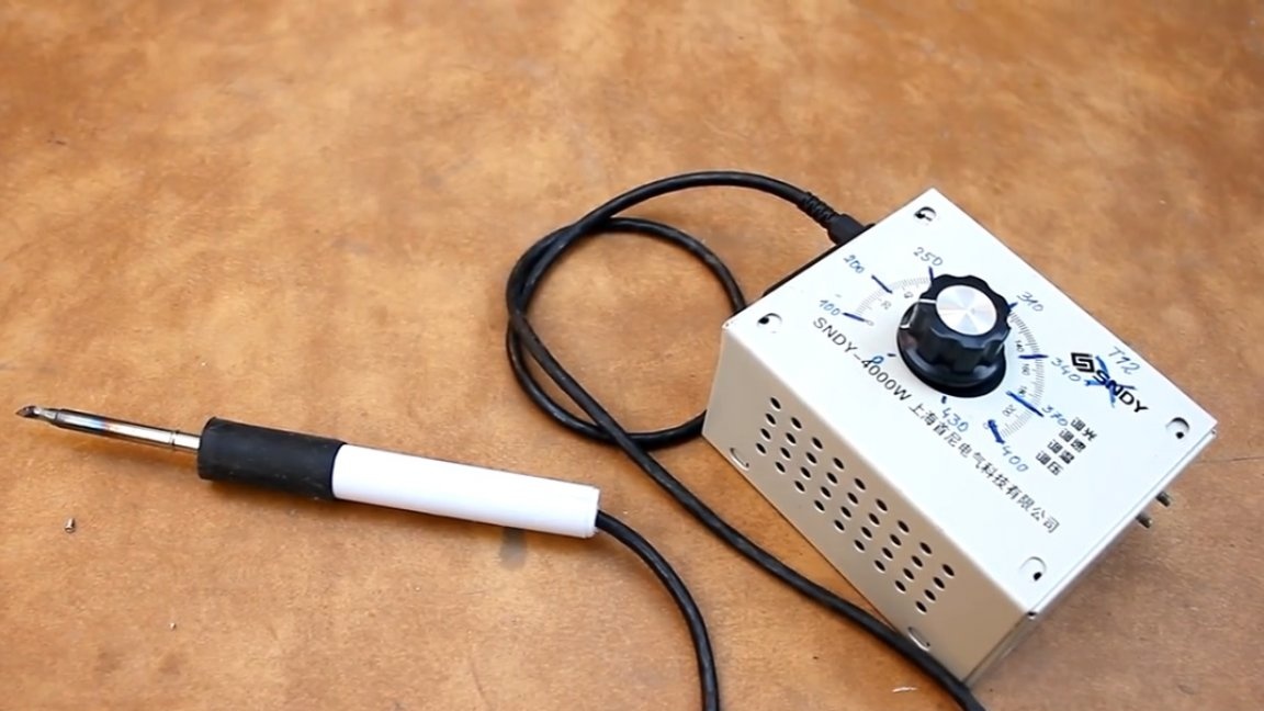
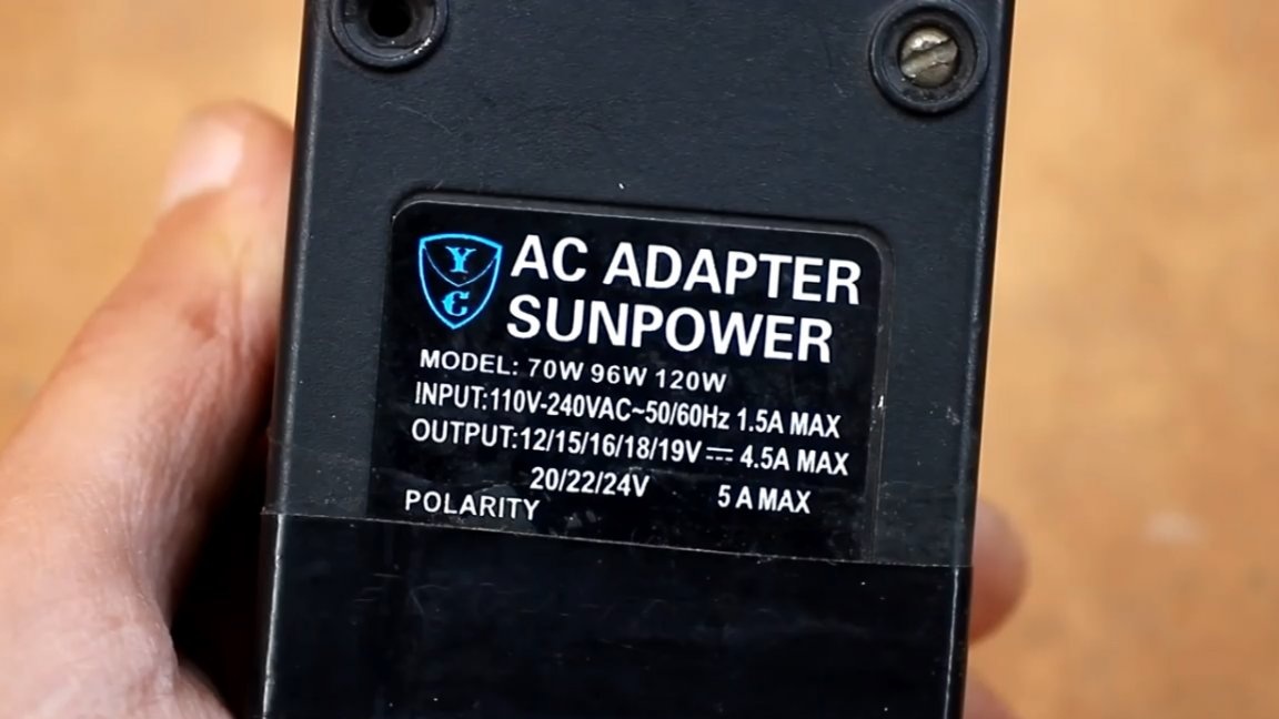
There is no power supply in the case, and the whole structure is powered by an external 24V adapter.
Here is a soldering station in the end turned out. That's all. Thank you for attention. See you soon!
Author's video: