Greetings the inhabitants of our site!
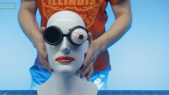
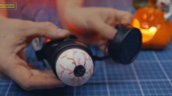
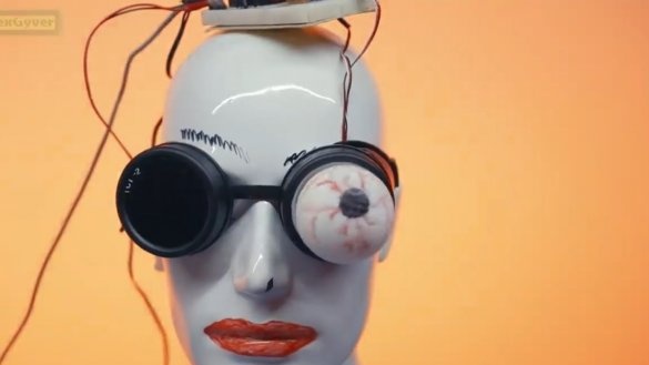
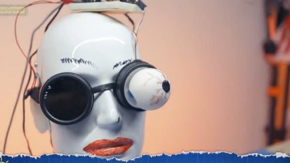
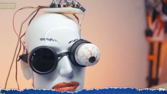
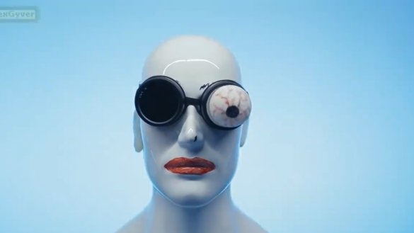
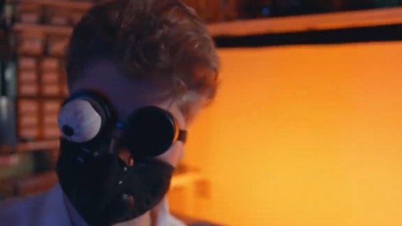
This time AlexGyver, the author of the YouTube channel of the same name, about the holiday, which, incidentally, we don’t really like, decided to repeat Adafruit project - a bionic eye that is inserted into the glasses of a gas welder.
From the point of view of the code, this finished project is absolutely not interesting, the author was interested in the mechanism, namely, its coordinate system.
We will return to this, but a little later, but first, let's collect all the mechanics and connect everything electronic Components.
To repeat this project you will need:
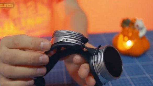
1) Gas welder glasses. You can use both metal and plastic.
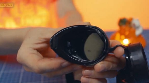
Plastic certainly fit better, but of course they cannot boast of quality. Specifically, in this instance, made of plastic, the sides literally fell off right away and the author had to glue them.
Such glasses can be purchased at the store selling tools or building materials. The author bought these in the All Instruments store.
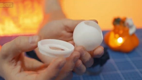
2) Next we need these printed on 3D printer spare parts.
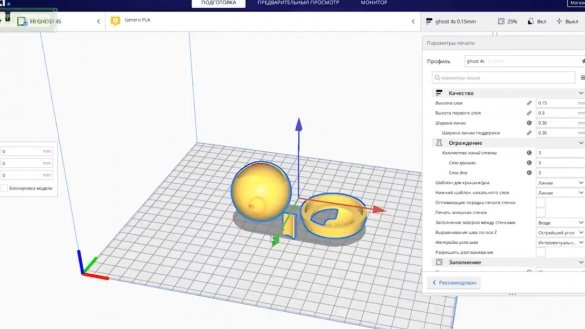
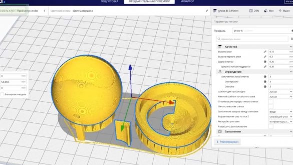
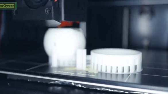
The author printed the elements with white PLA plastic on the new 32-bit flyingbear ghost 4s 3D printer. File contains all 3 models at once. Printing is necessary with supports.
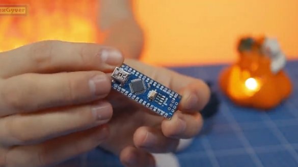
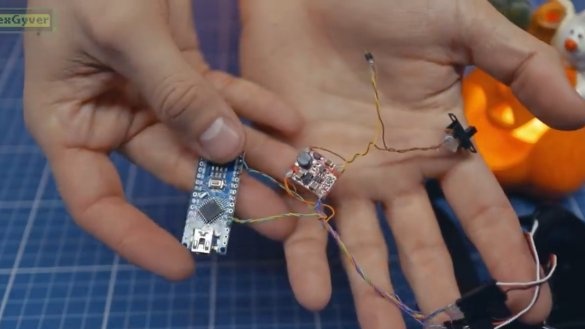
3) The next component needed for our Halloween special project is the platform Arduino Nano Models.
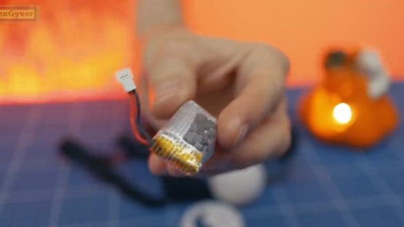
4) Also required lithium ion battery:
5) Boost dc-dc (up to 5V) converter;
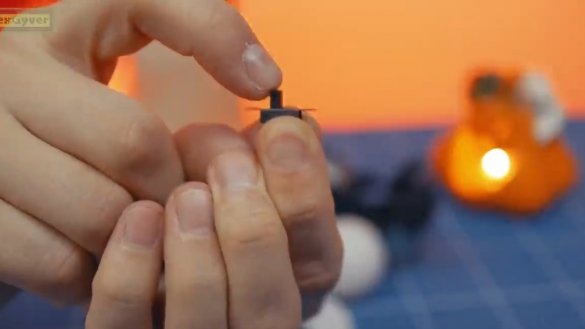
6) Switch:
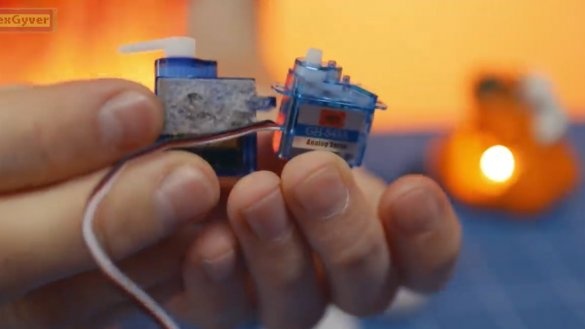
7) Micro servos, but not standard 9 grams, but even less:
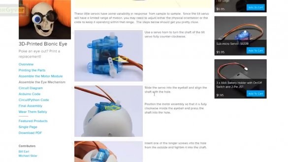
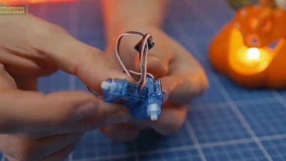
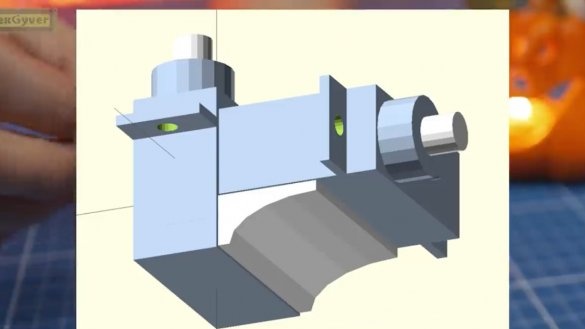
So, with the necessary components, sort of figured out, let's get down to assembling the device. First, we need to mount the drives as follows:
Here is a more understandable picture:
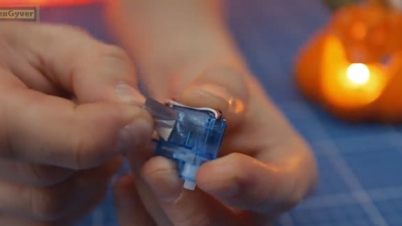
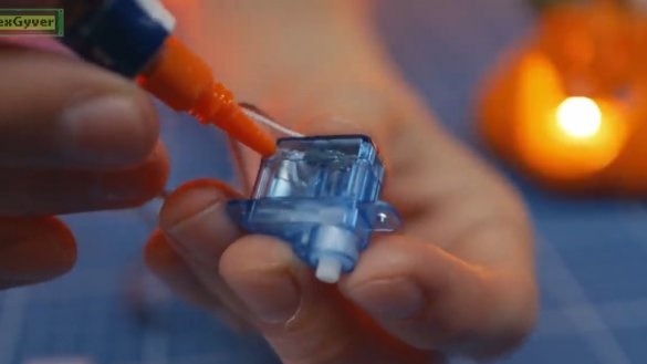
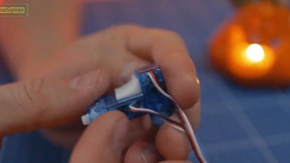
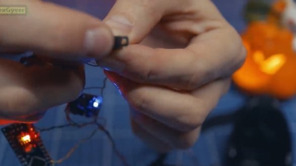
We remove the sticker, and with the help of superglue we connect this whole thing.
By the way, Chinese servos seem to be slightly different from Adafruth ones, and you need to glue them like this, with a little offset:
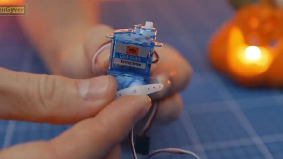
Ears must be removed, they will interfere.
Then to the lower drive, we hook the rocker and turn the shaft counterclockwise.
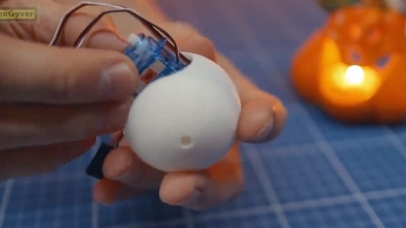
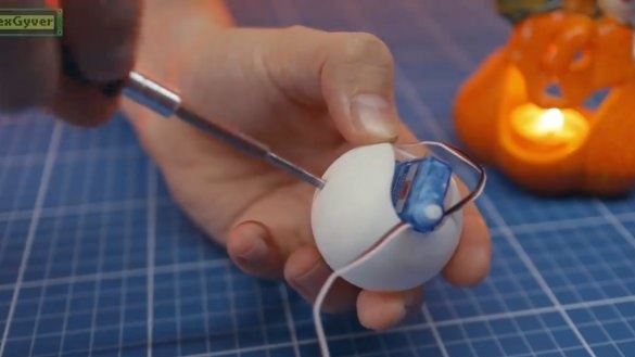
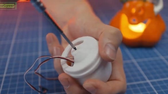
Insert the servos into the pre-printed on 3D printer blank (eye).
We rest the protruding drive to the very edge, and insert the output shaft into the hole inside the eye.
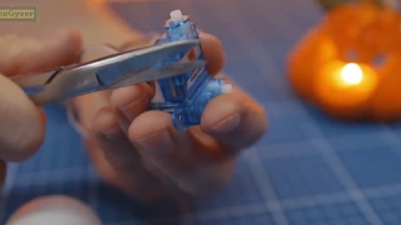
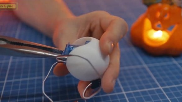
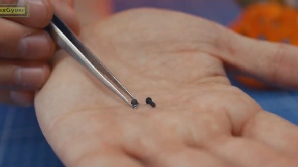
The long complete screw needs to be shortened a little. This can be done using nippers.
Next, with the help of a shortened screw, we fix the internal drive.
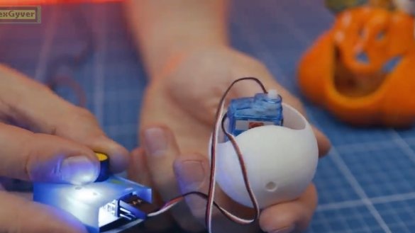
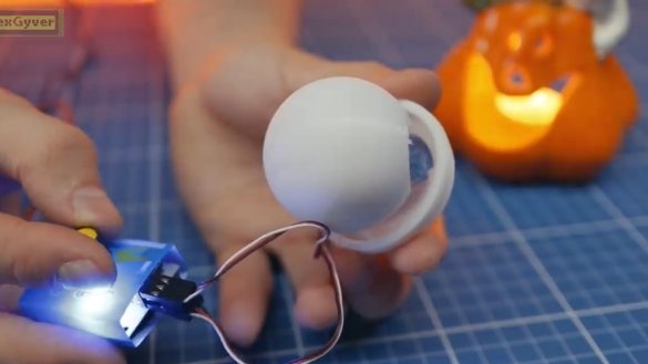
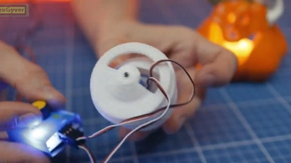
If you have a servo tester, you can verify the operability of the resulting mechanism.
Then we attach the second part of the eye to the shaft of the second drive and also fasten it.
We are convinced of the overall performance (should work together).
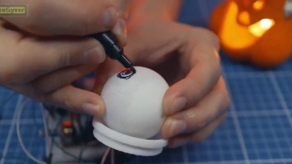
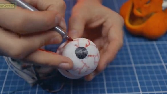
Especially for this project, the author wrote a simple code that smoothly rotates the drives at a random angle. But the center of the eye was slightly biased, so we find the actual center and draw the pupil.
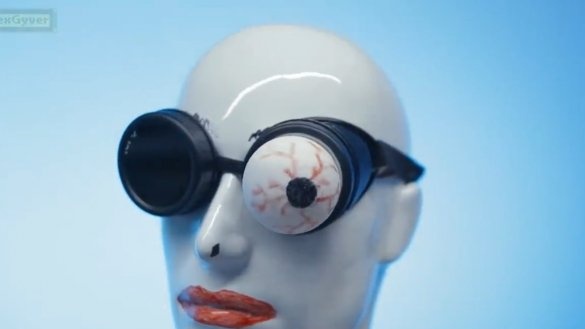
Well, since this is a holiday project, and the holiday is quite specific, then let's make it a little more terrible.
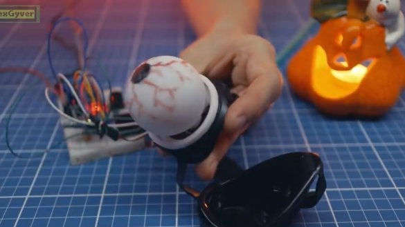
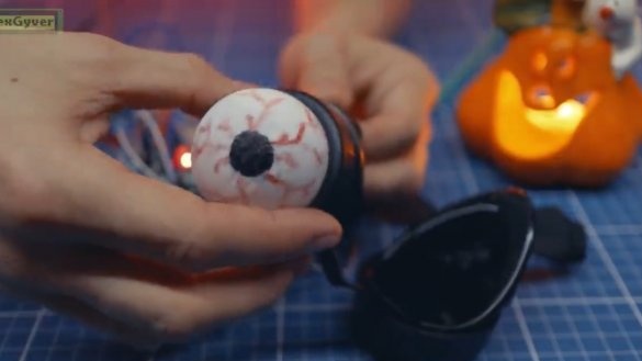
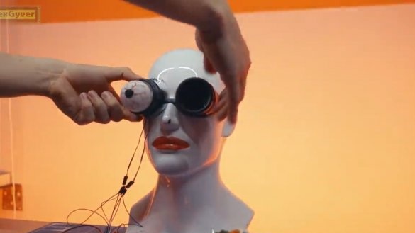
Next, insert the resulting part into the glasses.
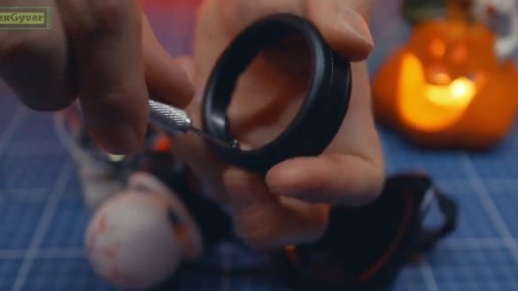
If it is not inserted, it is necessary to chamfer a little.
Then we put everything together.
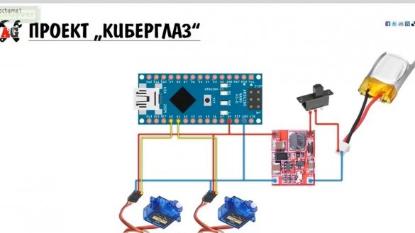
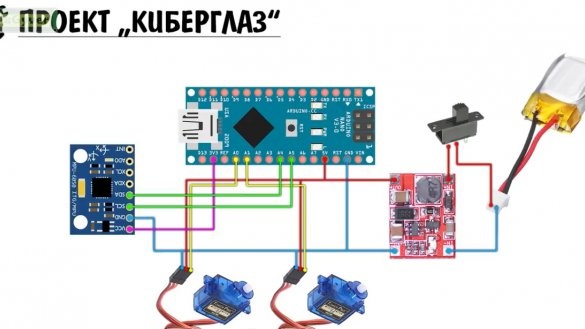
Next, we connect all components according to the following scheme:
Everything is ready, but now we have every drive just rises to a random angle, and in principle you can leave it like that.
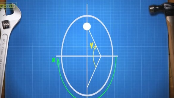
But remember at the beginning of the article was mentioned about the mechanism and coordinate system? So, the mechanism rotates along two axes, but not along those along which the human eye rotates. Our goal is to make such a mechanism behave exactly like the human eye. At first glance this seems impossible, but you can try to bring its coordinate system to normal so that you can put the pupil in any desired position.
So, we have two angles, we denote them by X and Y.
Y is the small angle of the eye, and X is the angle of rotation of the eye by 180 degrees.
To achieve all possible positions it is necessary to control both angles, and there is a specificity. Let's start with the simplest - circular motion with a maximum radius.
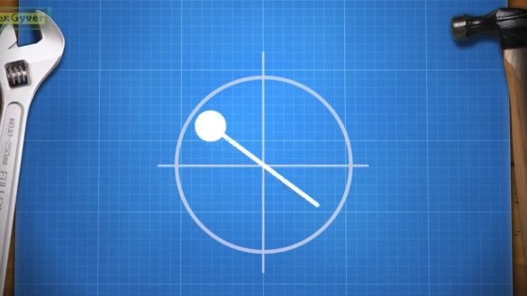
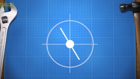
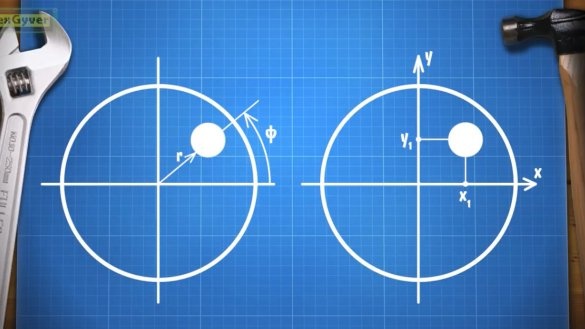
But it’s not so simple as it seemed. Therefore, the first thing the author did was a polar coordinate system in which you can set the angle of rotation of the eye and radius, that is, the removal of the pupil from the central point 00.
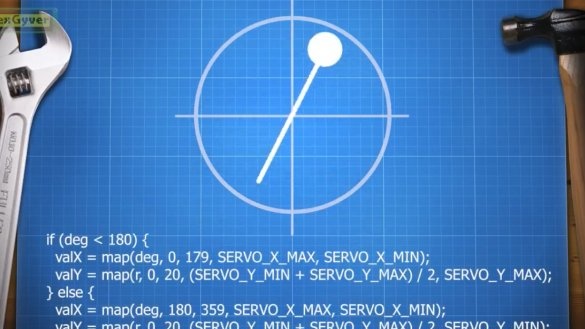
In the upper semicircle, we work from half the angle Y to its maximum value, and in the lower - from minimum to half. Now the eye movement can be programmed in a more interesting way. The movements themselves are random, but already around the circumference.
Now let's solder all the electronics, everything is as in the diagram:
Trying to turn it on.
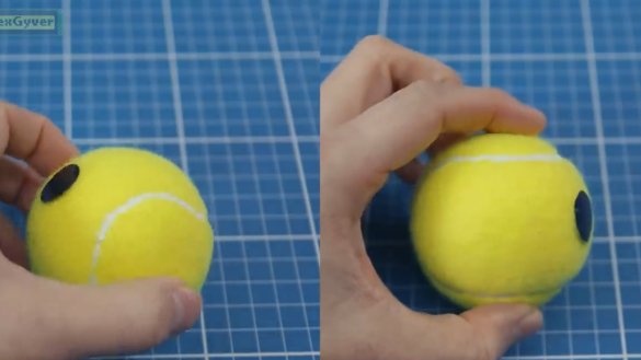
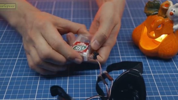
Indication is. Now we are hiding this whole thing in some kind of building (in this case, the author used a box from under “tick-tock”).
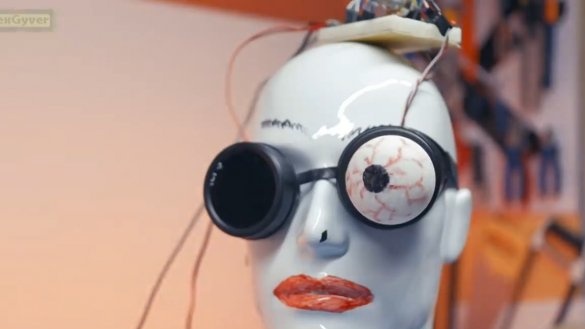
All of our cyber eyes are ready. Here is such a joke.
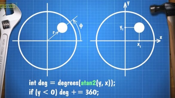
But let's still continue our theoretical research and translate the polar coordinate system into a Cartesian one, later I will understand why.
Everything is simple here, the atan2 function will help us, which returns the angle in radians from –P to P, and the hypot function, which will calculate the length of the hypotenuse in the same two coordinates, and the hypotenuse is the radius for our previous function.
And in such a simple way, our experimental subject can now turn his eye exactly to where we need (up, down, right, left).
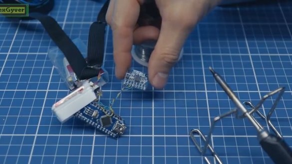
So why is this needed? This is necessary in order to be able to add gyroscopewith the help of which the eye will turn in the same direction as the head, which will probably look rather funny. Actually, the project was added gyroscope mpu6050, this is how it looks in the diagram:
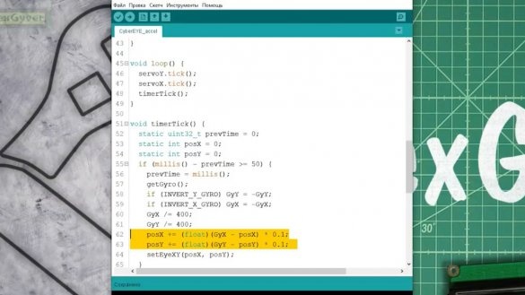
Change the code, make sure that the readings from the gyroscope deflect the eye. Through the filter naturally.
So what do we get in the end? The eye is a little late behind the turn of the head, thereby creating the effect that it turns right and looks at you. As a result, here is such a little mathematical project.
Firmware HERE. Thank you for attention. See you soon!
Author's video:

