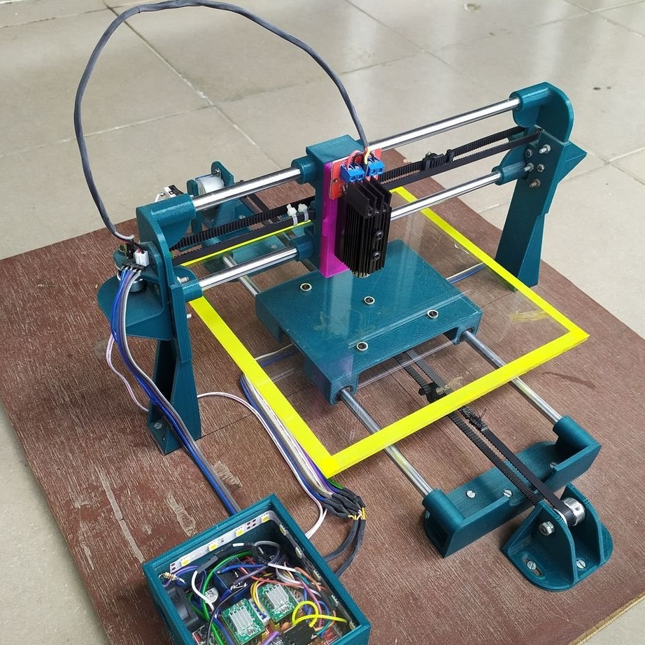
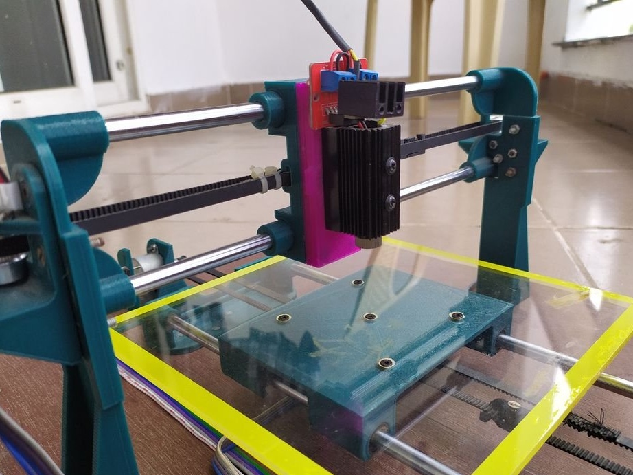
Looking through laser engravers on aliexpress, the master came across several USB-powered models. It was amazing that they could engrave on different materials, as well as cut shapes and patterns from stickers and paper, and do all this power from 5V USB. But the drawback of these engravers was that they had a small working area, in most cases only 40 mm x 40 mm.
Then the master decided to independently design and manufacture an engraver using a 3D printer for manufacturing. Along the way, he decided to make the laser holder modular so that the laser could be easily replaced with a pen or marker. A Bluetooth connection function has also been added.
Technical specifications of the engraver are as follows:
- Working area 200 x 162 mm
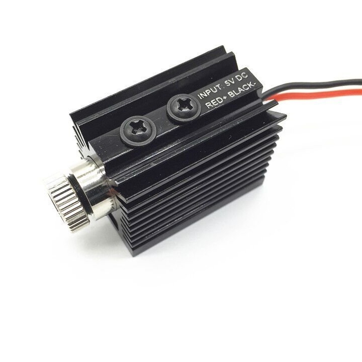
-1000 mw laser module
-Works from a USB power source (5V)
-Auto guidance function
- Bluetooth communication between laser engraver and PC
- PWM laser control. (Helps in creating different shades of black when engraving portraits)
-102.4 steps per mm resolution
- The machine can engrave, cut and draw on different materials
Tools and materials:
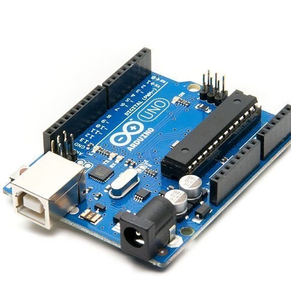
-Arduino UNO;
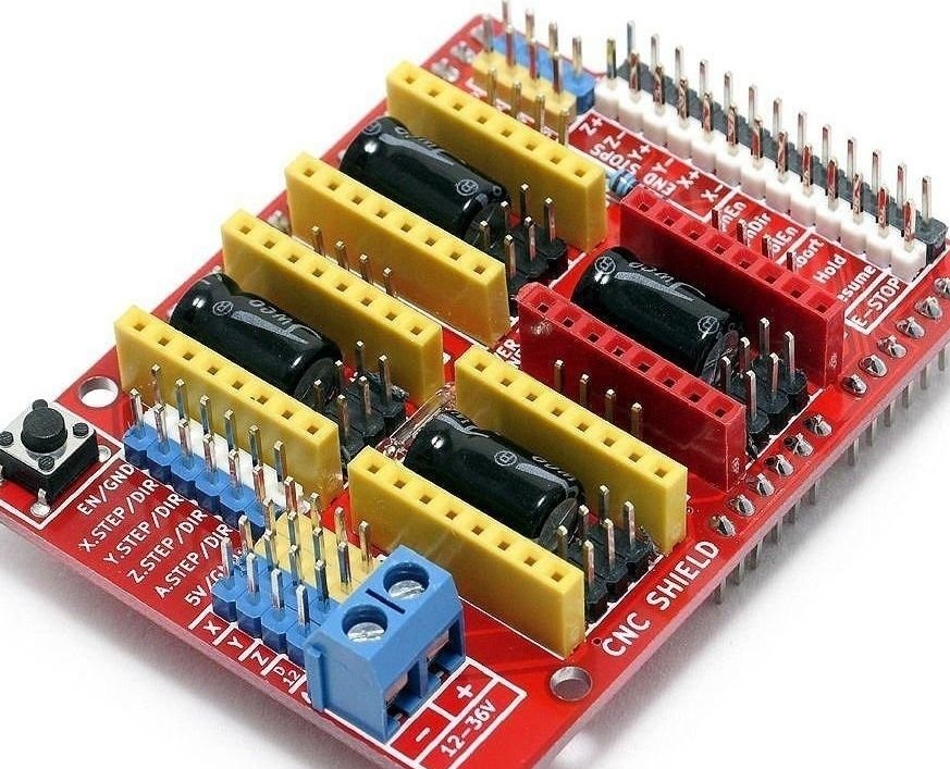
-Expansion board;
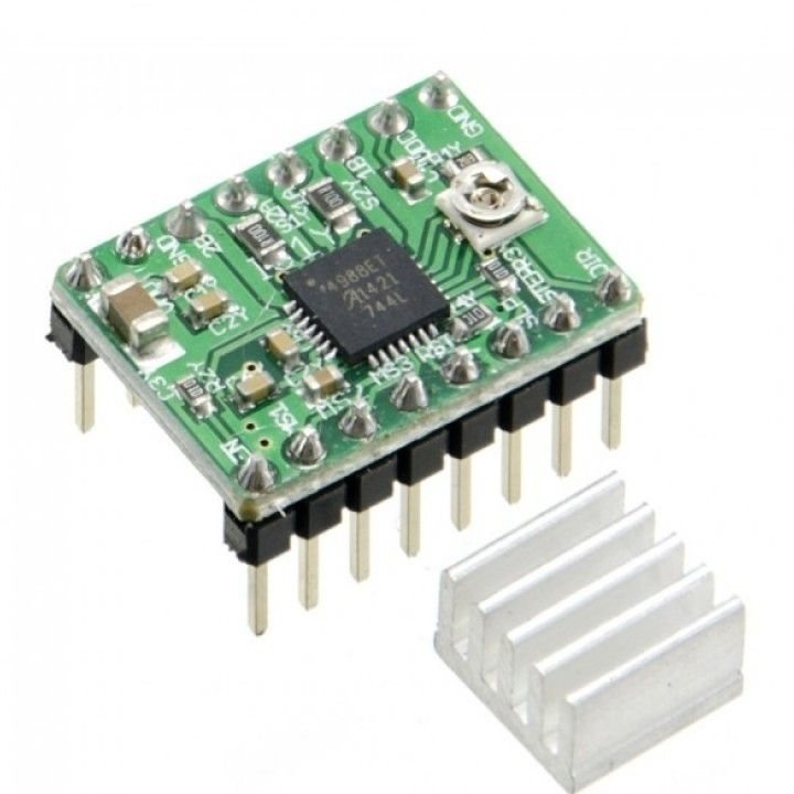
- A4988 stepper motor driver - 2 pcs;
-1000 mW laser module;
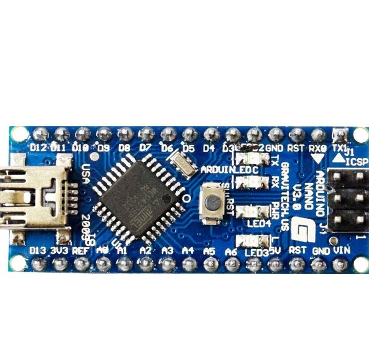
- Arduino Nano;
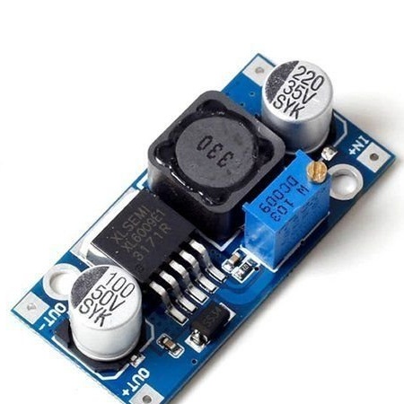
- XL6009 Boost Converter;
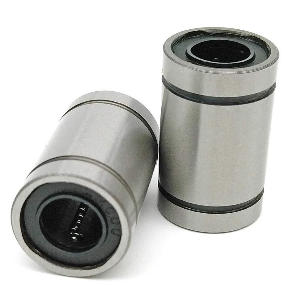
- LM8UU linear ball bearings - 6 pcs;
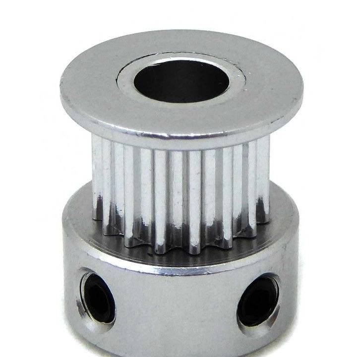
Pulley - 4 pcs;
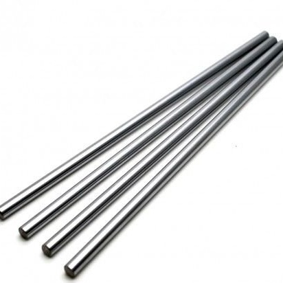
- Rods diameter 8 mm, length 300 mm -4 pcs;
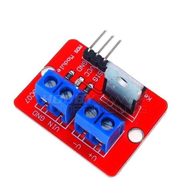
-module IRF520 Mosfet;
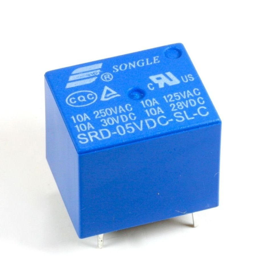
- Relay;
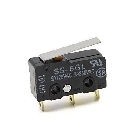
- Limit switches - 2 pcs;
-Step engines 2 pcs;
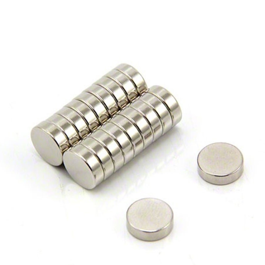
- Neodymium magnets 18 x 5 mm x 3 mm;
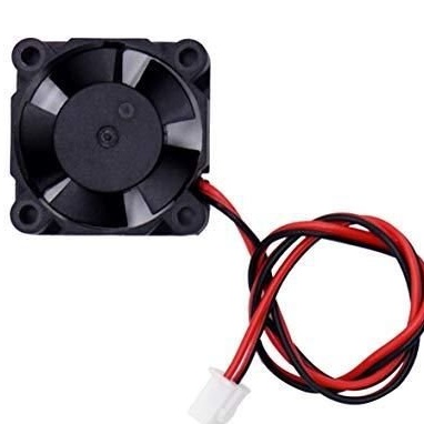
-30 * 30 mm 5 volt cooling fan;
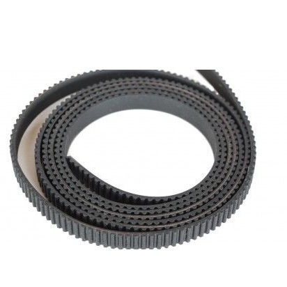
-Belt;
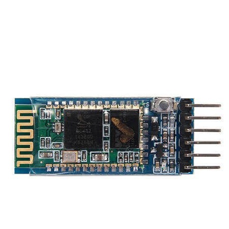
-HC-05 Bluetooth module;
-SG90 servomotor;
Screw terminals
-Heat-shrink tubing;
-Super glue;
-Cable ties;
-Fasteners
M3 30mm
M3 12mm bolts
M4 40mm
M3 nuts
M4 nuts;
- Plywood 8mm 48 x 42 cm;
-5mm transparent acrylic sheet 22 x 22 cm;
- MicroUSB cable;
-Sandpaper;
-Nadfil;
-Screwdriver;
-Soldering accessories;
-Pliers;
-Scissors;
-Nippers;
-Computer with software;
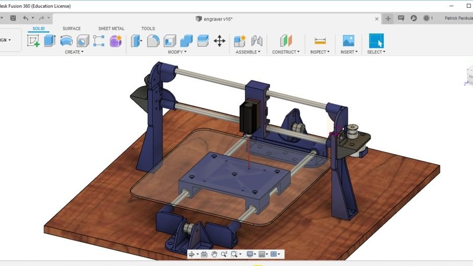
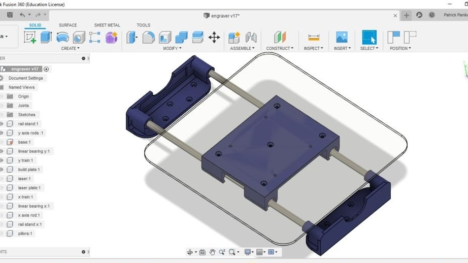
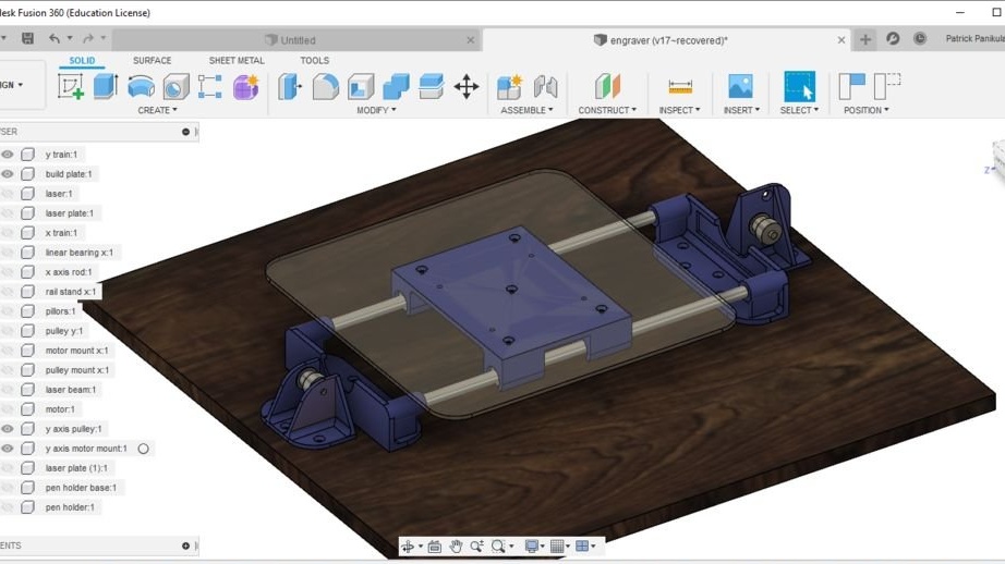
Step One: Design
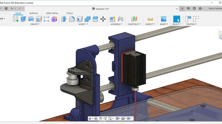
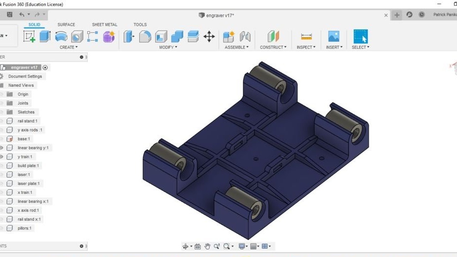
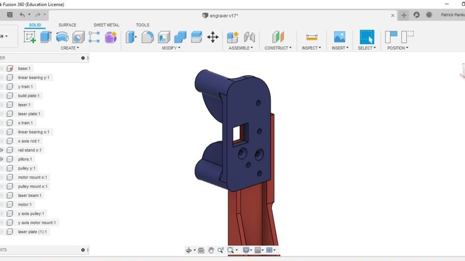
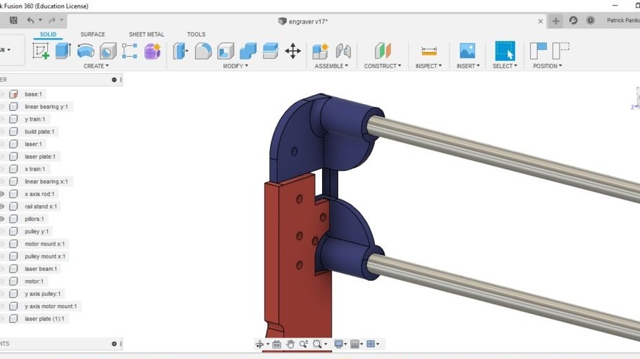
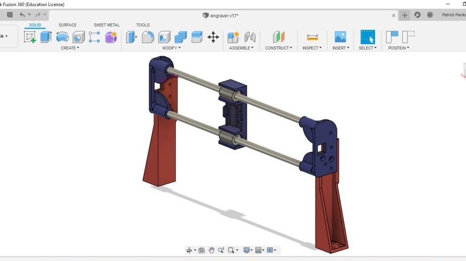
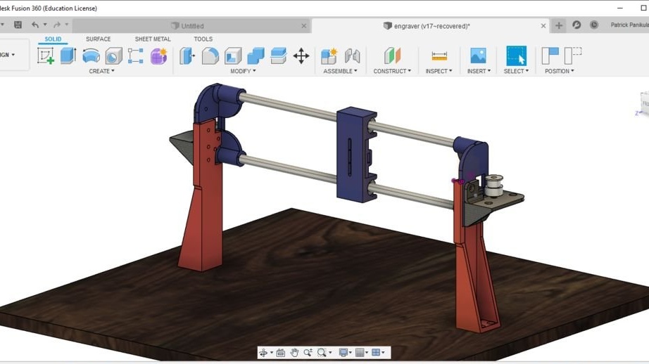
The wizard began by designing the base and holders of the Y-axis shaft. Because the holders consist of two identical components, the mirror function in the Fusion 360 made work easier. The mirror function was used several times in the development of this laser engraver.Unlike other CAD software, one of the great features of Fusion 360 is that it allows you to create multiple components on one screen with a link to other components, i.e. model can be designed assembled.
The height of the X axis guides depends on the focal length of the laser used. You just need to make sure that the laser height is in this range. Final focusing of the laser beam can be done by adjusting the lens on the laser.
Fusion 360 also allows you to choose the appearance and material of the components to make the final design look real. The program allows you to convert and save developed components directly in the STL format for 3D printing.
Below you can download the Fusion 360 file with the engraver project.
laser engraver v16.f3d
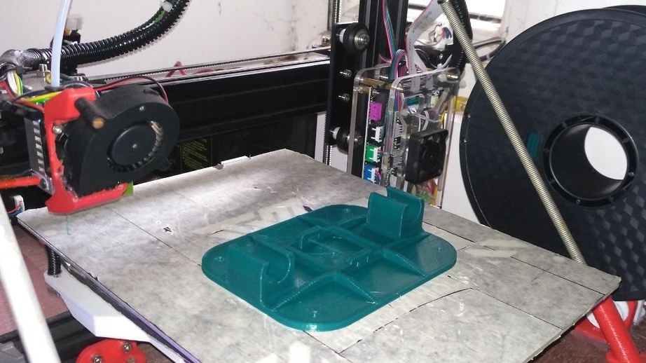
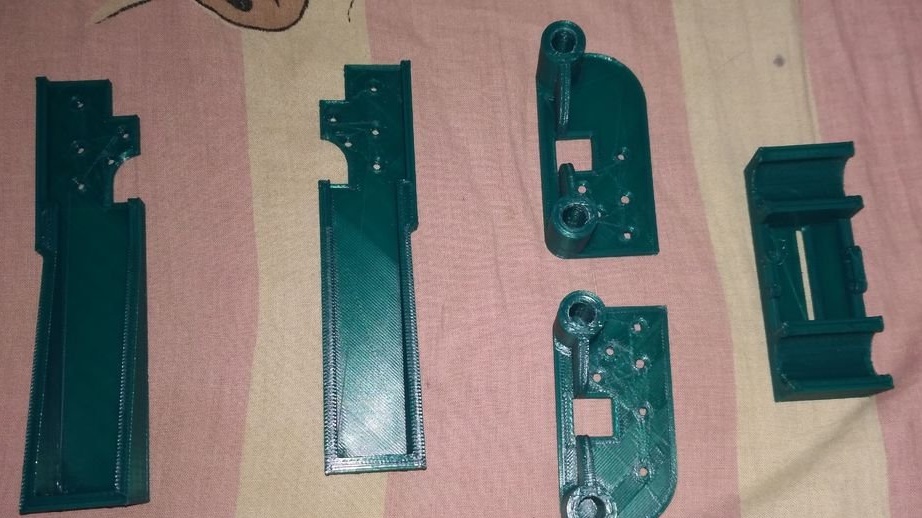
Step Two: 3D Printing
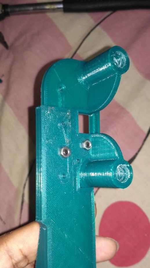
Then the wizard begins to print the details. All parts are designed in such a way that they can be easily printed in a 3D printer without supports.
The wizard prints details on a TEVO 3D printer.
Material: PLA (Dark Green)
Layer Height: 0.3mm
Filling: 30%
Wall thickness: 0.8mm
Top / Bottom Thickness: 0.9mm
Files for printing can be downloaded by clicking on this the link.
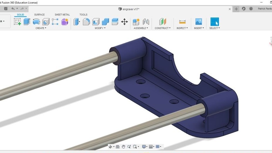
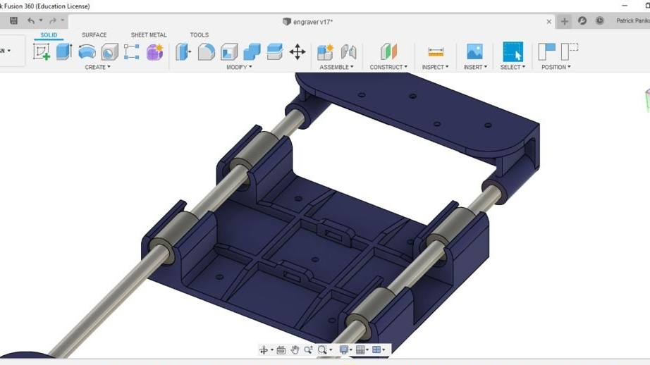
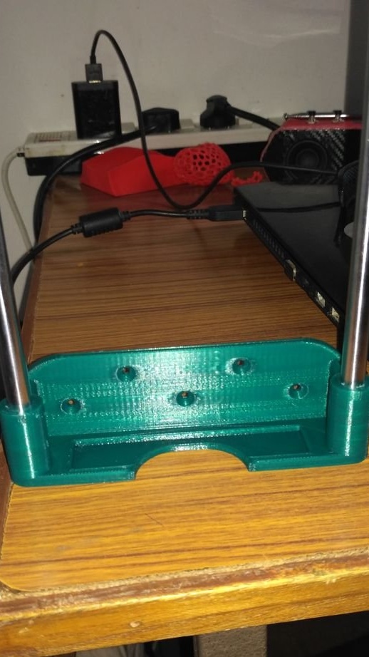
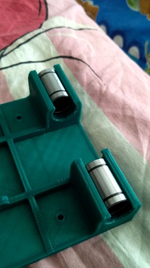
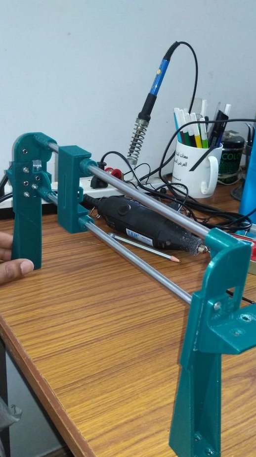
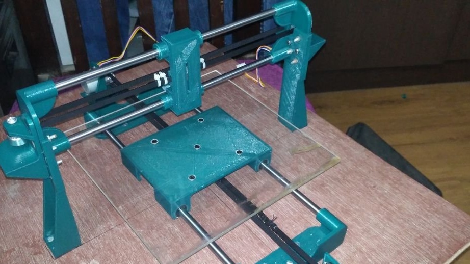
Step Three: Assembling the Y Axis
The wizard advises you to open the Fusion 360 PC build file before assembling. This helps make the build process more understandable.
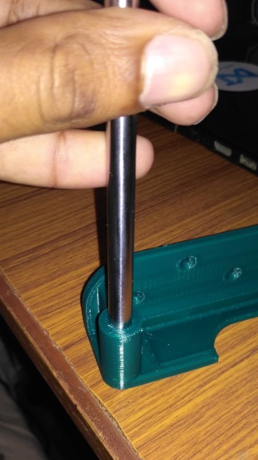
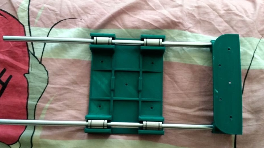
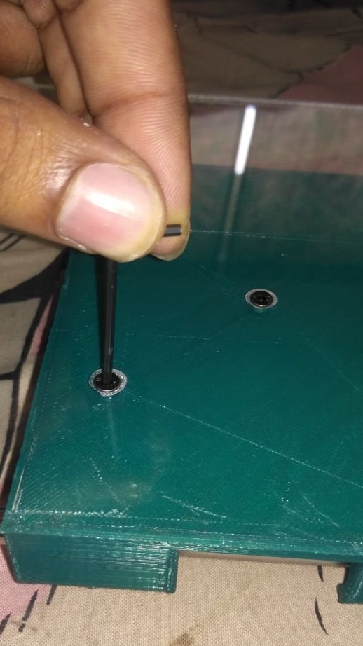
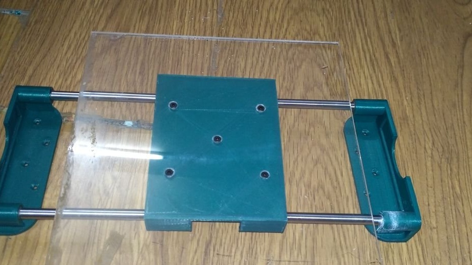
The wizard installs the rods and linear bearings. The master designed so as to avoid gluing parts, i.e. the fit is tight. The rods have to be filled into the seat with a hammer.
After assembly, make sure that the carriage moves freely.
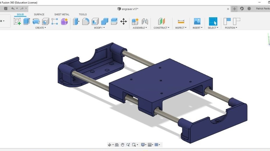
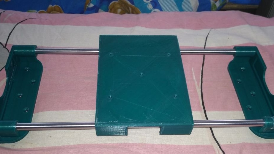
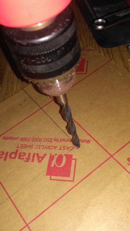
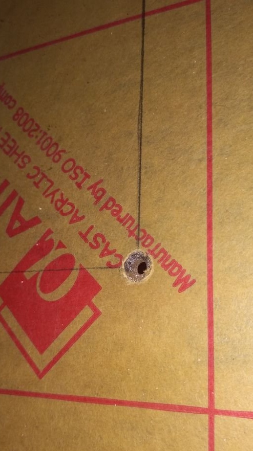
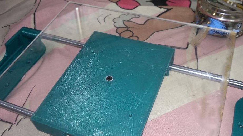
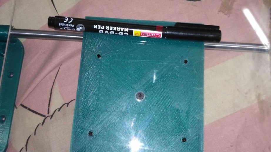
Step Four: Desktop
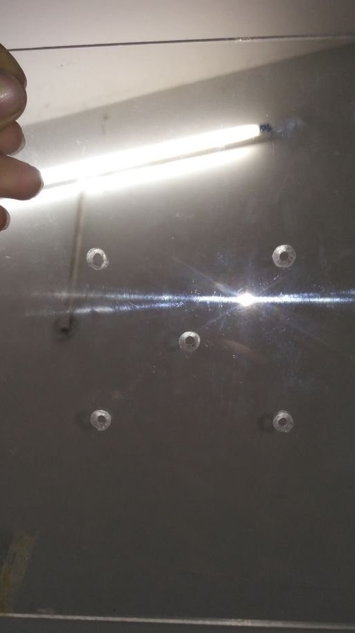
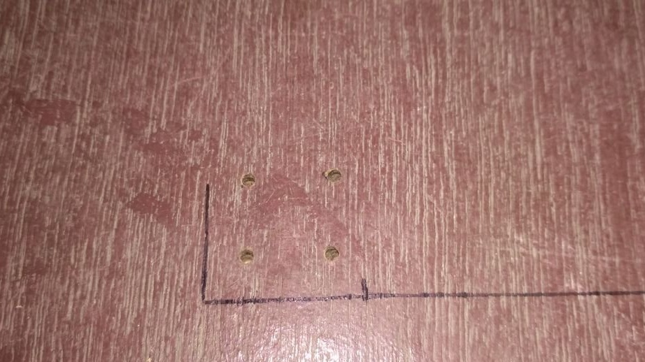
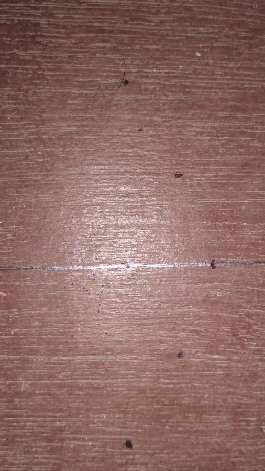
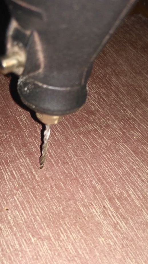
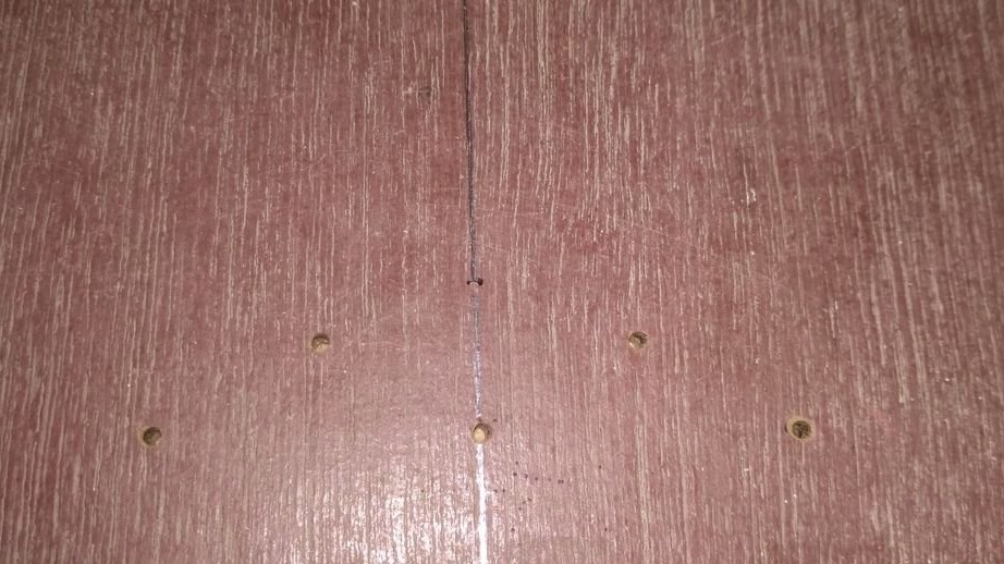
A hole is drilled on an acrylic sheet. Screws the sheet to the carriage and sets the edges of the sheet exactly parallel to the edges of the carriage. Marks and drills four mounting holes. Screws acrylic to the carriage.
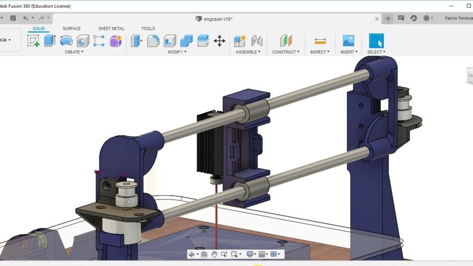
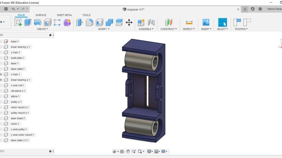
Step Five: X axis
Then the master collects the X axis. The guides for the axis were printed by the master, since the ones he bought turned out to be defective. According to him, after grinding and lubrication, these guides work no worse than purchased ones.

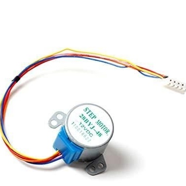
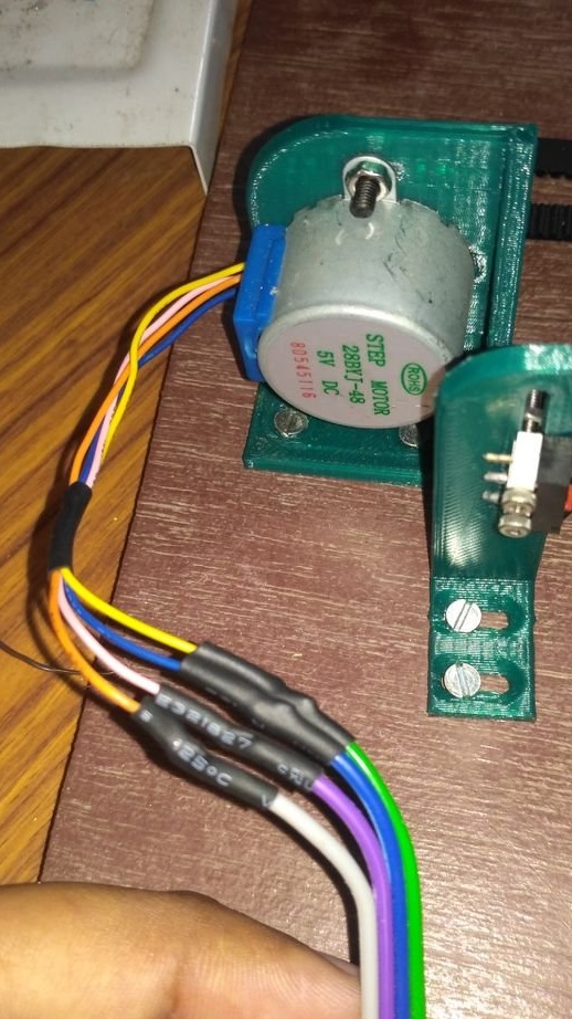
Step six: reworking the 28BYJ-48 unipolar engine into a bipolar
There are two main reasons why you need to convert a unipolar motor into a bipolar motor.
The bipolar motor control algorithm using the A4988 stepper motor driver is simpler than controlling a unipolar motor
The expansion board only supports bipolar stepper motors.
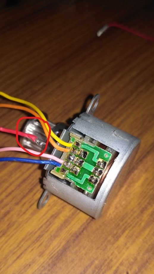
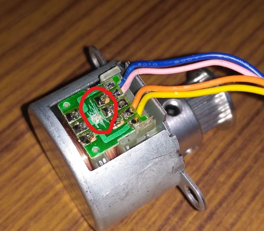
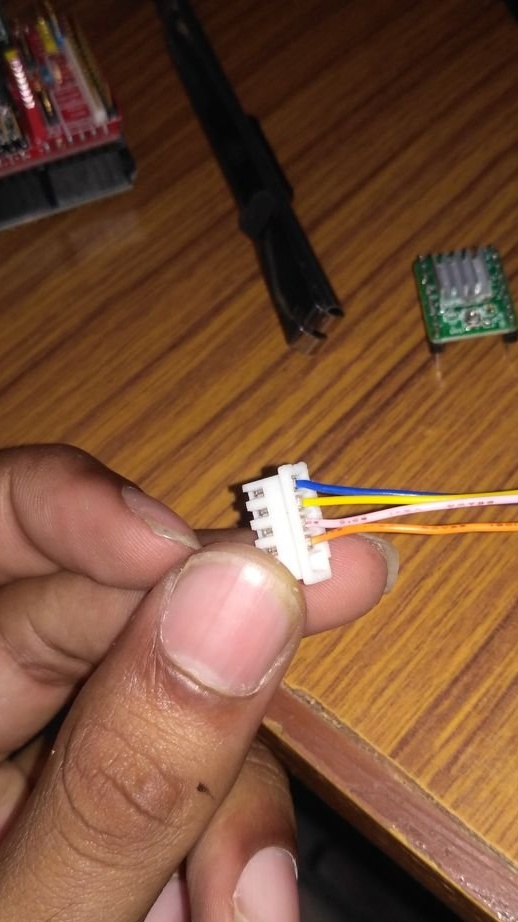
You can remake the engine in three steps.
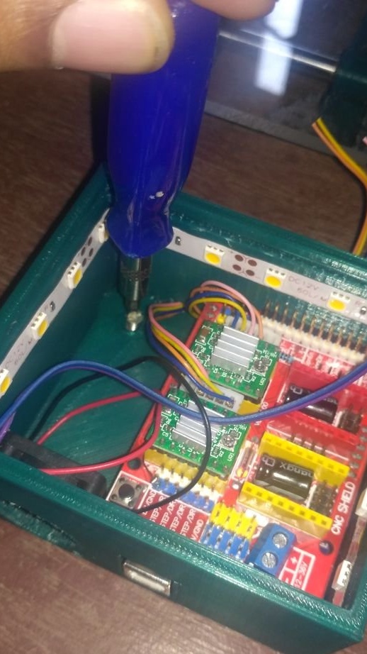
Open the blue plastic case, disconnect the red wire from the board, as shown in the first photo.
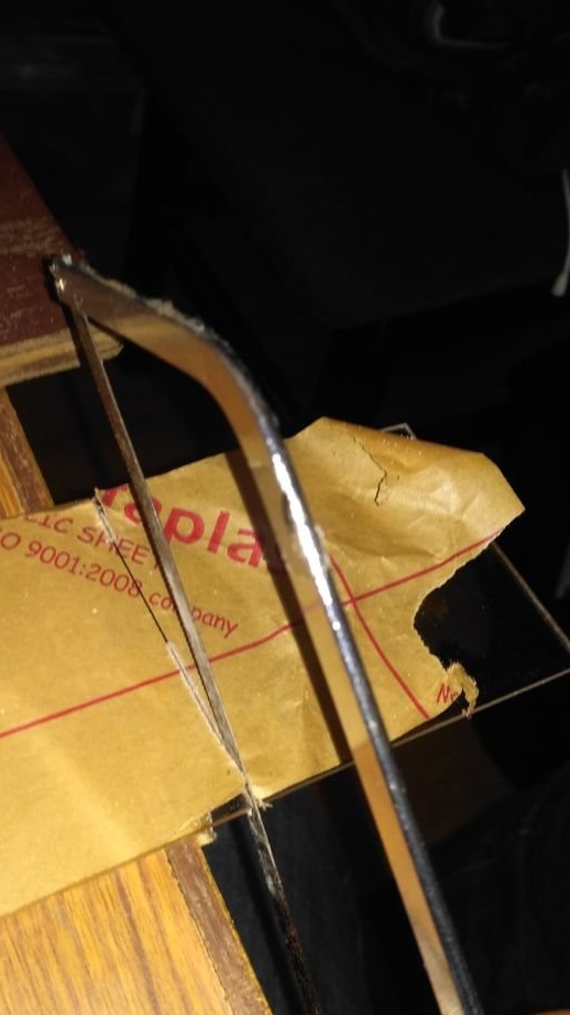
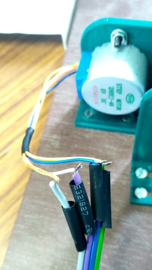
Now you need to damage the track, as in the second photo and change the wires in the block, as in the third photo.
Seventh step: installing the motor, pulley, belt
Installs the engine. On the shaft, the engine secures a pulley. The second pulley sets on the opposite side of the engine. Fastens the end of the belt with ties. Passes the second end of the belt through the pulleys and also fastens.
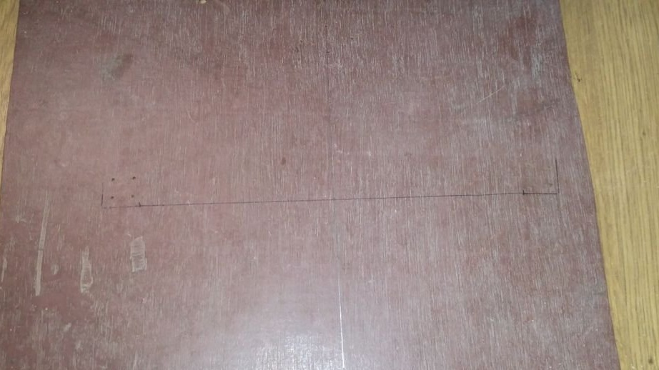
Step Eight: Foundation
The base is made of plywood. To him, the master attach the X axis.
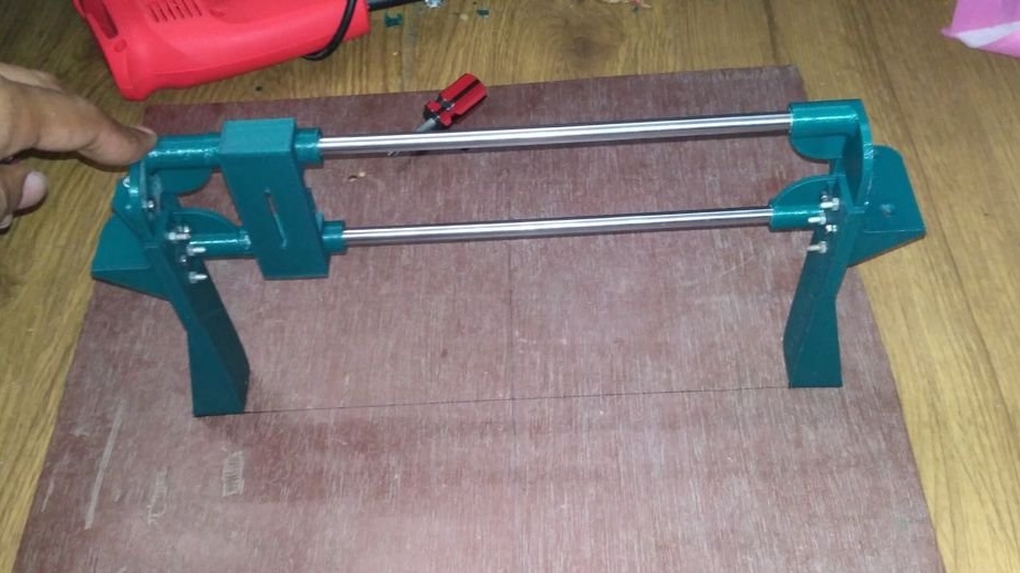
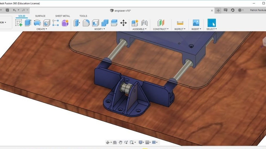
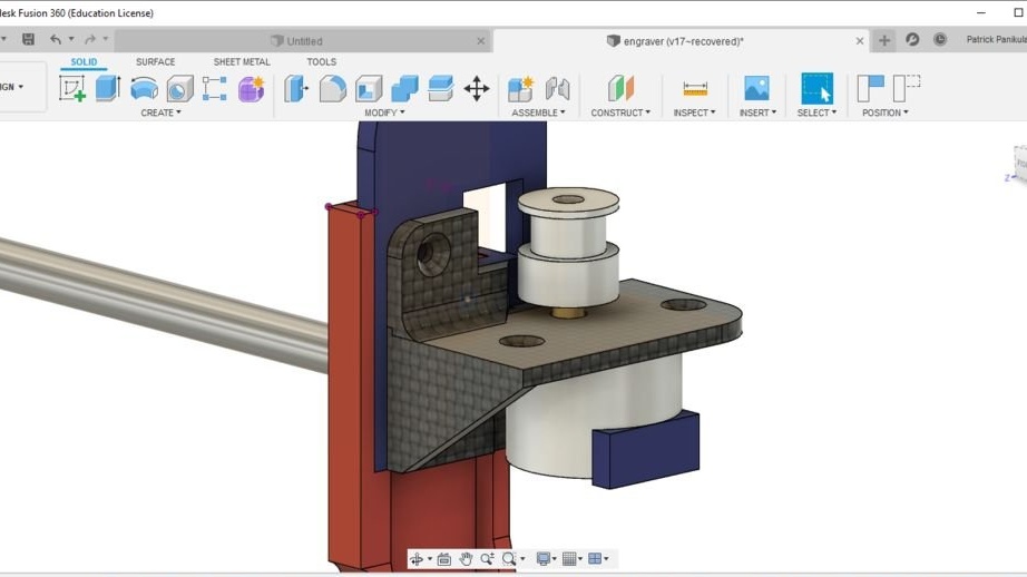
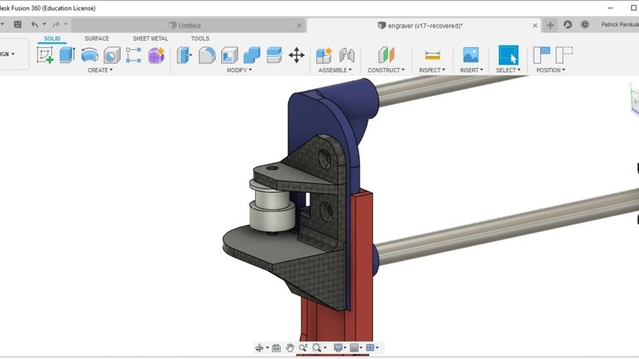
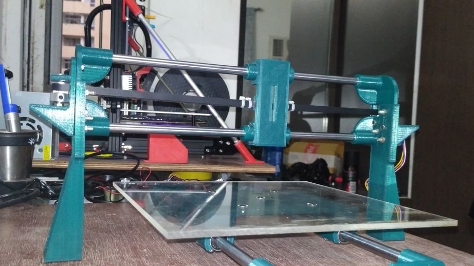
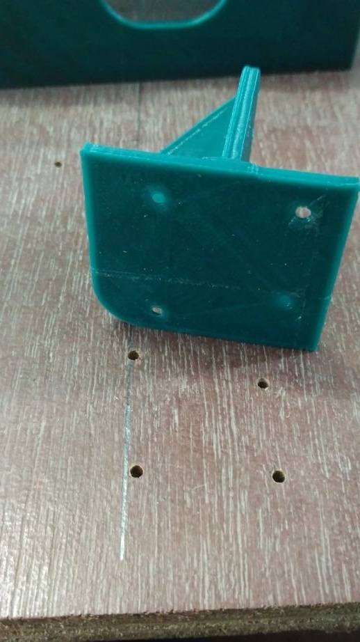
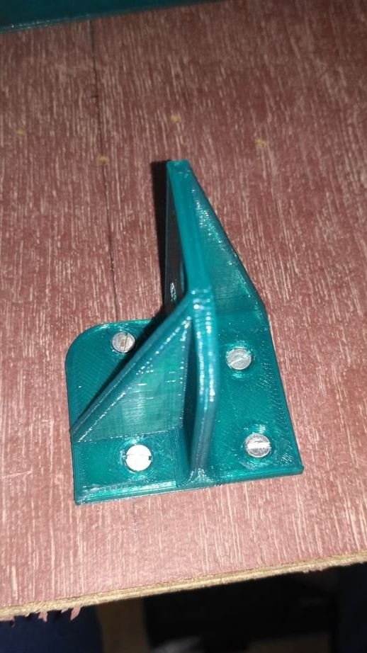
Step Nine: Y axis
Collects the Y axis. This is a difficult step.
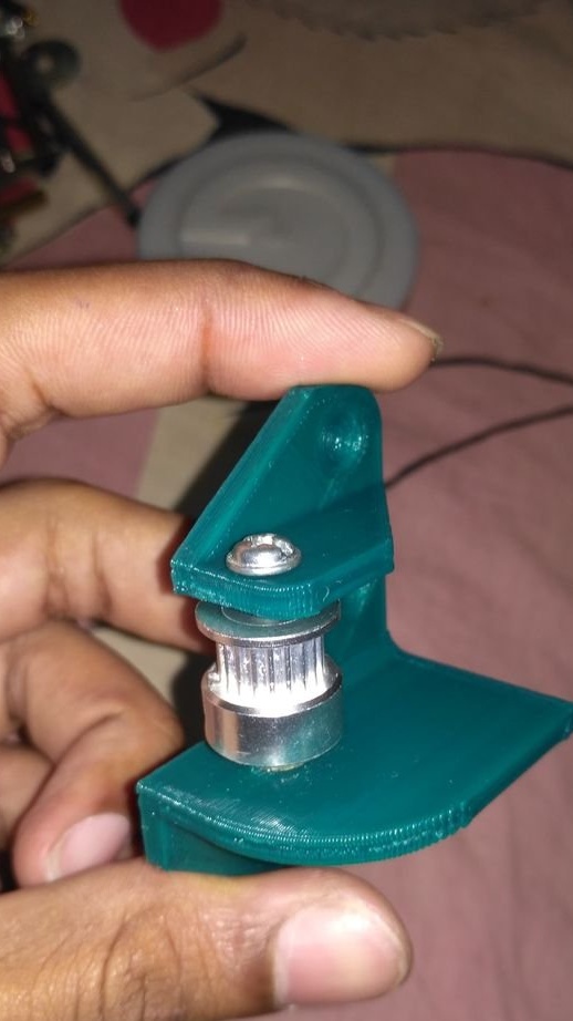
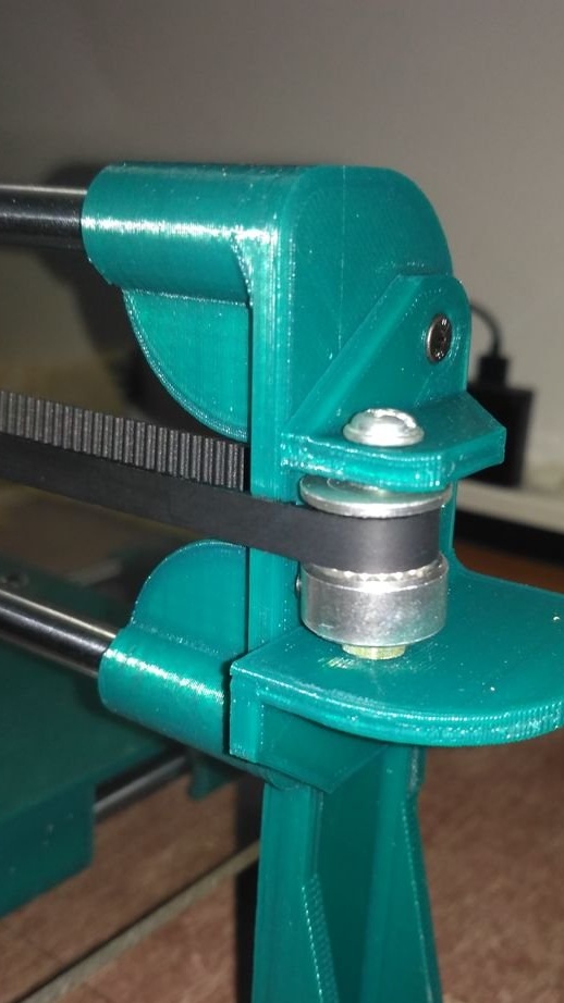
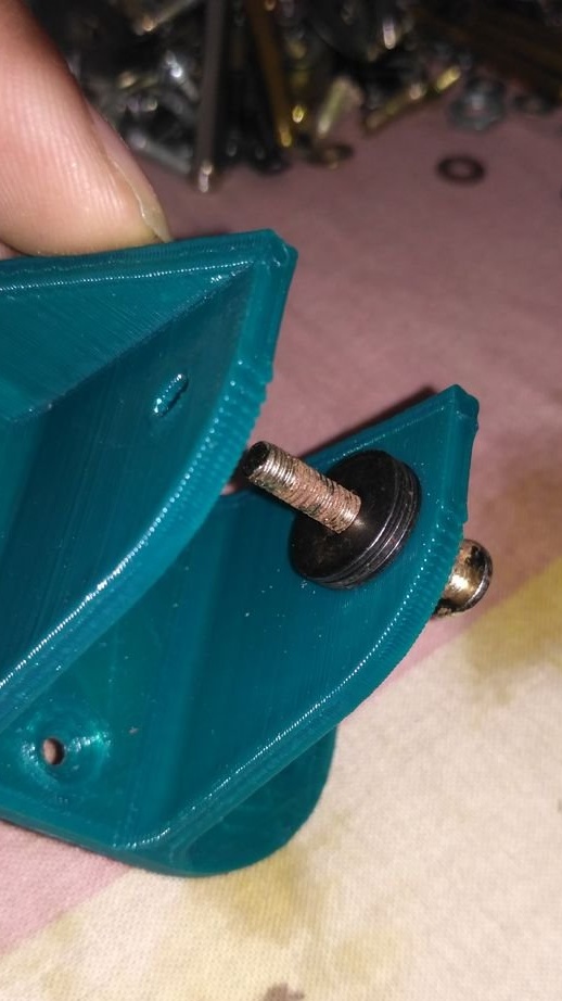
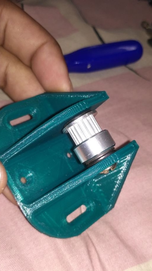
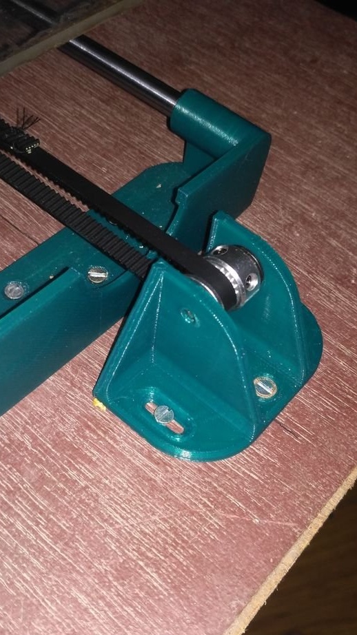
Assemble the pulley holder using the Y axis pulley holder, pulley, 40 mm M4 bolt / nut and metal washers as shown in the first two photos.
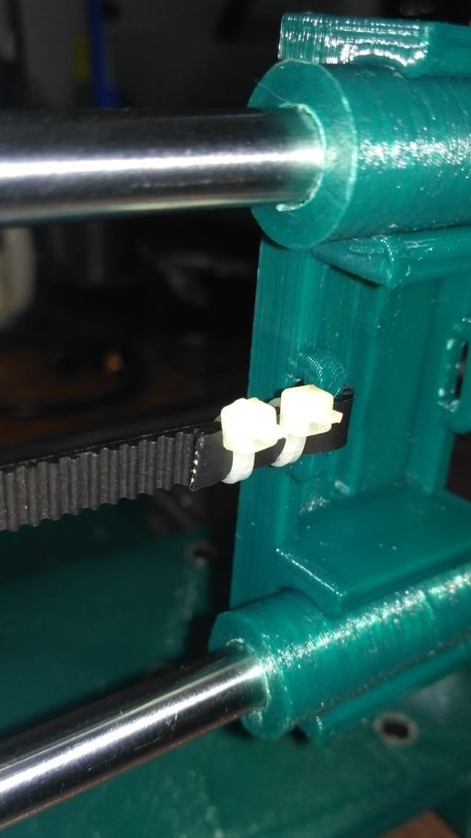
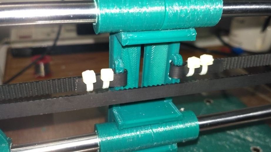
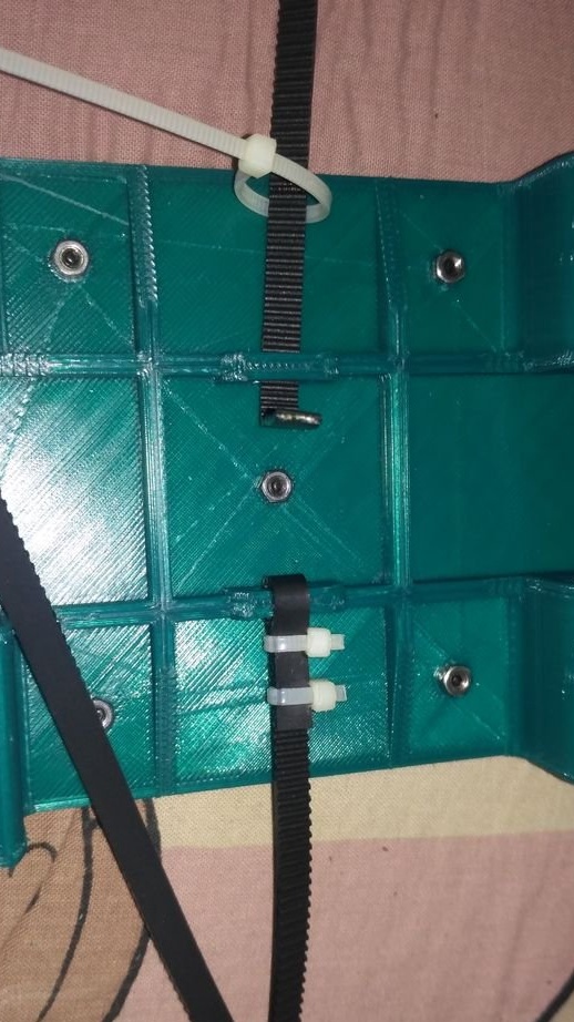
Now tie one end of the timing belt to one of the slots under the Y-axis carriage.
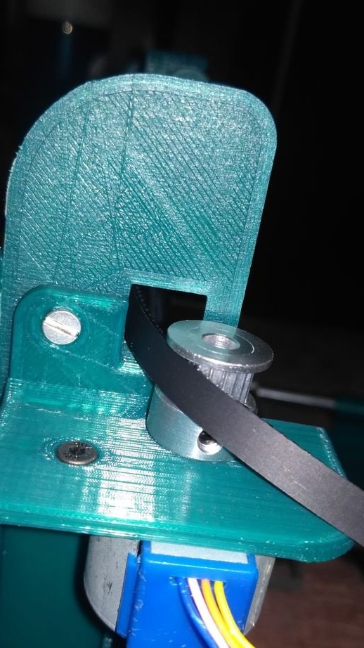
Pass the free end of the belt through the pulley assembly you made earlier, and then snap it into the second groove located under the Y-axis carriage.
After these 3 steps are completed, you need to screw the Y-axis assembly to the plywood base.
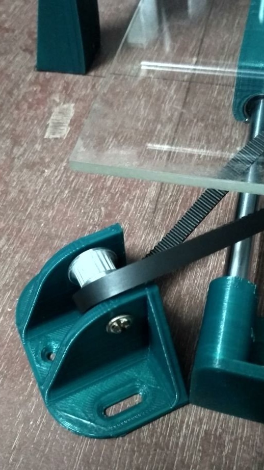
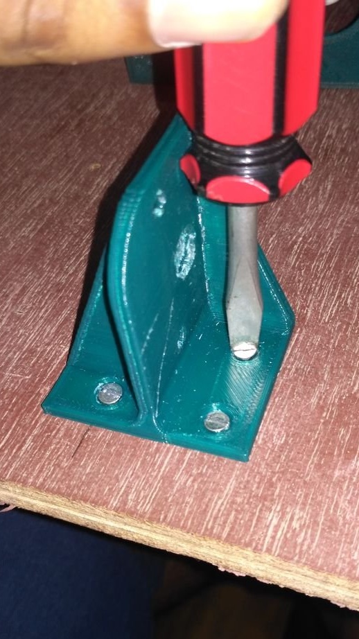
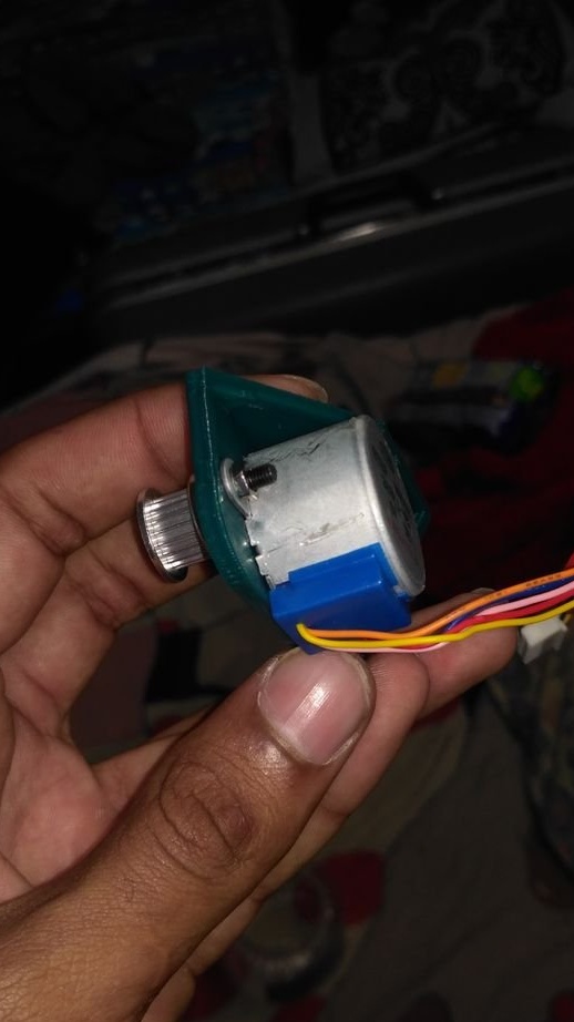
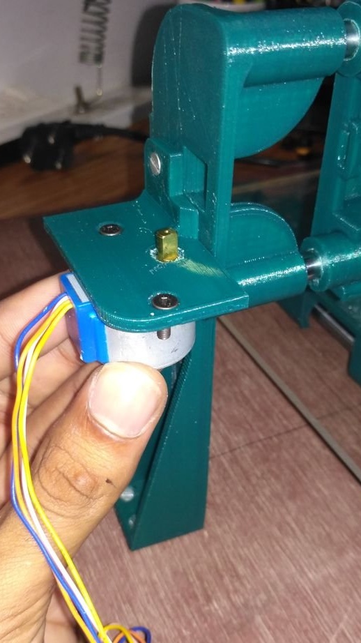
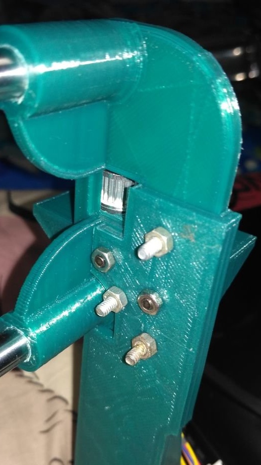
Attach the stepper motor to the Y-axis motor mount using two 12 mm M3 bolts and nuts.
Now screw the Y-axis pulley holder and engine mount to the plywood base.Do this after adjusting both sides to get the correct belt tension. A belt tensioner will be added later.
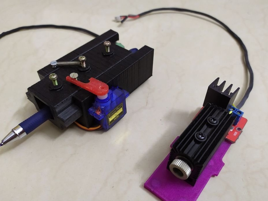
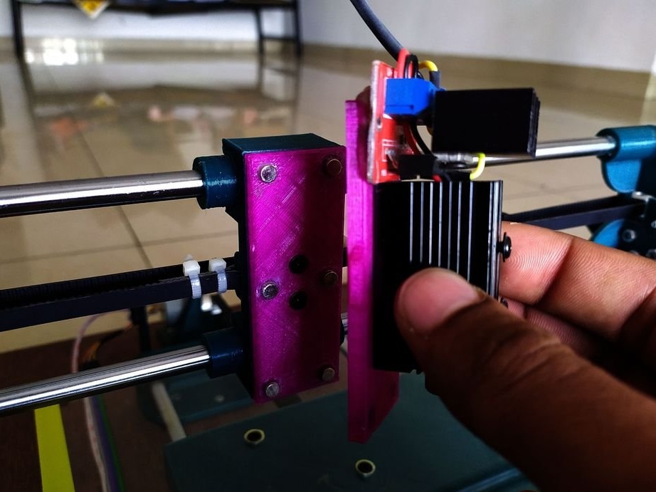
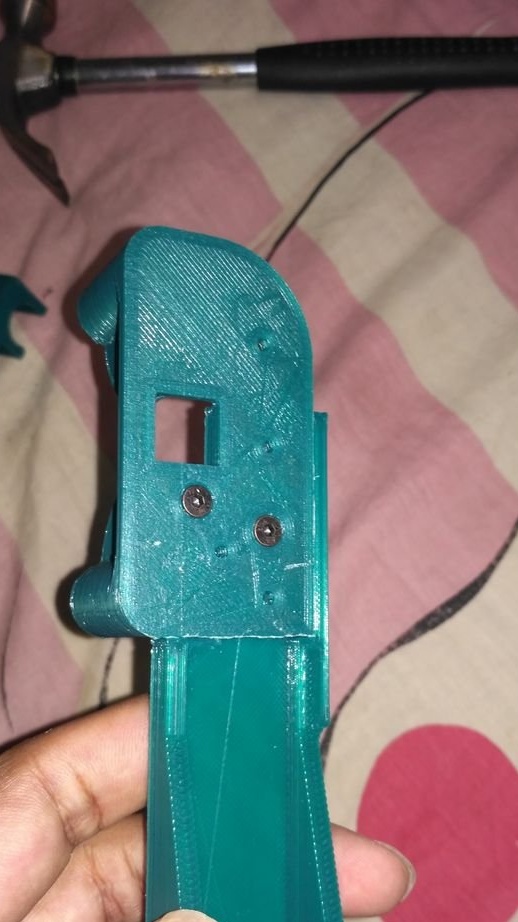
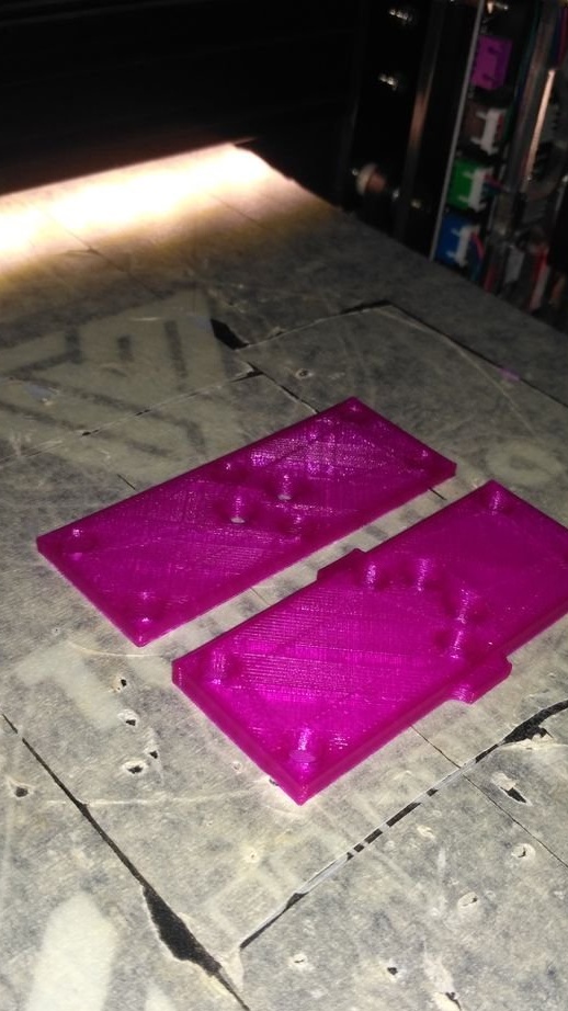
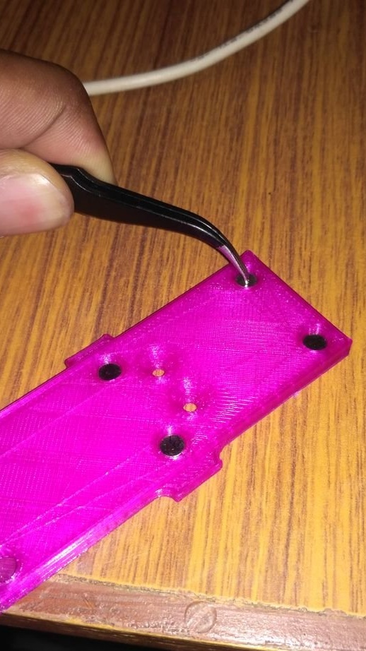
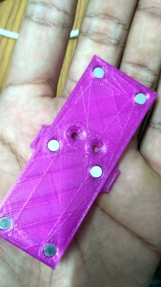
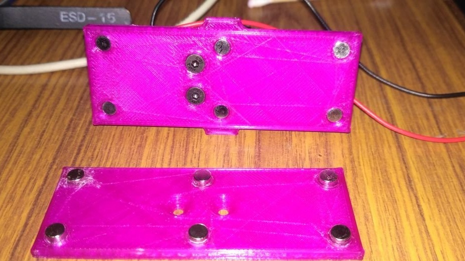
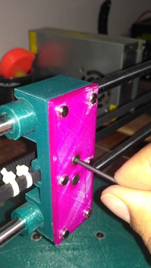
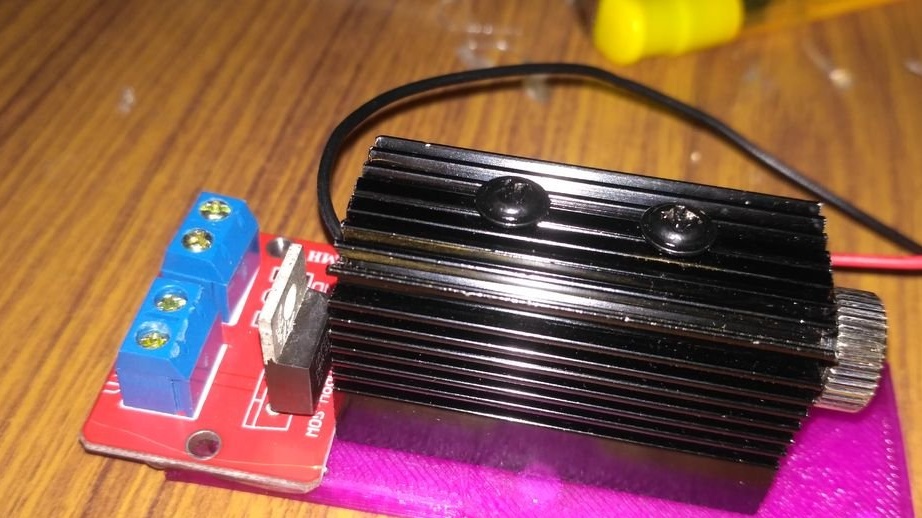
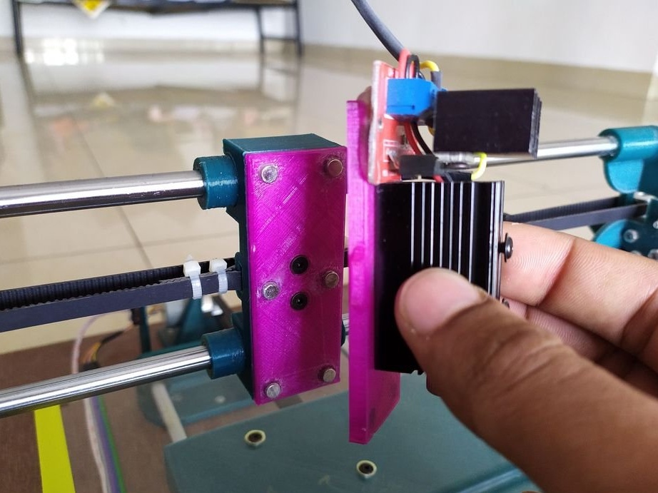
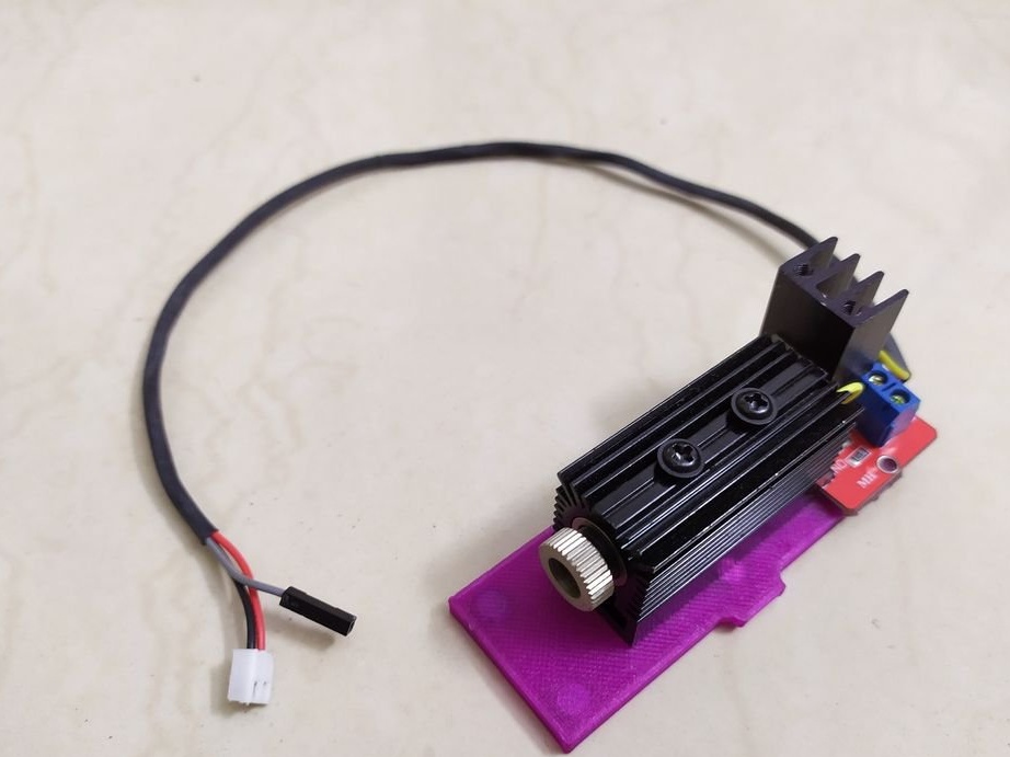
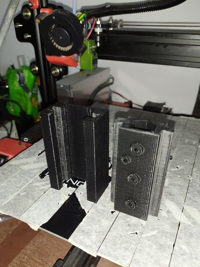
Step Ten: Laser Module
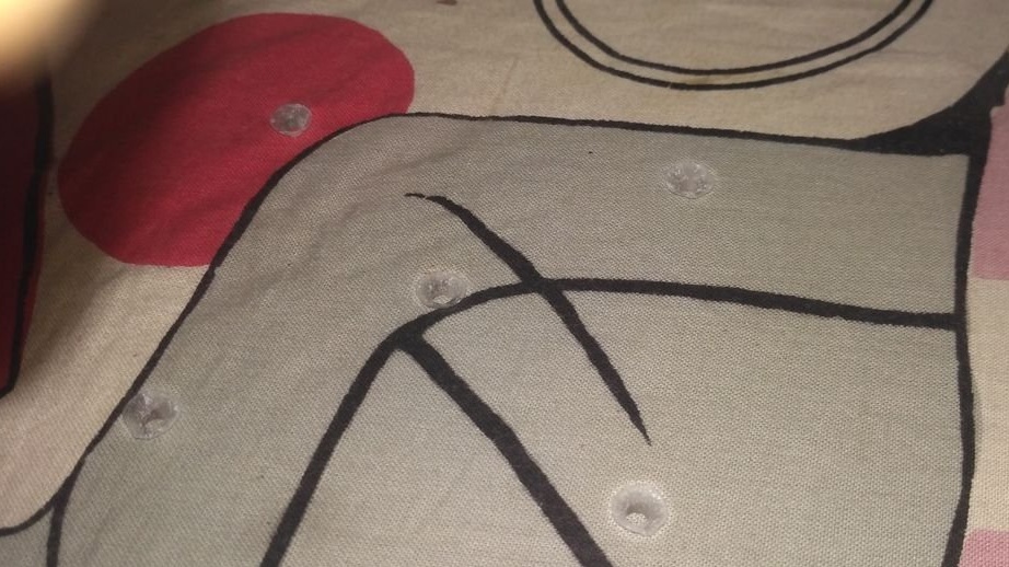
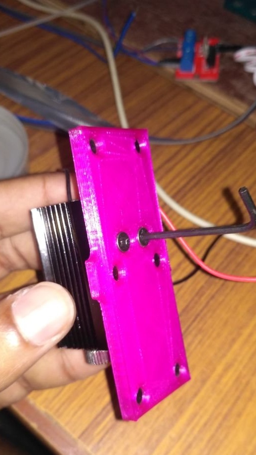
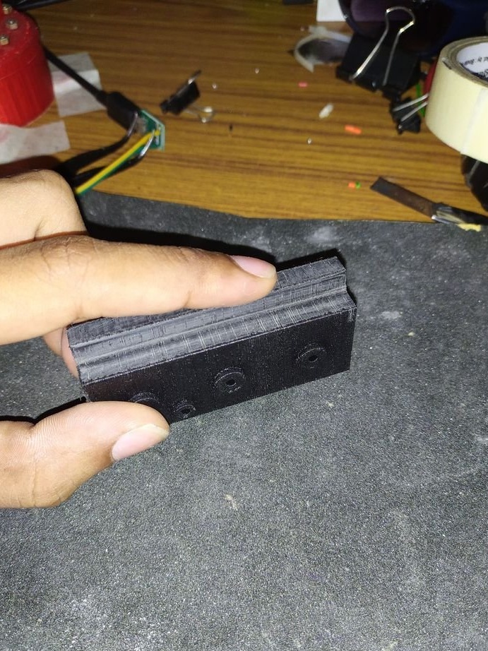
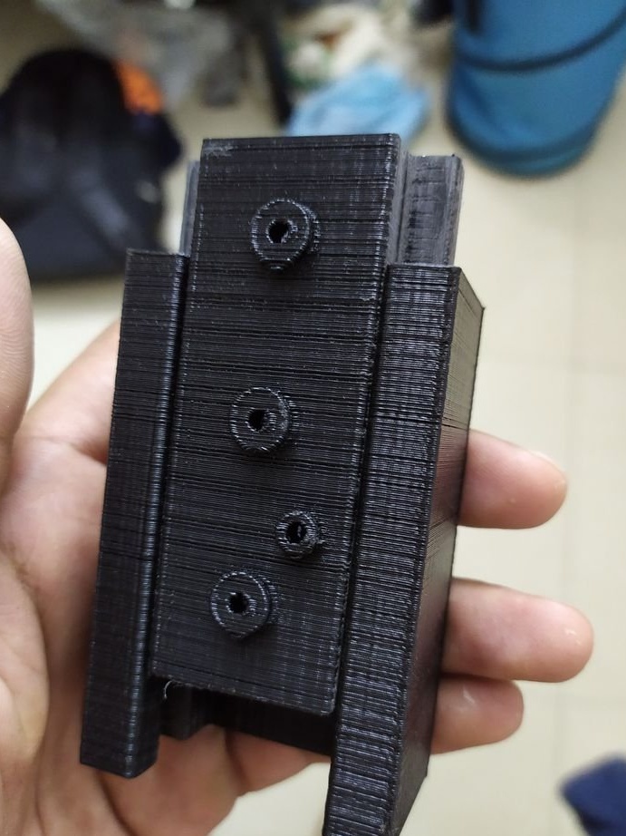
As indicated, in the specifications, the machine implemented a quick replacement of the laser module with other executive modules. For this, the master made two rectangular parts (covers). Six neodymium magnets are installed in each. One cover is attached to the X axis, the laser module is attached to the other.
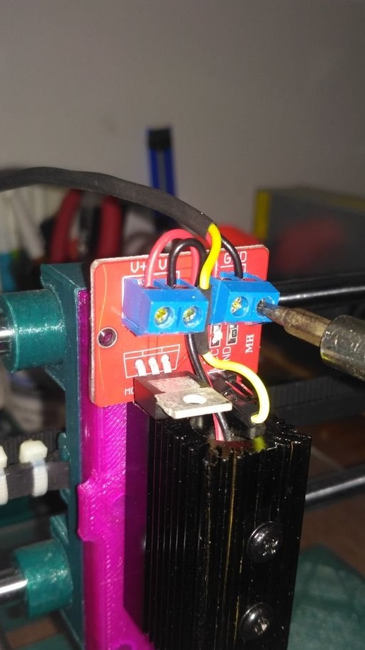
The wires are mounted as follows.
+ and - lasers are connected to V + and V-, respectively, of the MOSFET module. Power is connected to VCC and GND respectively. The signal wire is connected to the signal pin of the MOSFET module.


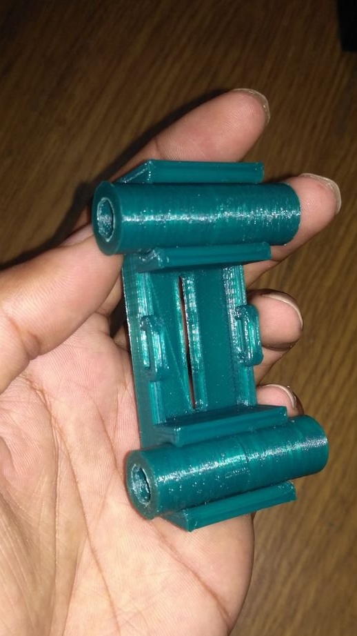
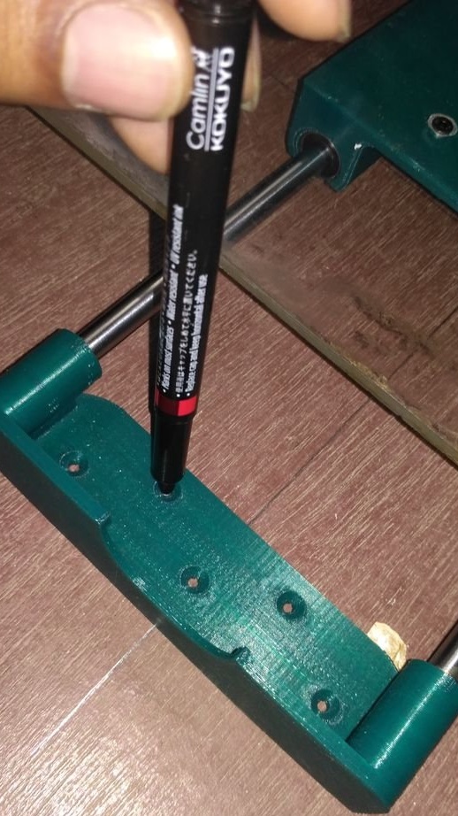
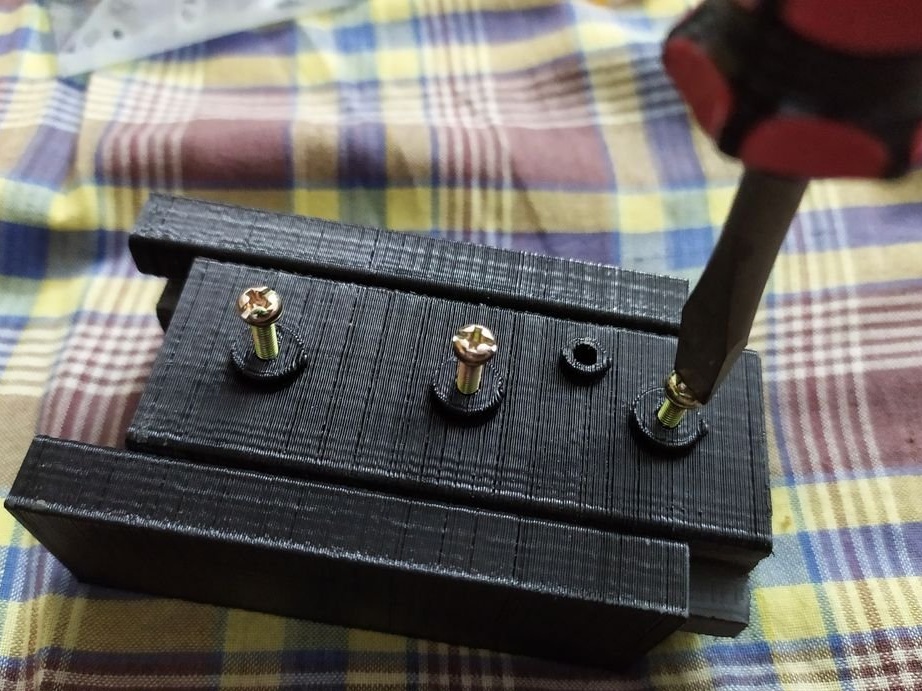
Step eleven: plotter
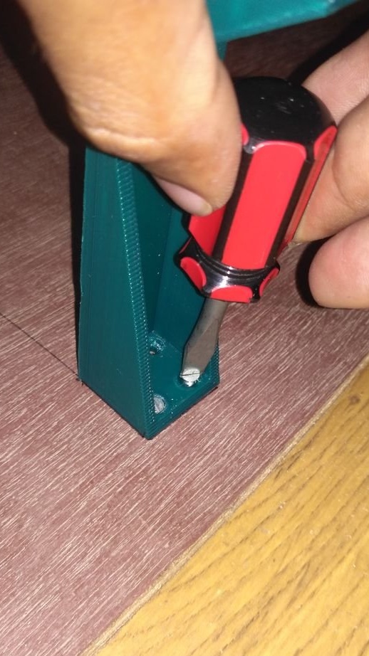
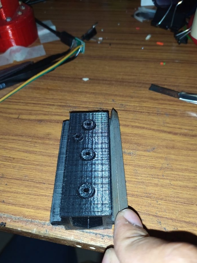
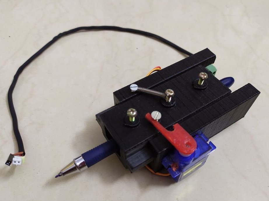
Collects a plotter. As soon as both parts are printed, the master polishes the planes that are in contact with each other, smooths them with a file and sandpaper, until both parts slip together with very little friction.
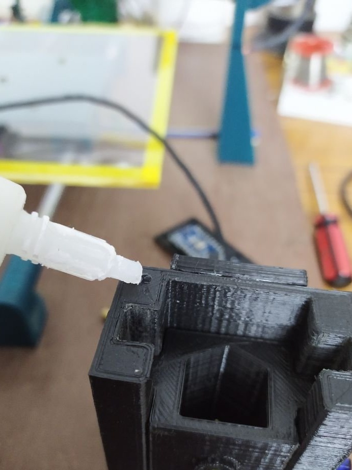
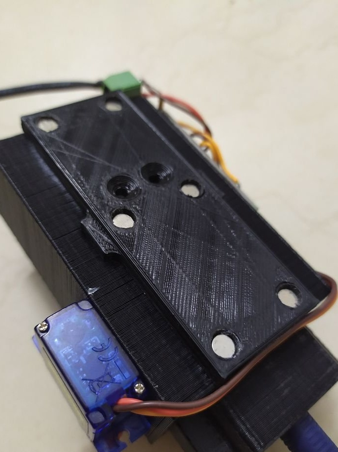
Now tightens the 40 mm M3 screws and sets the spring.
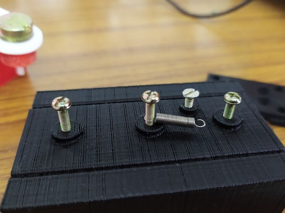
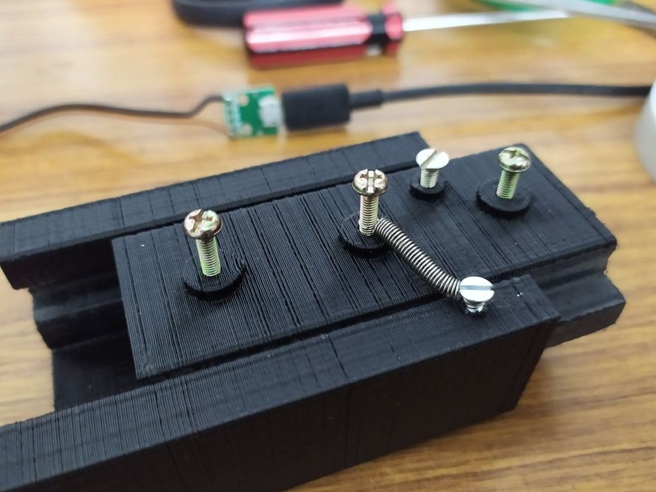
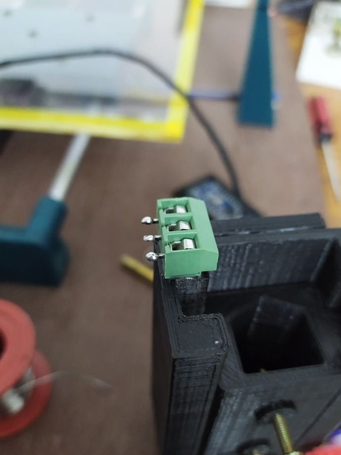
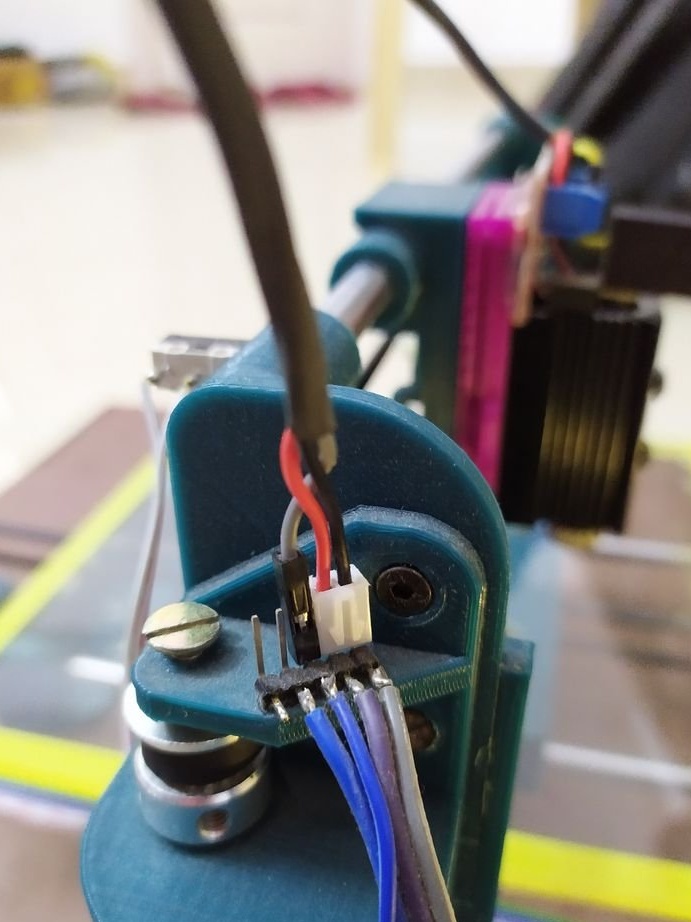
The servo motor, terminals and Arduino sticks as shown in the photo.
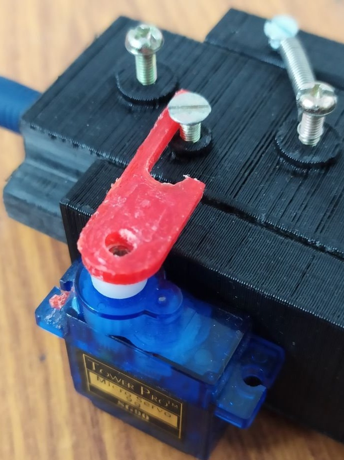
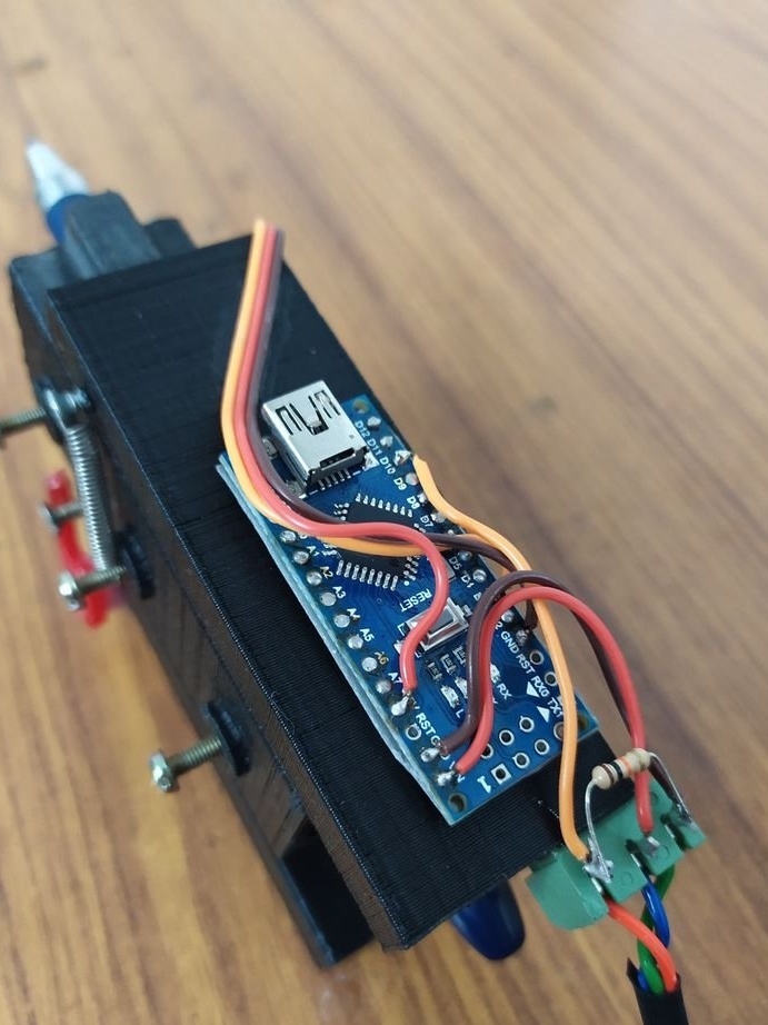
Here Arduino nano is used to convert laser control signals into PWM signals that can drive a micromotor.
It is connected as follows:
+5 Volt - Vin
-5 Volt - GND
Signal - D10
Servo power + ve - 5V
Servo power -ve - GND
Servo signal - D3
Then the code is loaded.
#include Servo myservo;
void setup ()
{
myservo.attach (3);
pinMode [10, INPUT];
}
void loop ()
{
if (digitalRead (10) == HIGH)
{
myservo.write (20);
}
else
{
myservo.write (60);
}
}
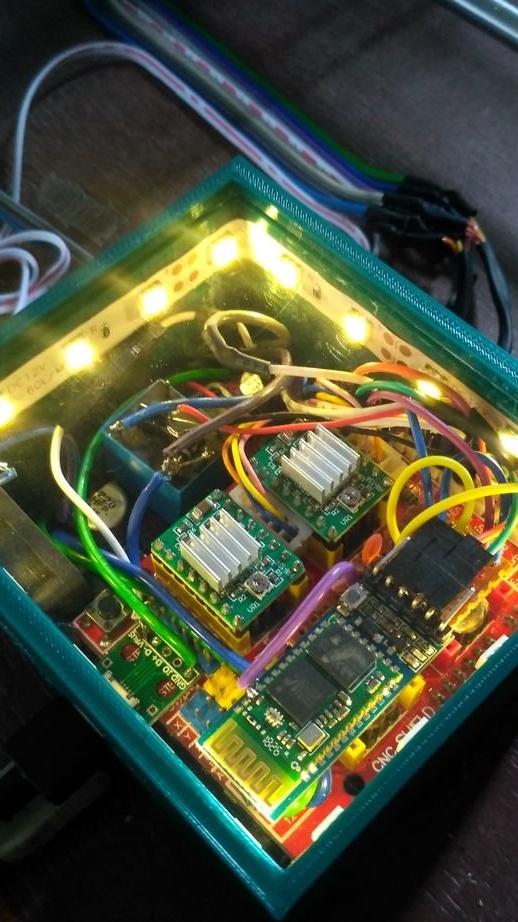
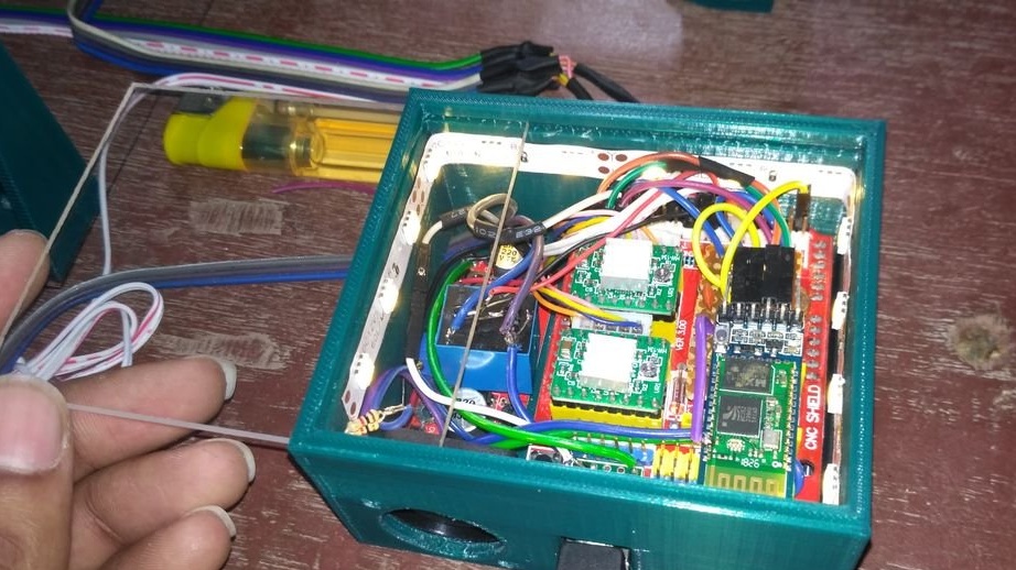
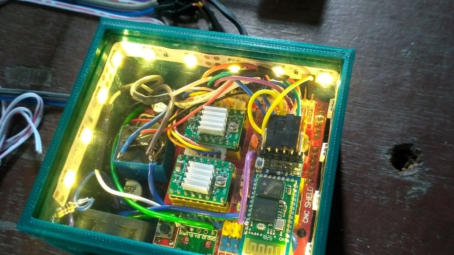
Step Twelve: Installation
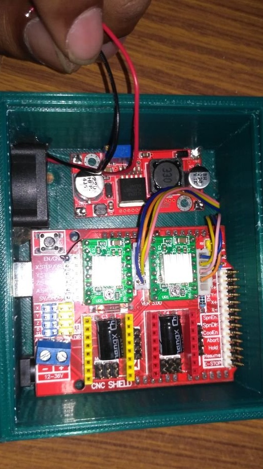
Installation according to the scheme.
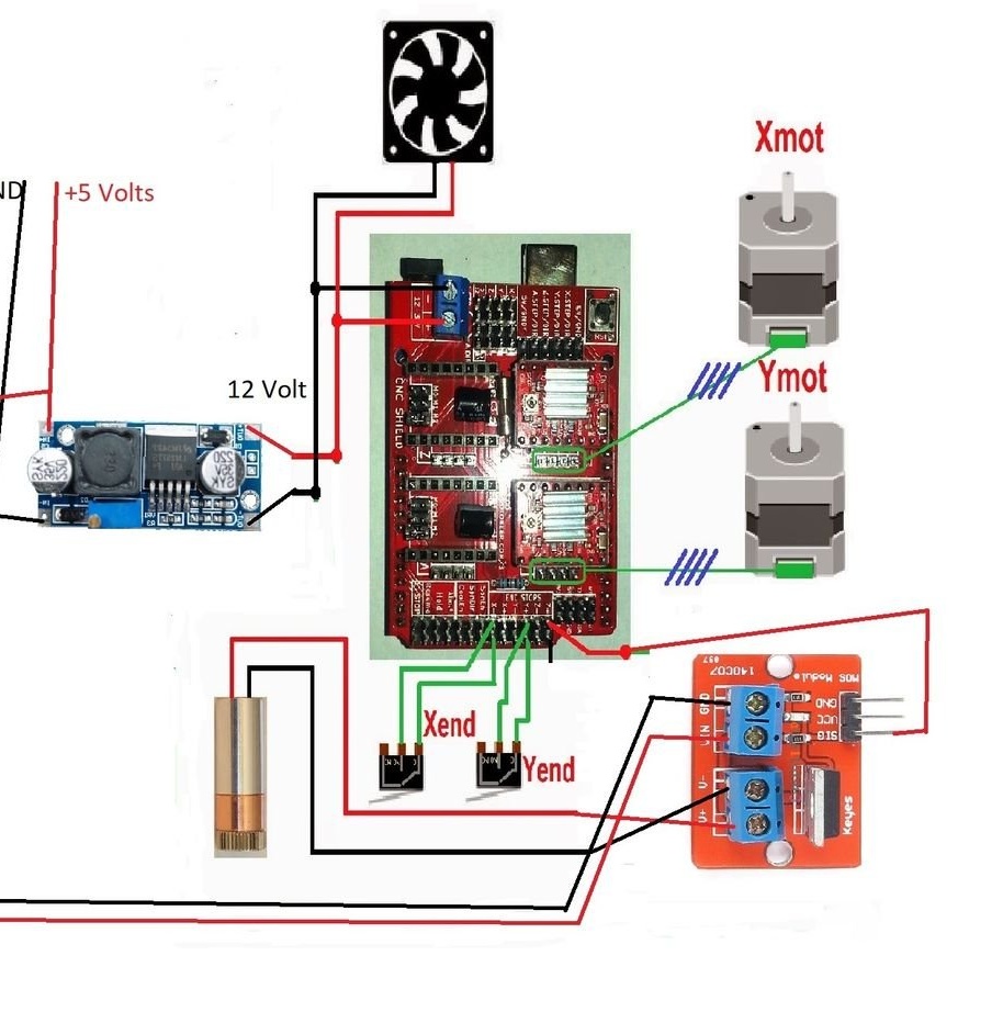
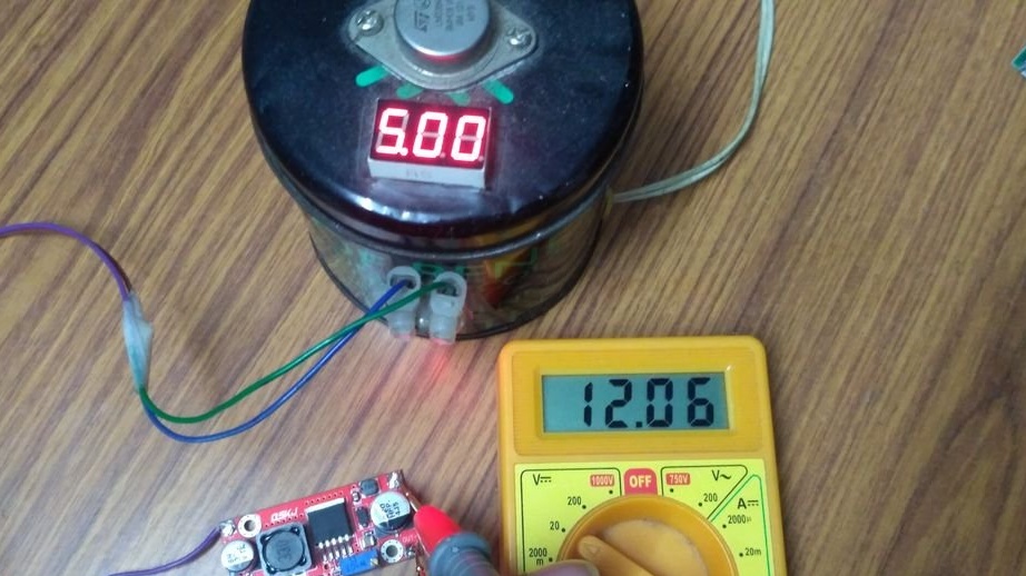
The boost converter is set to 12V.
Arduino is installed in the CNC expansion module.
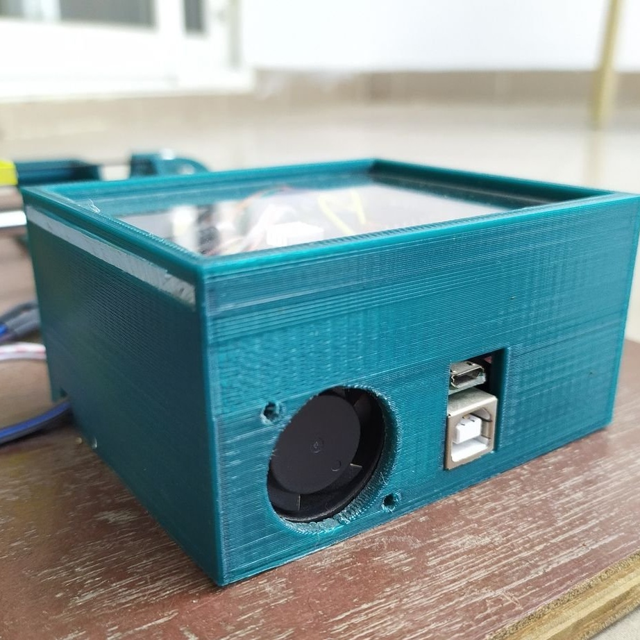
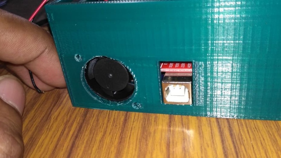
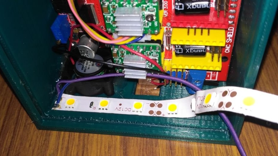
The fan is glued to the hole provided for this with hot melt adhesive.
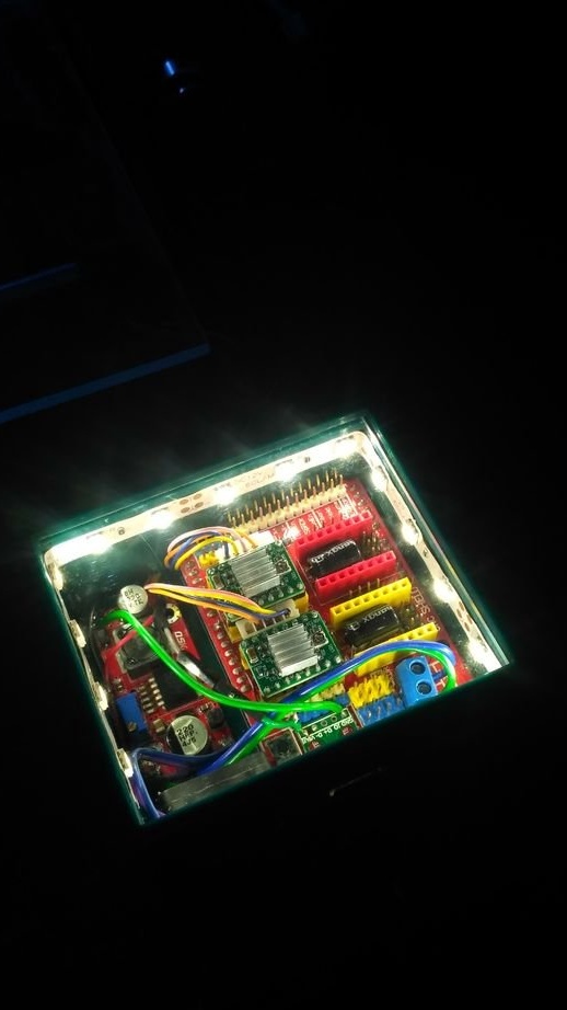
An LED strip has been added for both appearance and power indication.
The printed case is screwed to the plywood.
A transparent acrylic sheet 87 x 75 mm 2 mm thick is used as a body cover. It can be inserted through the groove provided for it on one side of the housing.
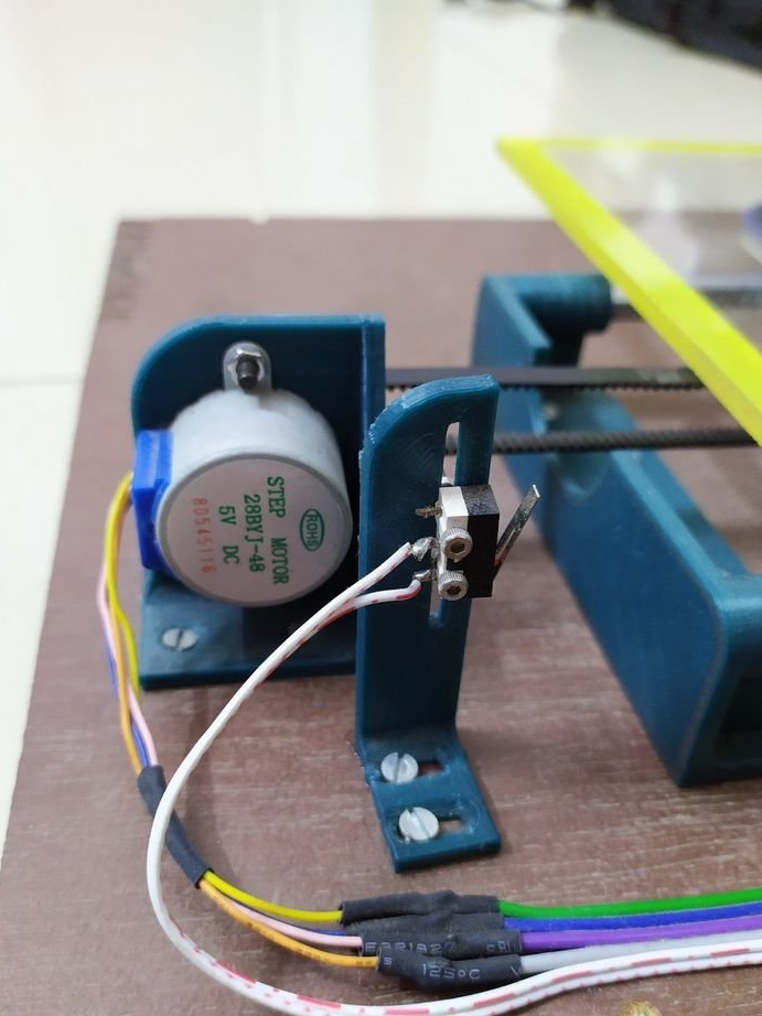
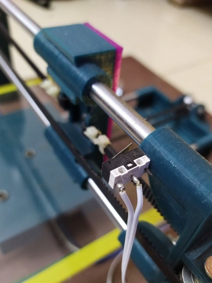
The limit switches are attached so that the button is pressed 3 mm before the bearings of each carriage collide with the traction holders.
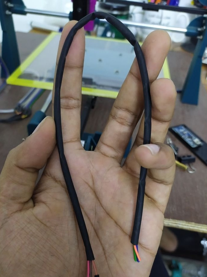
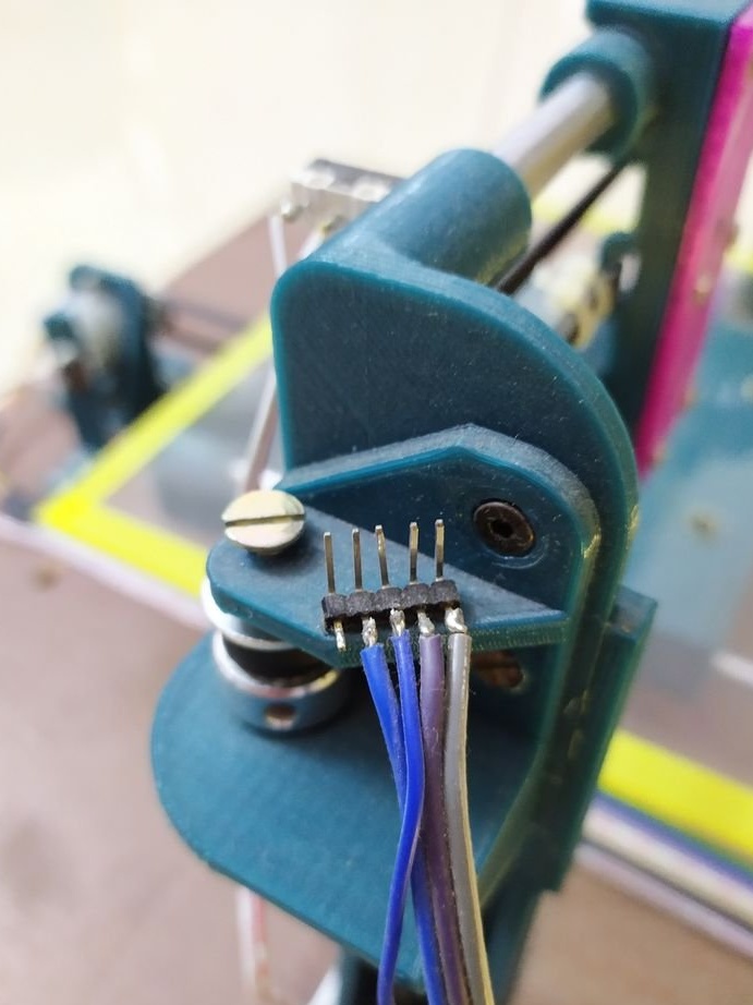
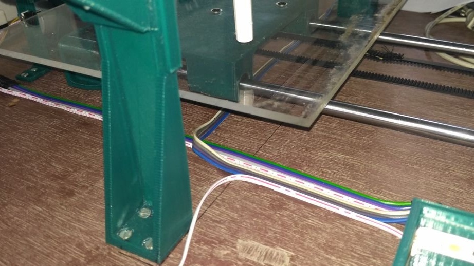
The wires for motors and limit switches are elongated and the connections are insulated.
The wires are glued to the plywood base with superglue.
Here, the boost converter is used only to power the A4988 motor driver chips. Each motor consumes only 150 mA of current.
Step Thirteen: Bluetooth Module
Mounts the bluetooth module.
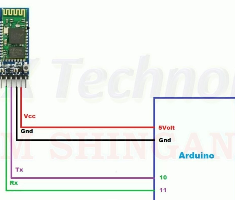
To send and receive data or, in this case, G-codes via the HC05 Bluetooth module, you must first configure the module.
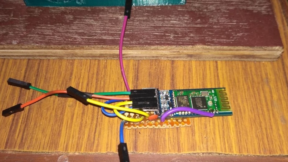
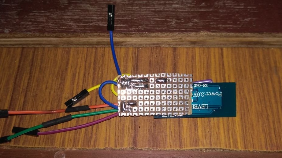
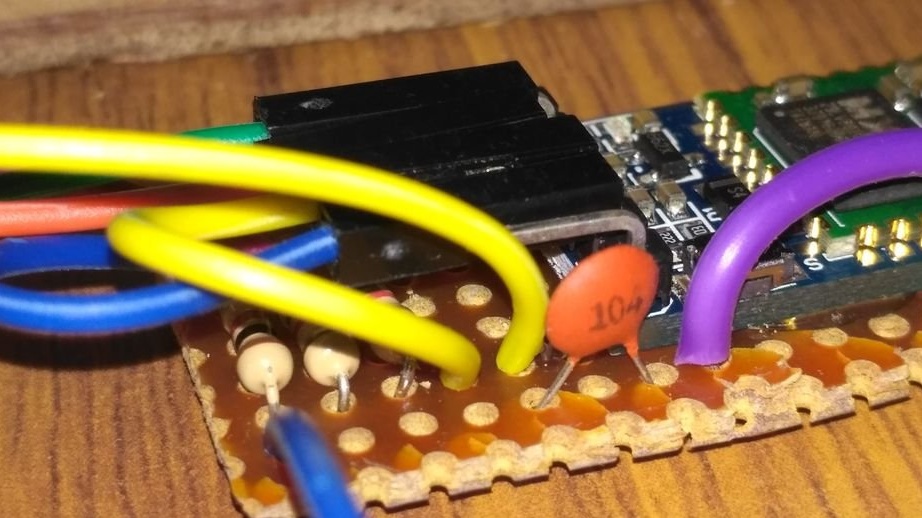
Connect the HC05 module to the Arduino Uno, as shown in the first figure.
Download the code attached to this step to Arduino.
BLUE_P.ino
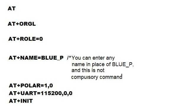
Now enter the codes shown in the second photo.
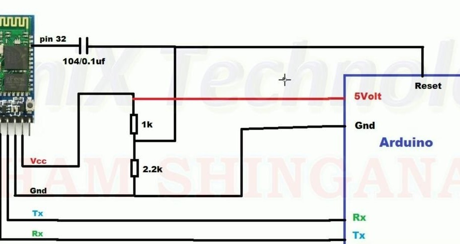
After completing the settings, disconnect the HC05 module from the Arduino that you used for programming, and connect to the Arduino CNC Shield in accordance with the circuit diagram in the 3rd photo.

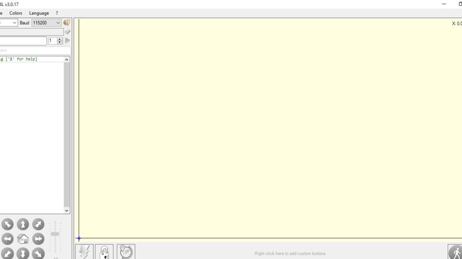
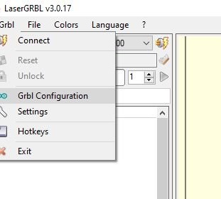
Step fourteen: code and setup
For a laser engraver, the master downloads the code.
GRBL.zip
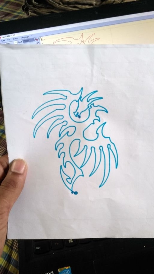
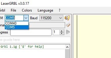
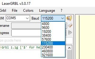
Laser GRBL is one of the best free G-code streamers for laser engravers. It can directly transfer G-codes to Arduino through the som port. It has a built-in tool to convert images to G-codes.
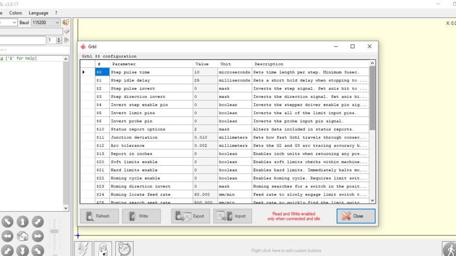
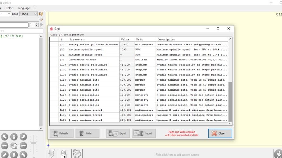
All settings must be done as in the photo, taking into account the following:
Install the catfish port your laser engraver is connected to.
The configuration values can be changed to suit your engraver best.
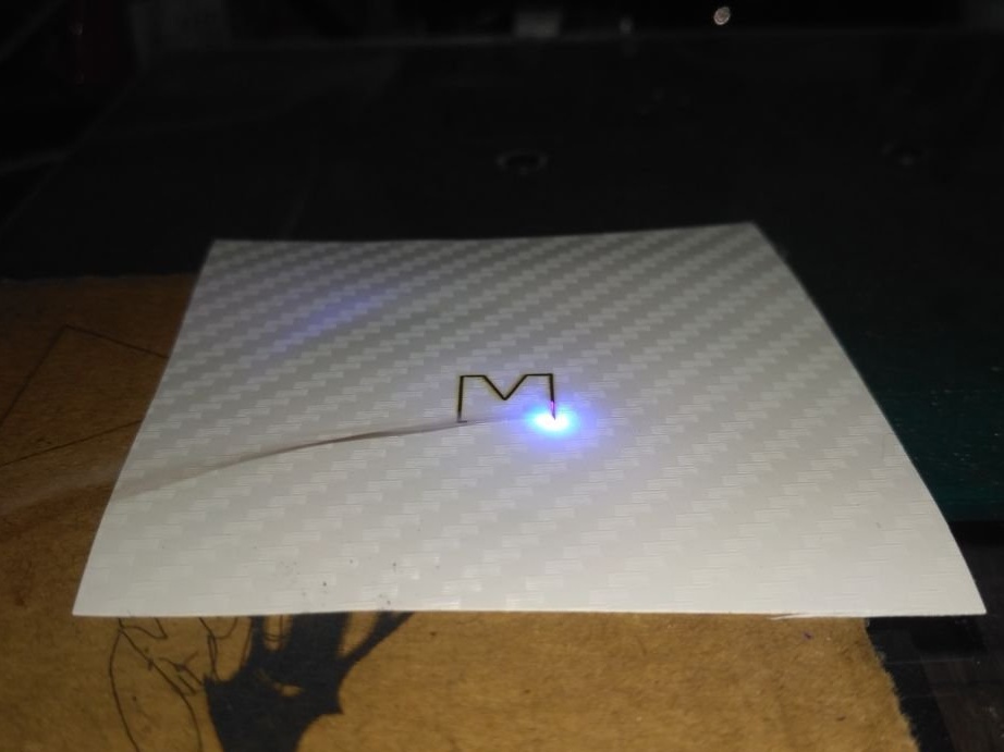
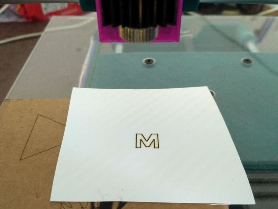
Step Fifteen: Testing
After the laser is connected, it's time to check its accuracy.
There are a few things to check:
Are the X and Y axes moving in the right direction?
Does homing work correctly?
Does the engine skip steps due to high friction or too tight belts.
Are the sizes of the printed images consistent with the sizes indicated in the software. Does the number of steps per mm correspond to the stepper motor used.
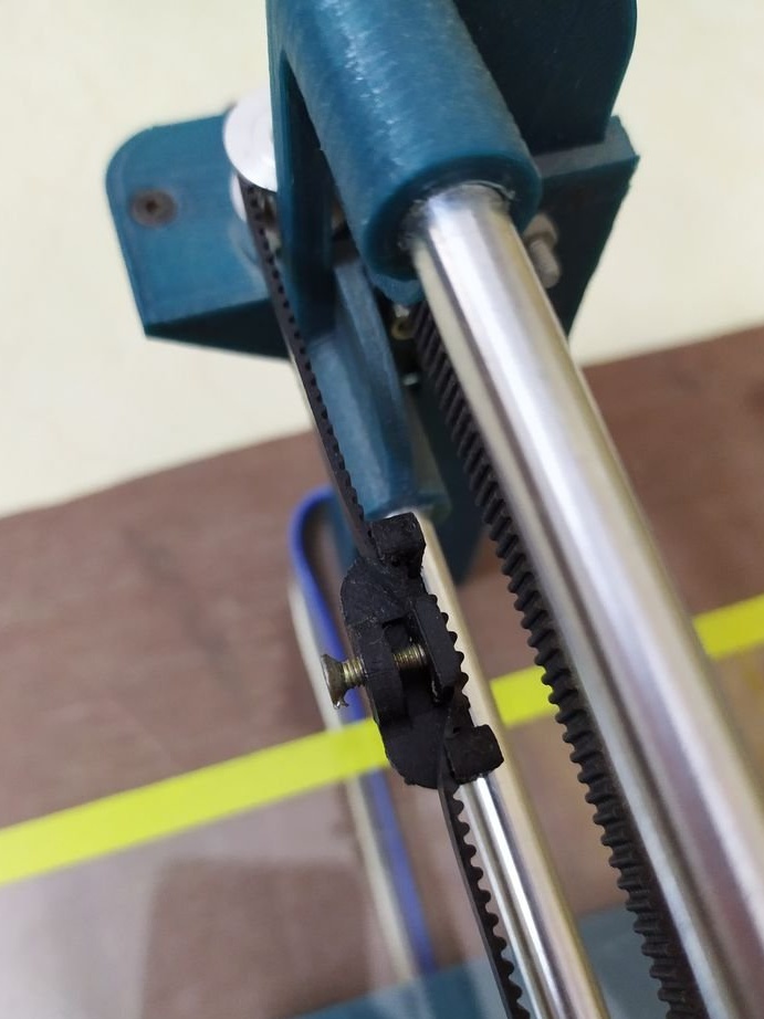
The belt tension can be adjusted using the tensioner. Turn the bolt until the correct tension is achieved.
To check if the engine has steps and the correct dimensions, output a simple continuous geometric figure, for example, a square, triangle or circle. If the laser starts from one point and stops ideally at the same point, this means that your laser has not missed a single step and works perfectly. After the triangle or square is printed, manually measure its size with a ruler and see if it matches the dimensions you specified.
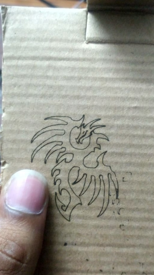
According to the master, he is completely satisfied with the machine.
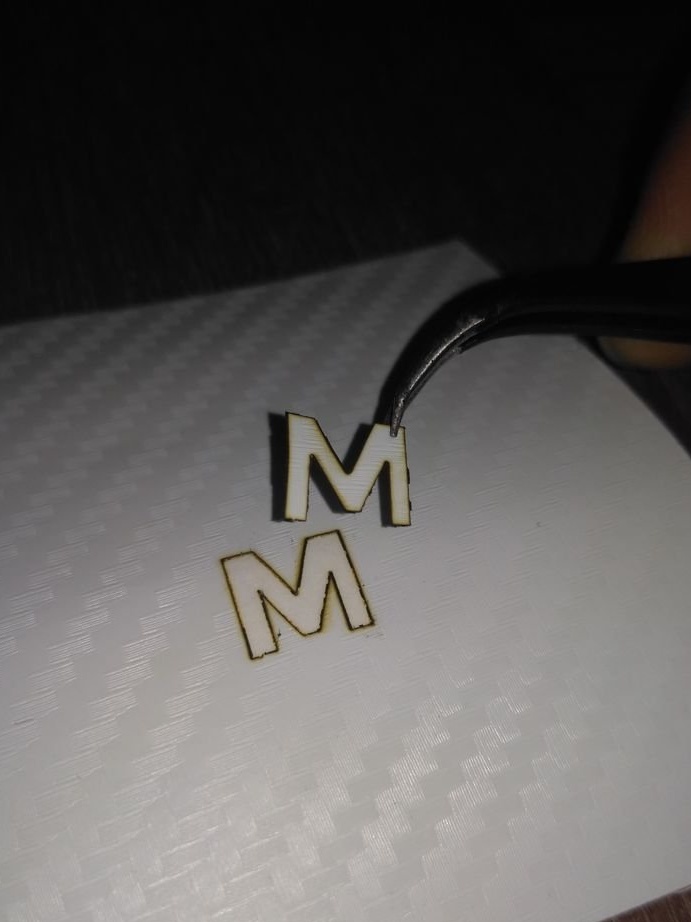
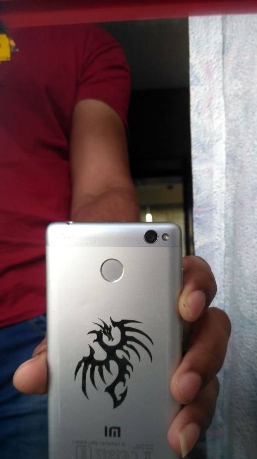
Can be engraved on various materials, such as wood, cardboard, leather, plastic, etc.
Since the engine had about 102 steps per mm, tiny engravings with fine details can be made.
The engraver worked without problems on the USB power supply.