

Video:
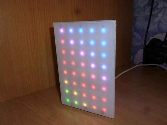
Good afternoon, today I will share instructions for the manufacture of a small table lamp, a night lamp. The light source will be 120 WS2812 LEDs. You can increase the number of diodes or vice versa, make the lamp smaller with fewer diodes. I used an LED strip with a density of 60 diodes per meter. Manages all the ESP8266-12E. Management via html page. So, let's start with the list of necessary:
- ESP8266-12E
- 3.3v voltage stabilizer
- Resistors 10 kOhm, 5pcs.
- Small switch
- Button
- connecting wires
- Matte or "milk" plastic
- Corrugated cardboard
- USB-TTL
- USB connector
- A small piece of plastic tube
- Power supply 5 V, minimum 2 A
- Hot glue gun
- Soldering iron, rosin, solder, etc. etc.
Step 1 Preparation of the base and LEDs.
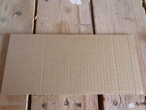
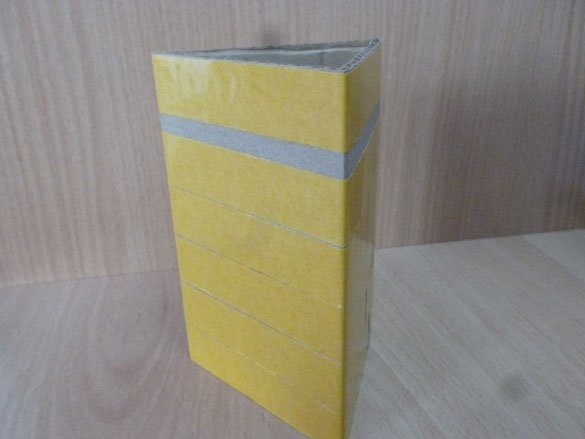
For the base on which we will glue the LEDs, we will use corrugated cardboard. I will write the sizes for the night lamp, which I myself have assembled. If you decide to resize or use a different LED strip, the dimensions will need to be recounted. So, we cut a rectangle measuring 26.5 x 12.5 cm from cardboard:
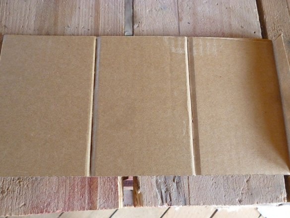
We retreat 1 cm from one edge to connect the parts, and divide the remaining rectangle into 3 equal parts. We cut the top layer of corrugated cardboard so that it can be bent:
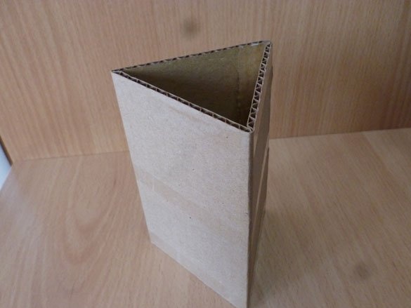
We bend our rectangle, along the slots and glue it, we get a prism:
The adhesive layer of the diode tape is sometimes not enough to fix them well. Therefore, for strength, you can use double-sided tape. Glue it on a cardboard base:
Glue the diodes with lines, start from the bottom line. Glue the first line to the very bottom, step back a bit and glue the next line so that the distance between the diodes of the adjacent lines is 1.6 cm. For the WS8212 tape, the direction of the signal contact must be observed. On the tape, the direction is indicated. Glue lines in one direction:
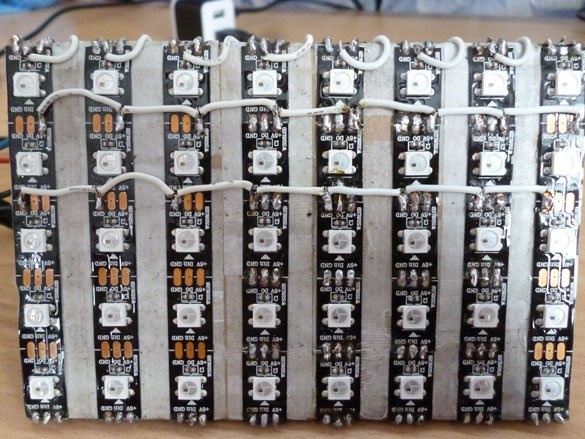
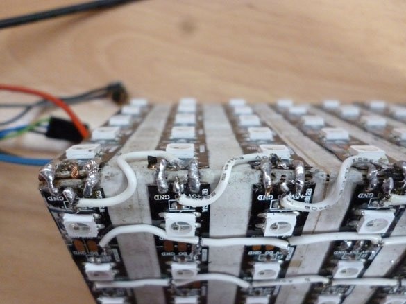
The wires of the +5 and GND power contacts from the first line of LEDs, as well as the wire from the signal signal Din, are routed inside the case. Then we solder Do from the first to Din of the second line and so on.The power contacts (+5 and GND) are soldered in parallel:
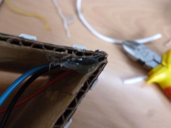
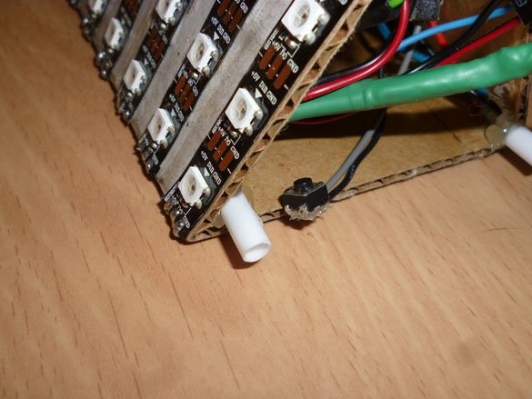
I use trimming plastic tubes, for example, from a balloon on a stick, we make legs 1 cm long to our lamp:
The result should be something like this:
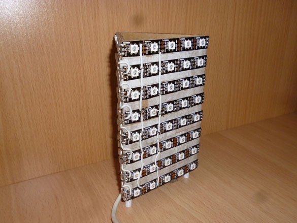
This is one of the options, the form can be anything, everything is limited only by your imagination. For example, a nightlight can be made in the shape of a cone or a cylinder.
Step 2 Prepare the ESP8266 and the power supply.
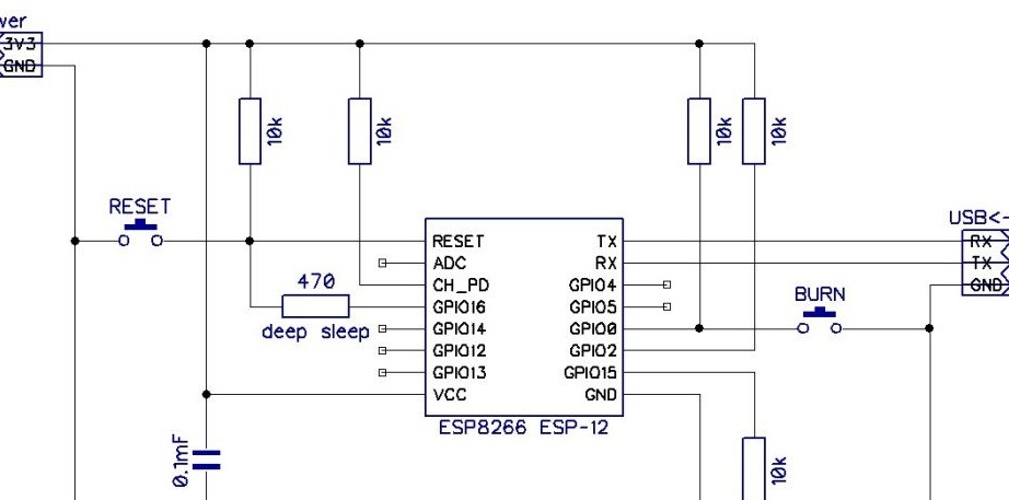
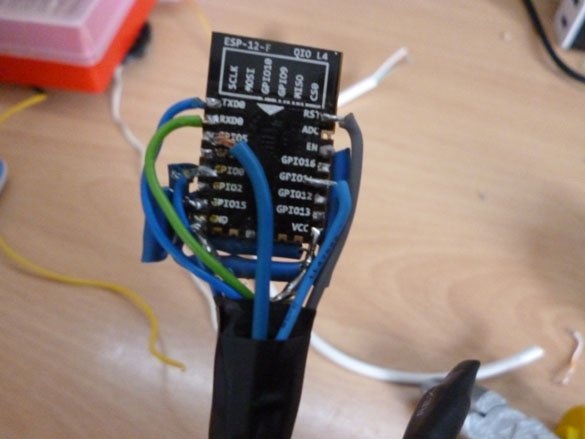
I am using ESP8266-12E, with 4 MB Flash memory. ESP8266 versions with fewer GPIOs can be used. Only one GPIO is needed to control the tape. Flash memory is less than 1 MB, it is better not to take it. For the ESP to work and fill the sketch into it, you first need to make a minimum binding for this board. The binding consists of a switch connected at one end to GPIO0 and the other to GND, which is used to put the module into sketch fill mode. In the normal state, GPIO0 must be pulled up to power via a 10 kOhm resistor. A pull-up to the power supply through the resistor also needs CH_PD, GPIO2. To reboot the module, a button is placed between RESET and GND; to ensure stability, the RESET should also be pulled up to power. A 470 ohm resistor inserted between RESET and GPIO16 is needed to bring the module out of sleep mode. We will not use this mode, therefore a resistor is not required. The output of the GPIO15 module must also be pulled up to GND through a 10 kΩ resistor. The module must be powered strictly from 3.3V. Therefore, we will use a voltage stabilizer. To the input of which we will connect the plus from the power supply, and to the output of the VCC ESP8266. GND I think everything is clear, the main thing is that the GND power supply, GND tape and GND ESP are connected. And don't forget about USB-TTL. RX to TX, TX to RX and be sure to connect the GND ESP to the GND USB-TTL. The scheme is as follows:
Now in the market of radio equipment there is a line of Wemos modules. These are the same ESP8266 modules, only with the necessary harness, voltage regulator, USB-TTL and conveniently output contacts. It is much easier to work with them, you can take these modules, only when filling in the sketch, choose the right board.
We will connect the tape to GPIO5. That is, Din from the first line of the tape is connected to the GPIO5 ESP8266.
In my opinion, you can unsolder all the necessary canopy. When assembled, the ESP8266 will look something like this:
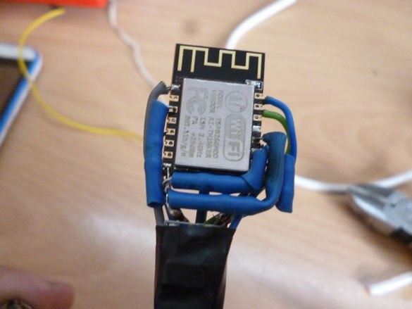
So it turns out compactly and the controller fits easily inside the nightlight:
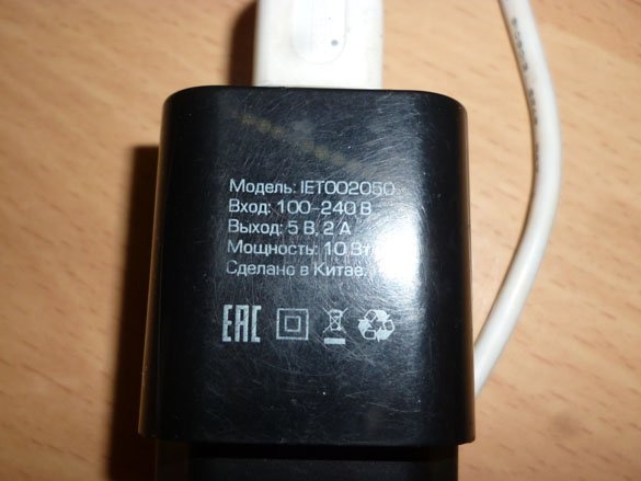
As for the power supply. The WS2812 tape is very gluttonous. If you turn on all three colors, and even at maximum brightness, one LED consumes 0.06 A. Accordingly, 120 diodes is 7.2 A. Well, this is the maximum value. Usually this brightness is not required, in my sketch it costs 10 (range from 0 to 255) and this is enough. I measured the consumption of my nightlight at a brightness of 20. Consumption was in the range from 1.0 A to 1.8 A. For this nightlight, you need to take a power supply with an output current of at least 2.0 A. For convenience, it is better to solder USB to the end of the nightlight power cable, or just take a wire with already soldered USB. The power supply should then be something like this:
Step 3 Prepare the environment and fill the sketch.
For proper operation and sketch filling, it is necessary to prepare a programming environment. We go to the site and download the latest version Arduino IDE.
Sketch tested on latest version Arduino The IDE that was at the time of writing was -1.8.10. If you chose the installer, first install the programming environment, if you downloaded the archive, just unzip it to a place convenient for you.
Now you need to add the ESP8266 board and its modifications to the Arduino IDE. We start the programming environment, select the “File” menu item in the “Settings” list that opens. Select the item "Additional links for the Board Manager." Insert the link to download and install the ESP8266 extension:
http://arduino.esp8266.com/stable/package_esp8266com_index.jsonNext, select the menu item "Tools" and go to the "Board Manager". In the search bar for the board manager, enter “ESP”, select “esp8266 by ESP8266 Community”, and install the latest version. At the time of writing, this is 2.5.2. We are waiting for the installation to complete.
I used the Adafruit neopixel library to control the LED strip. To install this library, select the “Sketch” menu item, go to “Connect the library” and select “Manage libraries”. In the search bar that opens the menu, enter "Adafruit neopixel", select and install the library of the same name.You will also need the ArduinoJson library, you can also find it by using the search for the Library Manager.
An html page is used to control the nightlight, there are also several pages for configuring the module. To record these html pages, as well as everything necessary for their proper operation, we need an additional utility. Download the archive located below and unpack it into the “tools” folder located in the installation location of the Arduino IDE:
Download archive
After all the manipulations, you should restart the programming environment.
Now edit the sketch. Open the sketch:
Download sketch
You need to edit the following lines:
String _ssid = ""; // SSID of the access point to which you want to connectIn this line, between quotes, enter the name of the access point to which the nightlight will try to connect.
String _password = ""; // network passwordHere, also between quotation marks, specify the password from the access point to which the nightlight will try to connect. If you do not want the ESP to connect to some kind of access point, just leave these paths untouched.
String _ssidAP = "Treygolka"; // SSID AP in access point modeThe line indicates the name of the access point that the ESP8266 will create.
String _passwordAP = "12051005"; // Access Point PasswordPassword of the created access point.
It remains to fill in the sketch and load the html page into ESP8266.