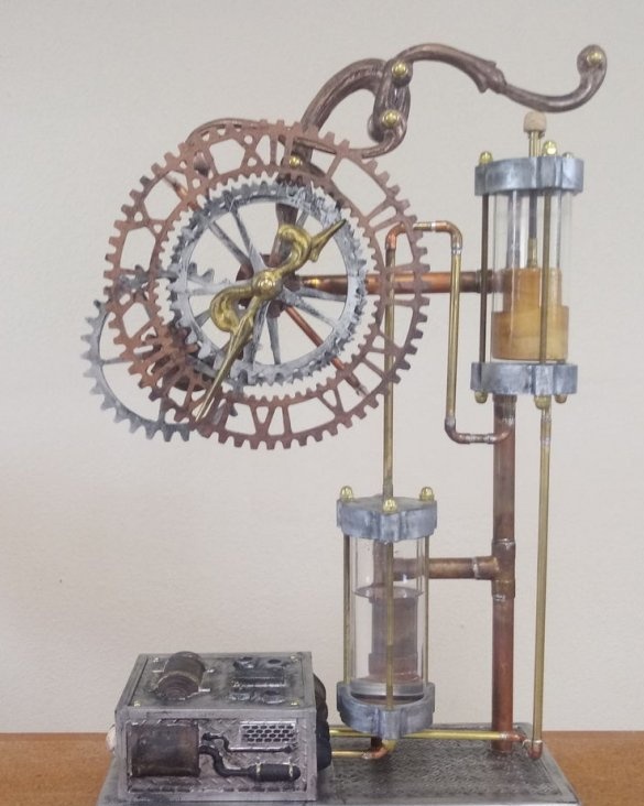
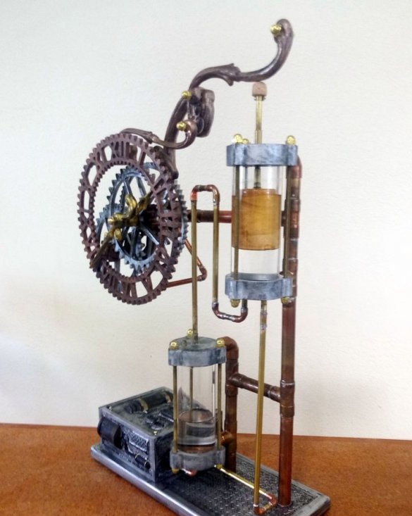
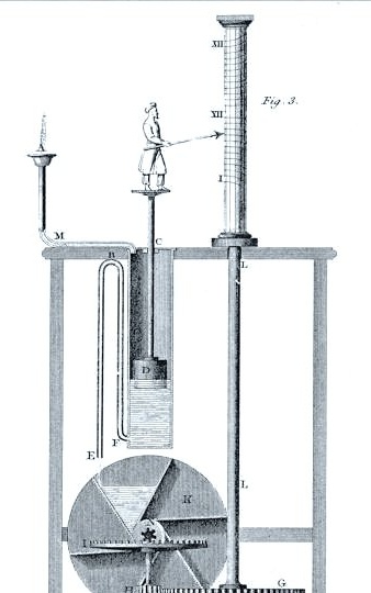
The word "clepsydra" comes from the Greek meaning "thief of water." So called a water clock since the time of the Assyro-Babylonians and ancient Egypt. Such watches were used until the XVII century.
A constant stream of water fills the chamber, and the siphon periodically drains it. This action moves the float up and down, and activates the clockwork.
The master combined ancient knowledge and modern technology in his homemade.
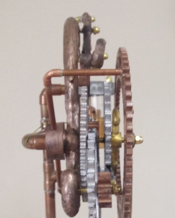
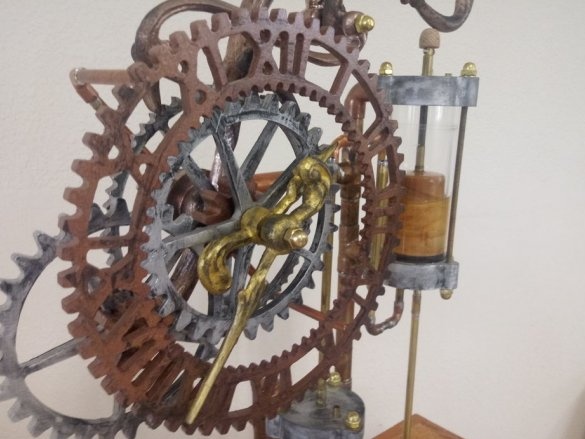
It uses an electric pump for continuous water supply. The float in the siphon is connected by a lever with a ratchet mechanism and a dog mechanism. The ratchet wheel has 60 teeth and the cycle is one minute, then the ratchet directly sets the minute hand in motion. The gear set drives the hour hand. The microcontroller monitors and regulates the flow of water to maintain an accurate one-minute cycle and accurate time.
The master used Carvewright CNC to cut non-metallic parts and a computer using Carvewright Designer software to design these parts. Carvewright uses its own file formats, so these files are useless if you do not have a Carvewright machine. Instead of encoded files, the wizard included plans for wheels and gears that can be cut using a band or spiral saw. Of course, you can resize to fit your needs.
Tools and materials:
-Copper tubes and fittings with a diameter of 3/4 ";
-Soldering accessories;
- Brass and / or copper tubes;
- Brass sheet;
- Copper fittings 1/4 "90 degrees;
-Acrylic pipes;
- Sealing rings;
-Vinyl tubes;
- Brass rod with thread;
- Brass nuts and washers;
-Board;
-Baltic birch plywood;
-Water pump;
-12V DC power supply;
Microcontroller MSP430;
-Electronic Components;
- Brass screws;
-Spray-paint;
-Acrylic paint;
-CNC machine;
Step One: Frame and Base
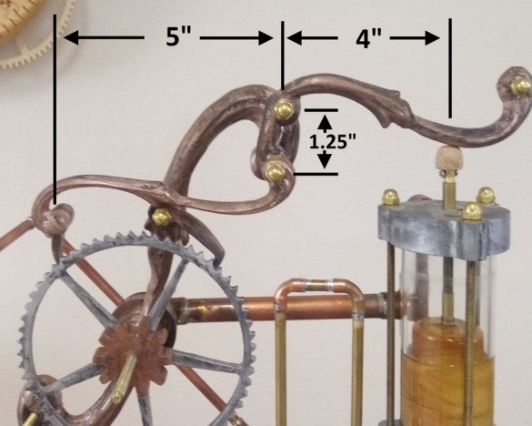
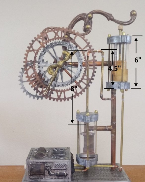
The wizard began with the development of the frame. He used 3/4 inch copper pipe and fittings. For the base, a 3/4 inch larch was used.
The photograph shows some critical dimensions for placing levers and shafts.
Step Two: Water Chambers
To make water chambers, the master used acrylic cylinders with a diameter of 2 inches. The end caps were carved in wood and painted with metal paint. Then he covered them with black acrylic paint and wiped them with a paper towel to obtain this shade.
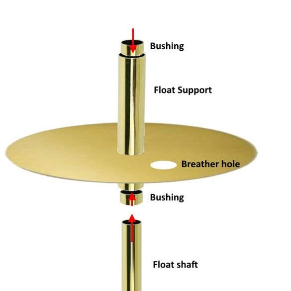
The disks were cut from a brass sheet and brass tubes for connecting water were soldered to them. O-rings from local seal the joint between acrylic and brass. End caps are fastened with a brass threaded rod.

Step Three: Lever and Dogs
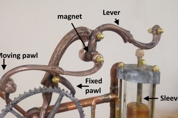
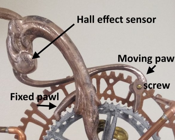
One end of the lever abuts against the stem of the float chamber, the second is connected to the dog. Within 1 minute, the rod lifts the end of the lever up, and the dog turns the gear. At the same time, the Hall sensor integrated in the housing signals one revolution.
A fixed latch prevents the ratchet wheel from moving backward.
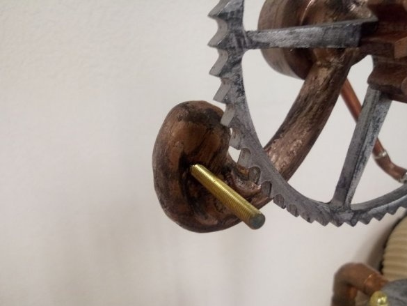
Please note that the tip of the movable dog is fixed with a screw, which allows you to adjust the tip.
There is a sleeve on the float shaft. This sleeve limits the stroke of the float, so that a moving latch moves only one tooth.
Step Four: Float
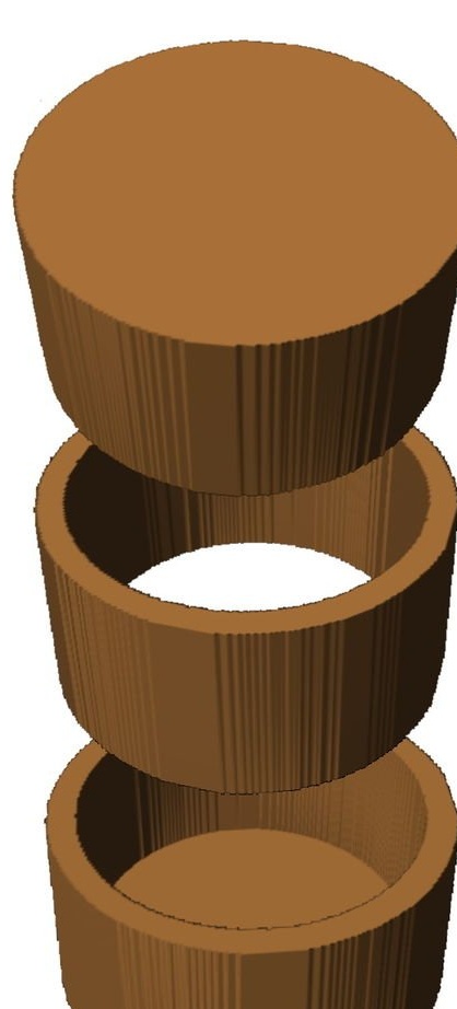
The float is made of wood and then coated with a transparent epoxy resin.
Step Five: stock
The rod rests at one end on the float, and the other on the lever.
Step Six: Siphon
It is important to choose the right diameter and length of the tubes. On the right tube, water enters the upper chamber and raises the float. When the mass of water reaches a critical level, the siphon effect is triggered, the whole mass of water rushes through the left tube into the lower chamber.
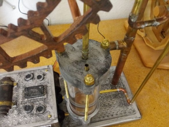
For the first filling of the tank with water, a tube is installed in its upper part.
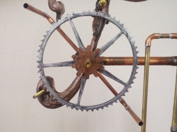
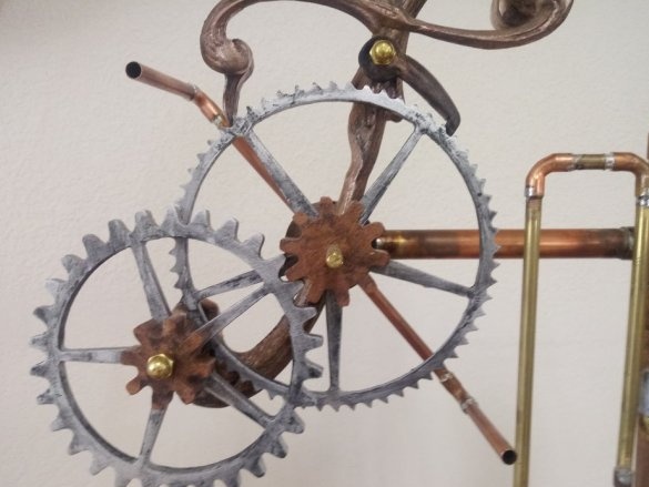
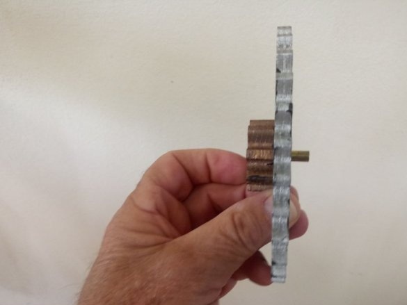
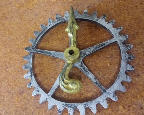
Seventh step: gears
Below you can download the file for self-manufacturing gears.
Steampunk style wooden parts templates.pdf
The master used a brass rod for the shafts. The stopper is also made of a brass rod.
It has 30 teeth in the intermediate wheel, the gear has 8 teeth.
A 32-hour gear is set to an hour hand.
The minute hand is attached to the shaft of the clock gear.
Step Eight: Pump
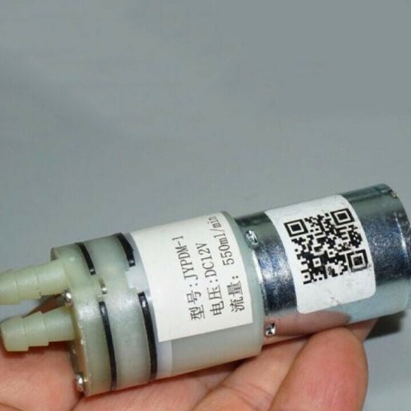
A small 12-volt diaphragm pump is used as a pump. It runs slower at lower voltage. In this way, the pressure is regulated.
Step Nine: Electronics
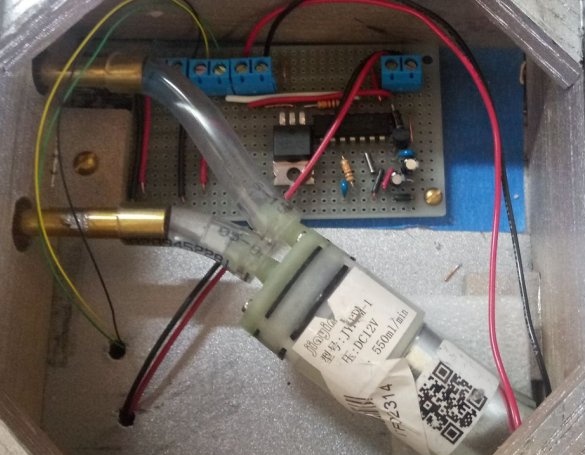
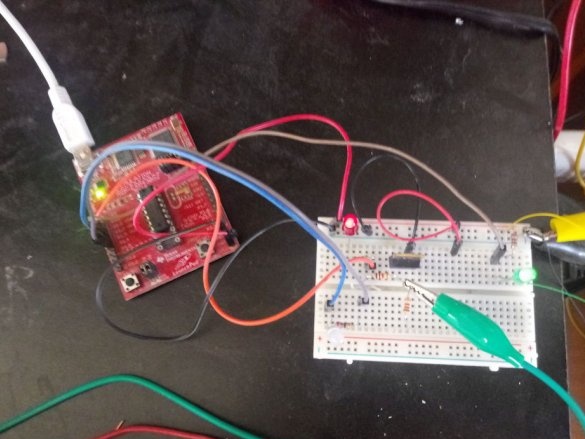
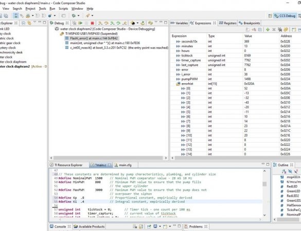
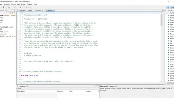
For program control, the wizard uses the Texas Instruments MSP430 microcontroller. He used the MSP430 Launchpad to develop hardware and software. A software development system called Code Composer Studio is included and can be downloaded from the Texas Instruments website.
Full use of Code Composer Studio is beyond the scope of this guide, but there are tutorials and training information from other sources, particularly Texas Instruments.
The launchpad connects to a PC via USB. The wizard wrote the software on a PC, downloaded it to Launchpad and used various debugging tools such as one step, breakpoints, variable checking, etc.
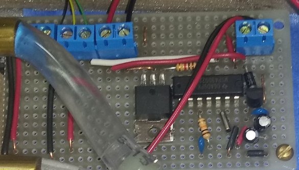
To control the pump, a MOS transistor, a Hall sensor and LEDs for tuning are installed.
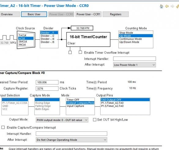
On the launch bar there is a clock crystal with a timer for accurate time synchronization. The timer is used both for measuring the time of siphon failure and for supplying the desired pulse length to the pump. An additional LED connected to the motor indicates PWM operation.
Step Ten: Software
The software is written in C. It uses a modified PID - proportional, integral, differential - controlled algorithm. In each cycle, the time that actually took the cycle is compared with an ideal time of 60 seconds. The difference is called a mistake.Error are used to adjust the pulse duration.
These are the watches made by the Master.

