
In carpentry, when it comes to making all kinds of of furniture, as well as boxes, boxes, caskets, the author often resorts to the help of the slots, since they give a damn strong connection. In addition, this method of joining wooden elements greatly saves time.
However, for splined joints, you need to have a considerable amount of finely chopped wood material, which in itself is a problem. As you know, it is necessary to take into account not only the thickness of the blade, but also the distance between the disk and the stop.

In this article, the author of YouTube channel Make Things will tell you how to create device for a circular saw facilitating this process.
Materials
- Boards
- Screws, wood screws, washers, wing nuts
- Springs
- Furniture hinges
- Steel ruler
— Two-component acrylic adhesive
- masking tape
- PVA glue.
Instruments, used by the author.
— A circular saw
— Japanese saw
- Drilling machine
— Glue gun
- Drills for wood, countersink
— Band-saw
— Clamps
— Miter saw
— Forstner Drills
- Scissors for metal
— Electronic caliper
- Chisels
- Vise, hacksaw, pliers, pliers, awl, rasp
— Svenson Square, ruler, pencil, marker, screwdriver.
Manufacturing process.
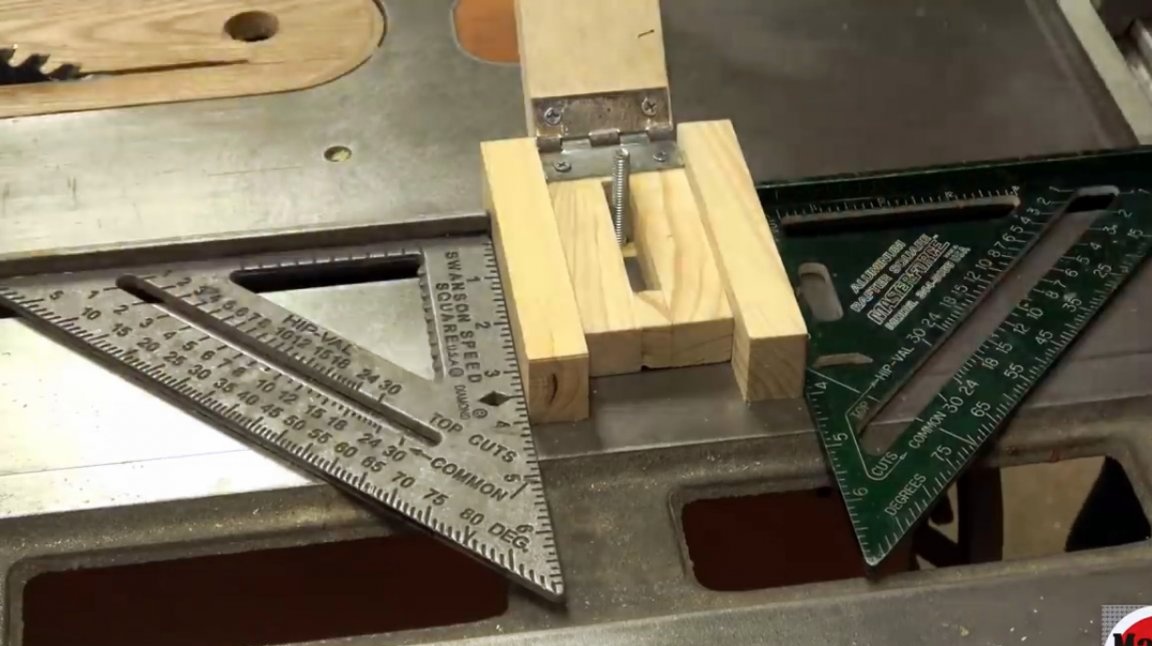
Some joiners push the board against bolts or bearings. But the author rejects this method because of its low accuracy. Instead, he offers a special tool for the manufacture of thin wooden planks.
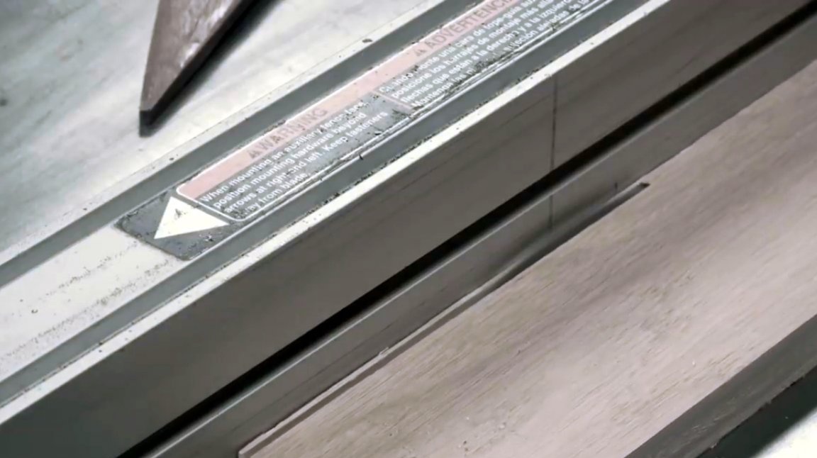
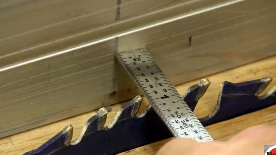
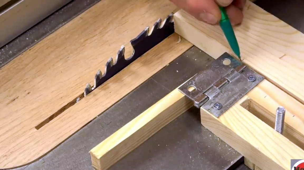
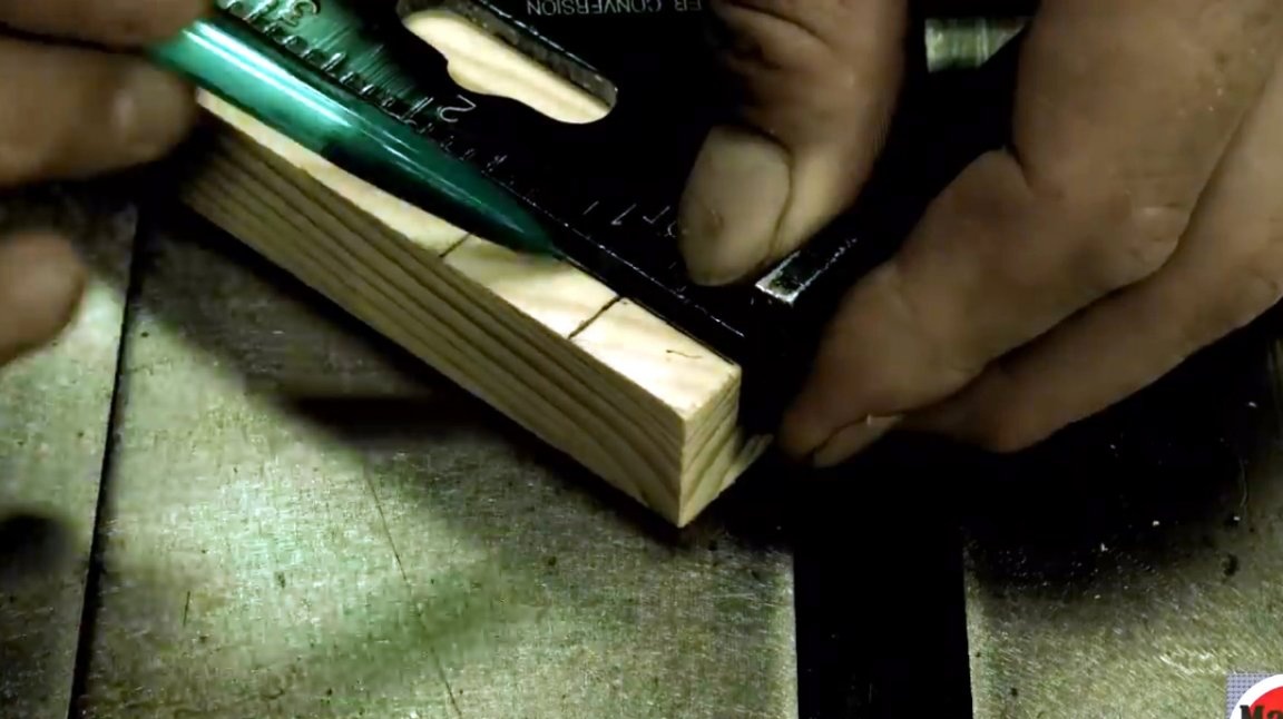
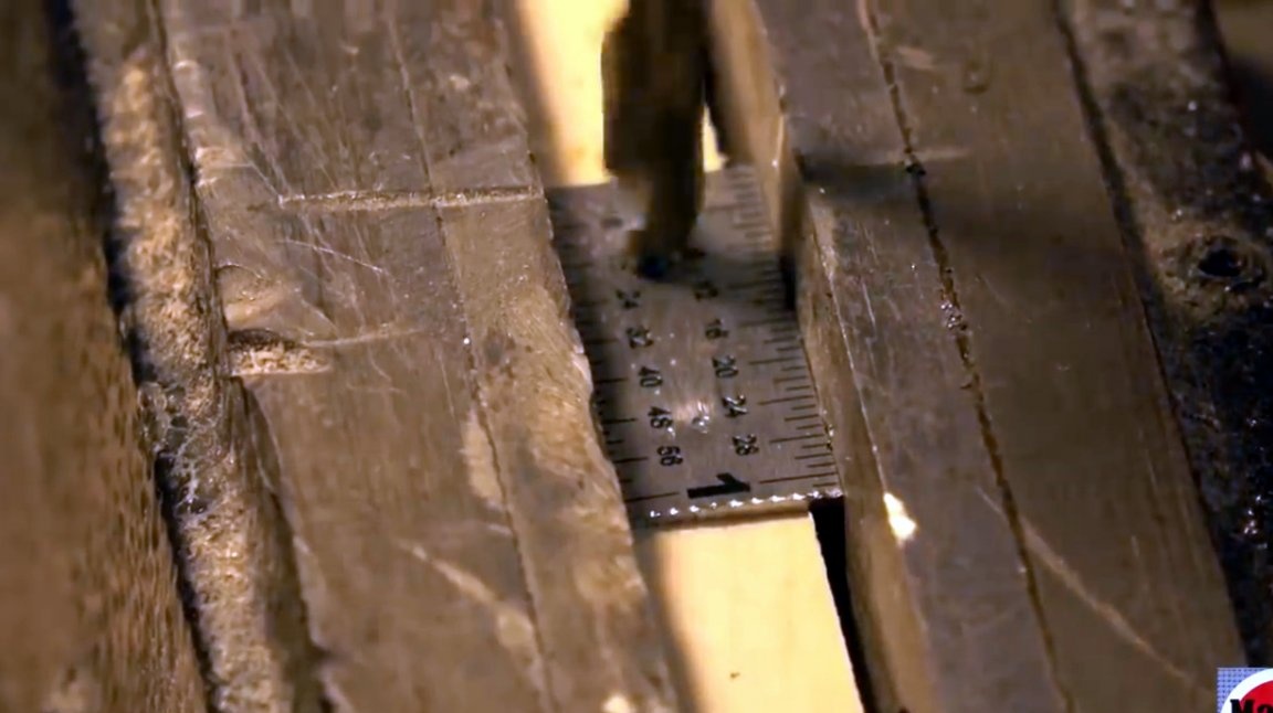
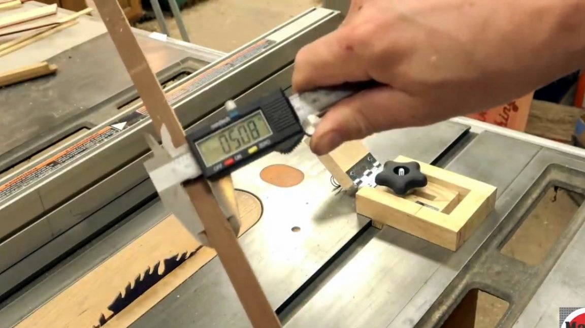
And he begins by measuring the width of the P-track (guide). The width of the saw blade is also measured.
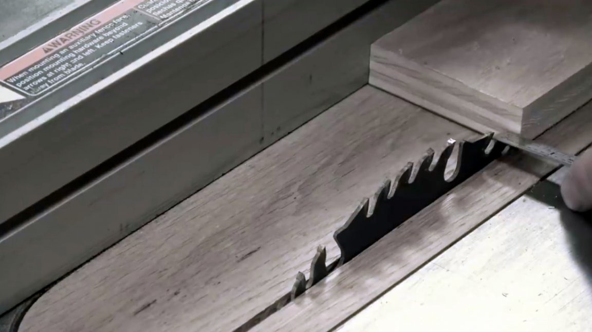
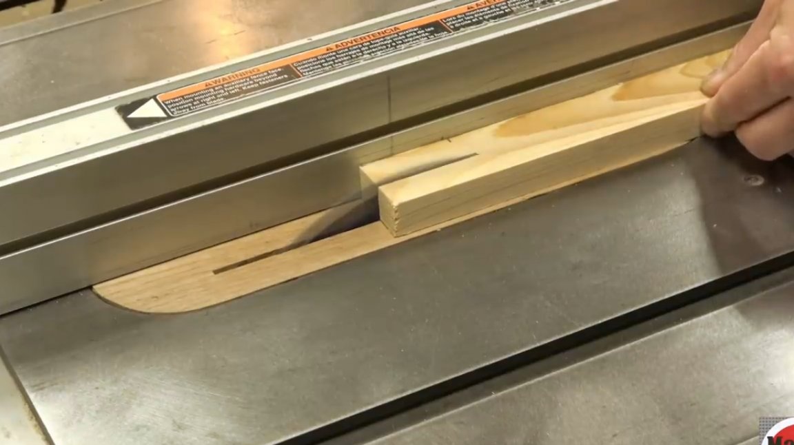
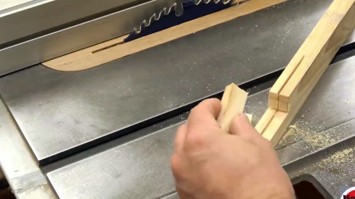
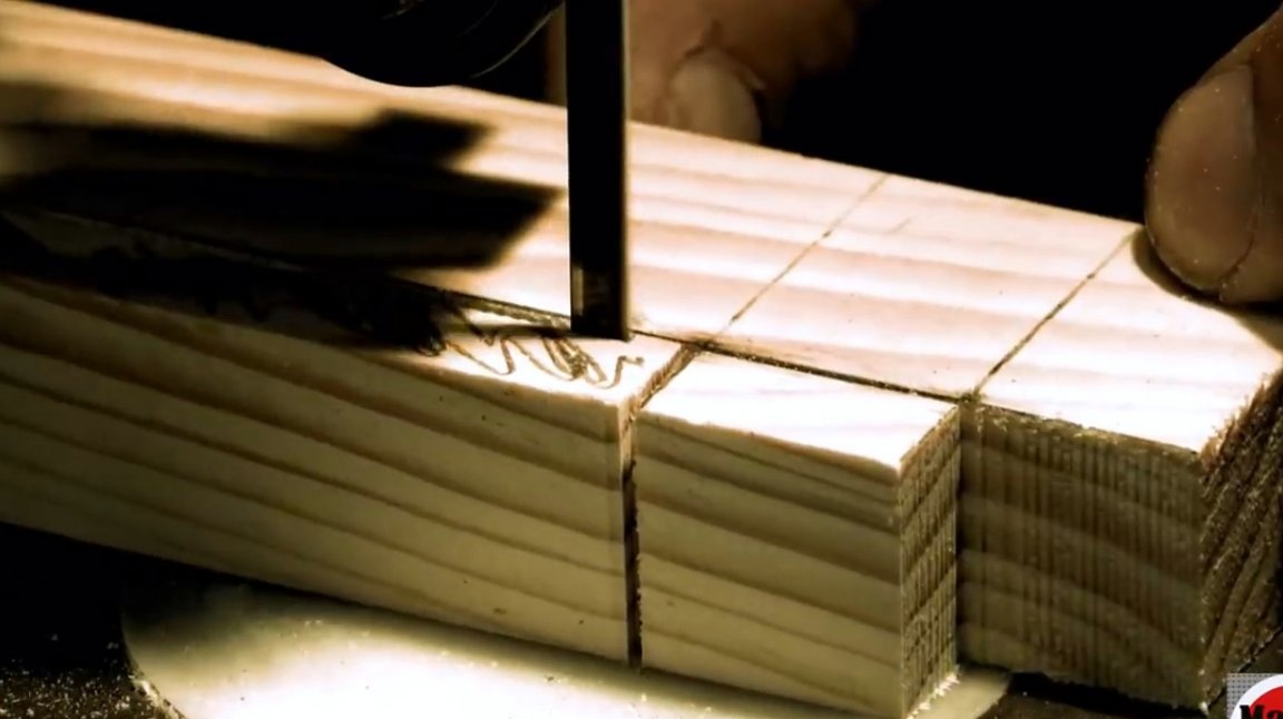
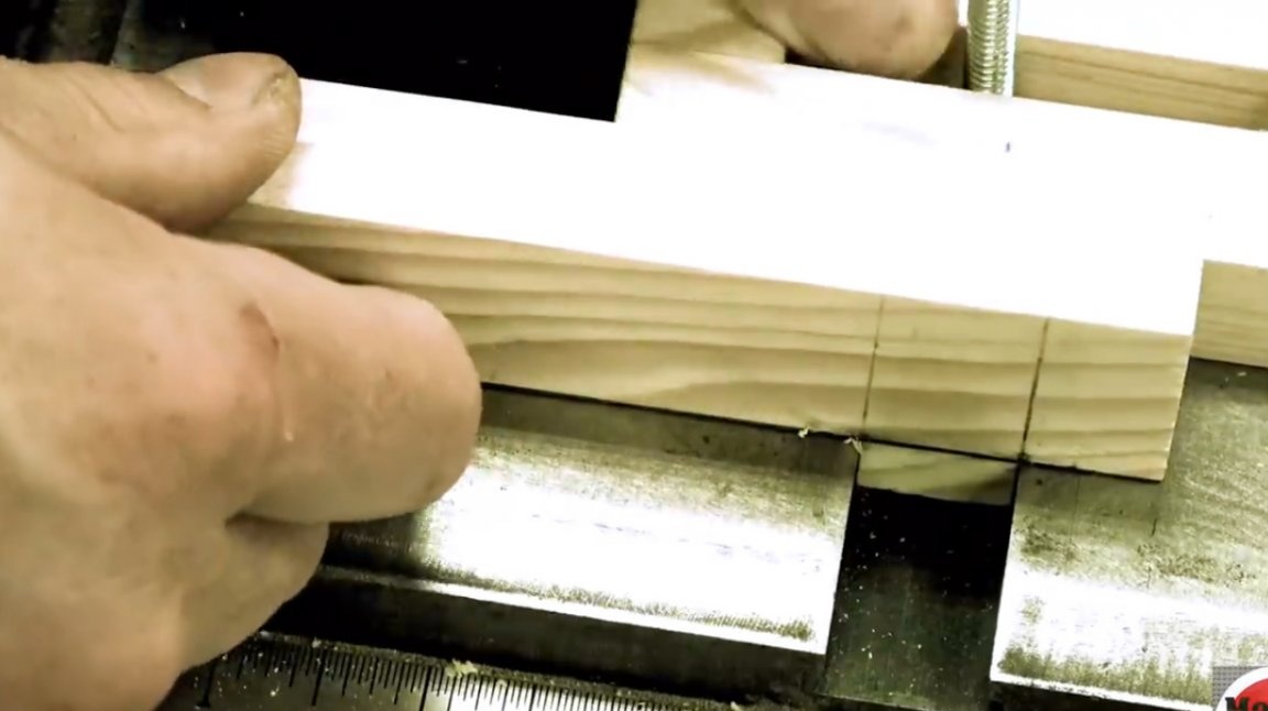
And then cuts a gap in a wooden beam, turns the beam over on the other side and makes a second slot perpendicular to the first, each time turning off the saw.
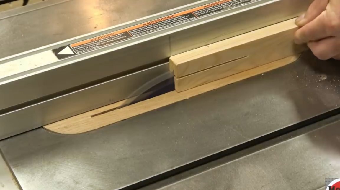
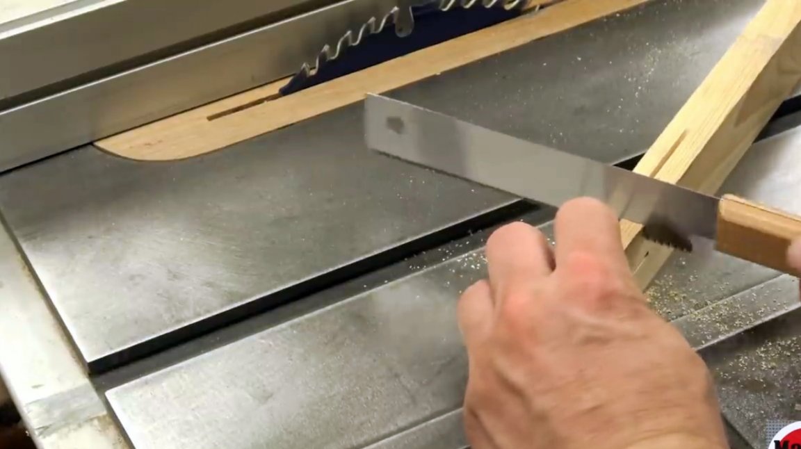
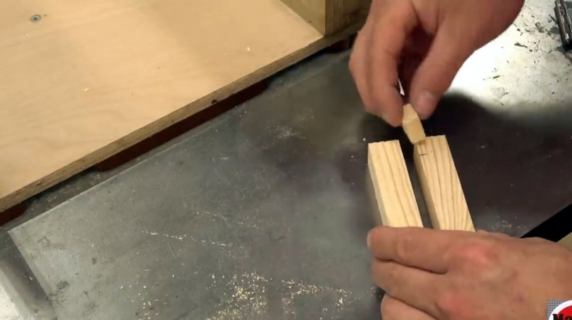
Then, with a Japanese saw, he cuts the beam along the length.
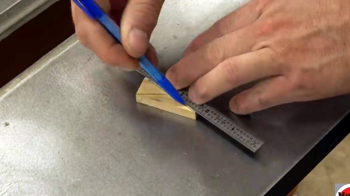
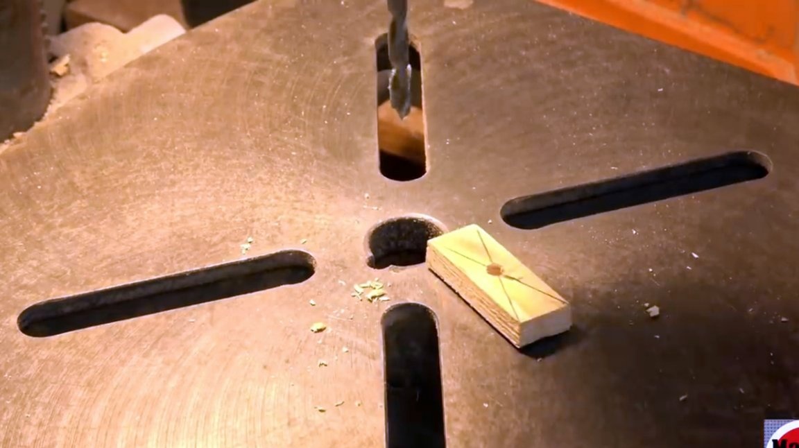
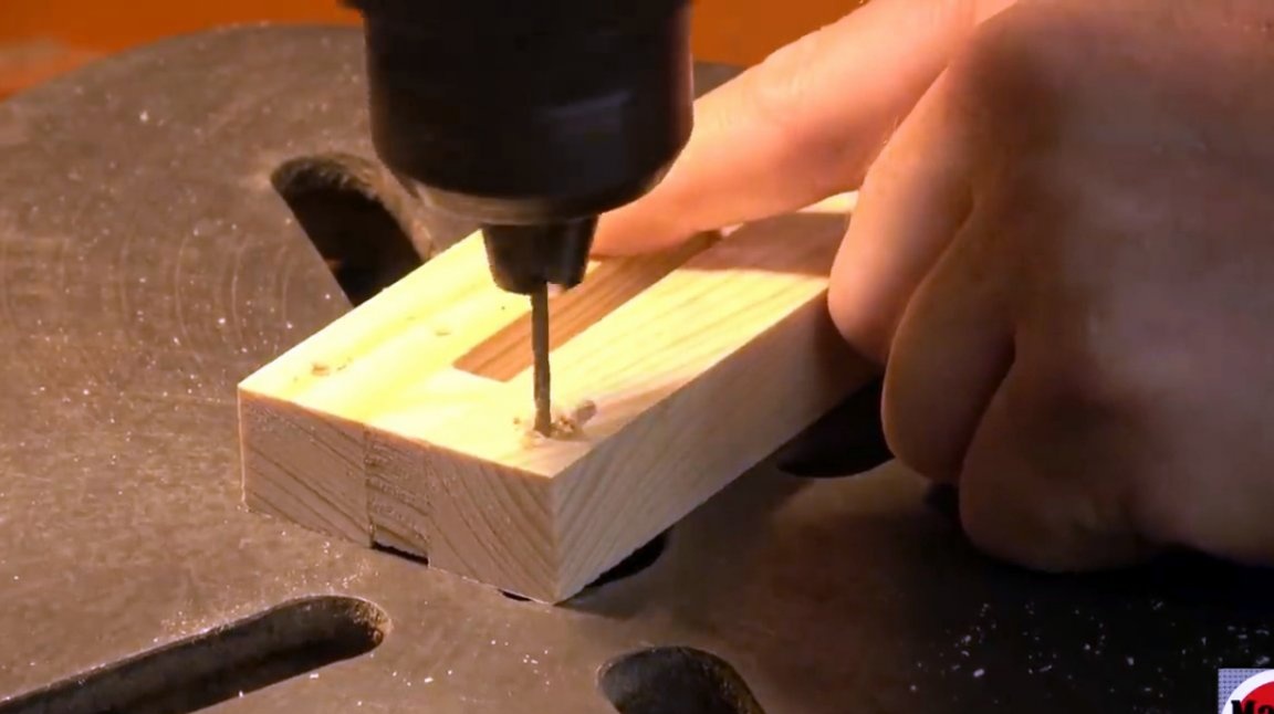
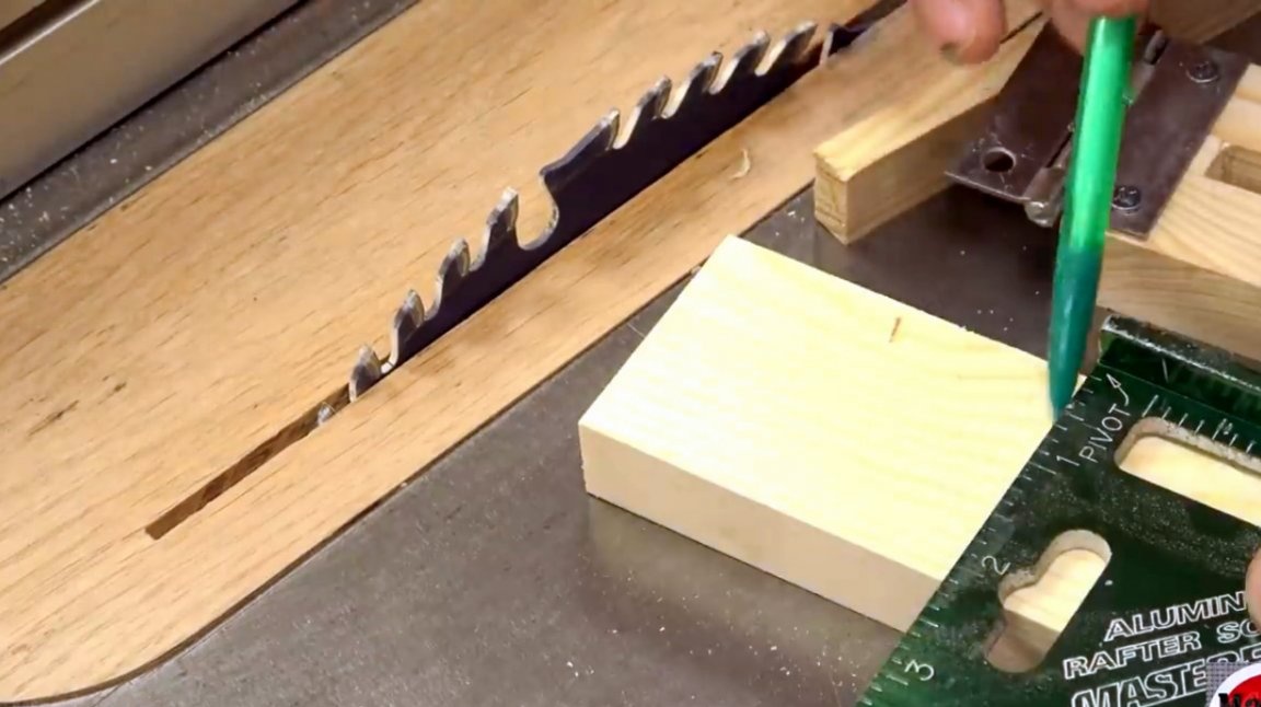
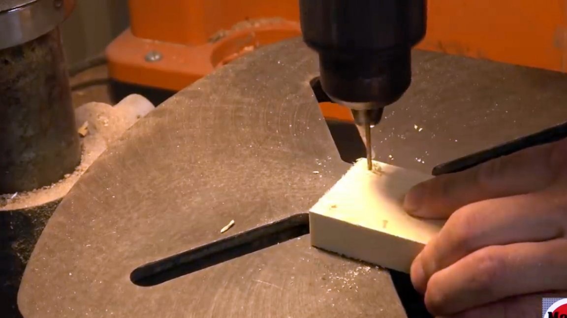
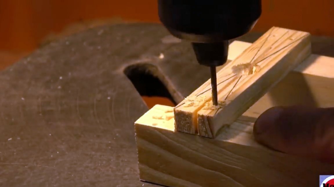
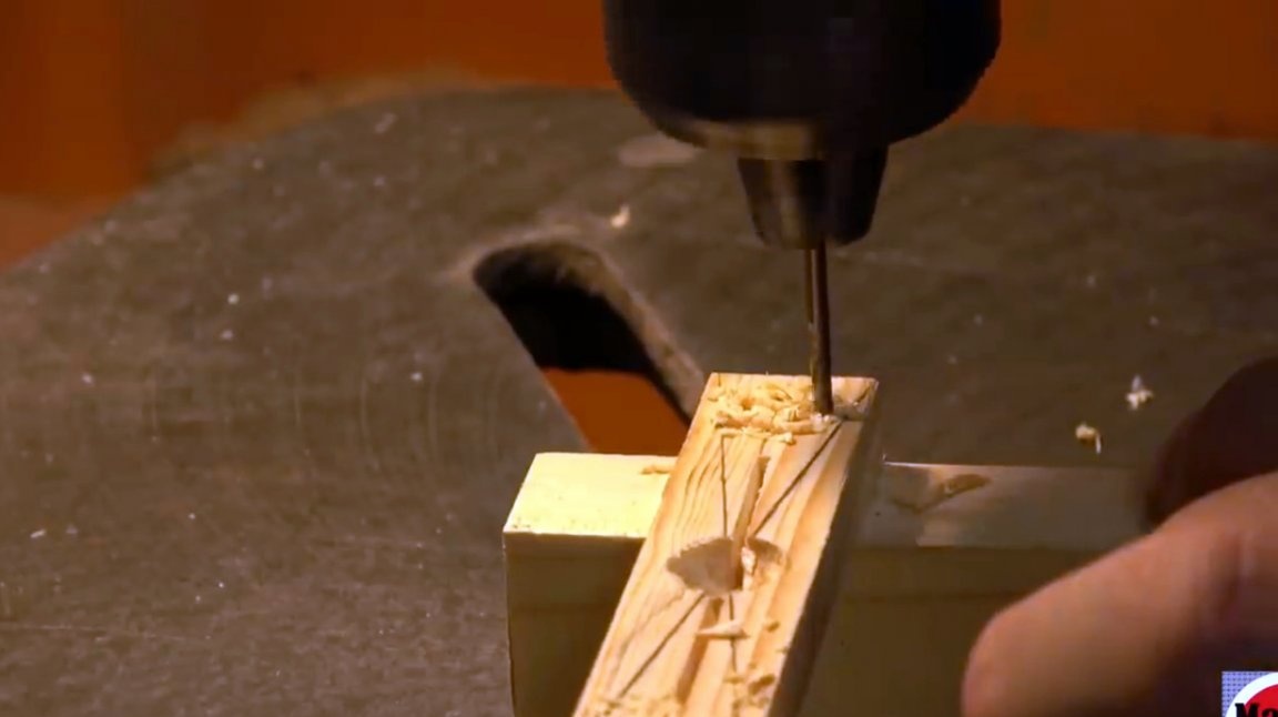
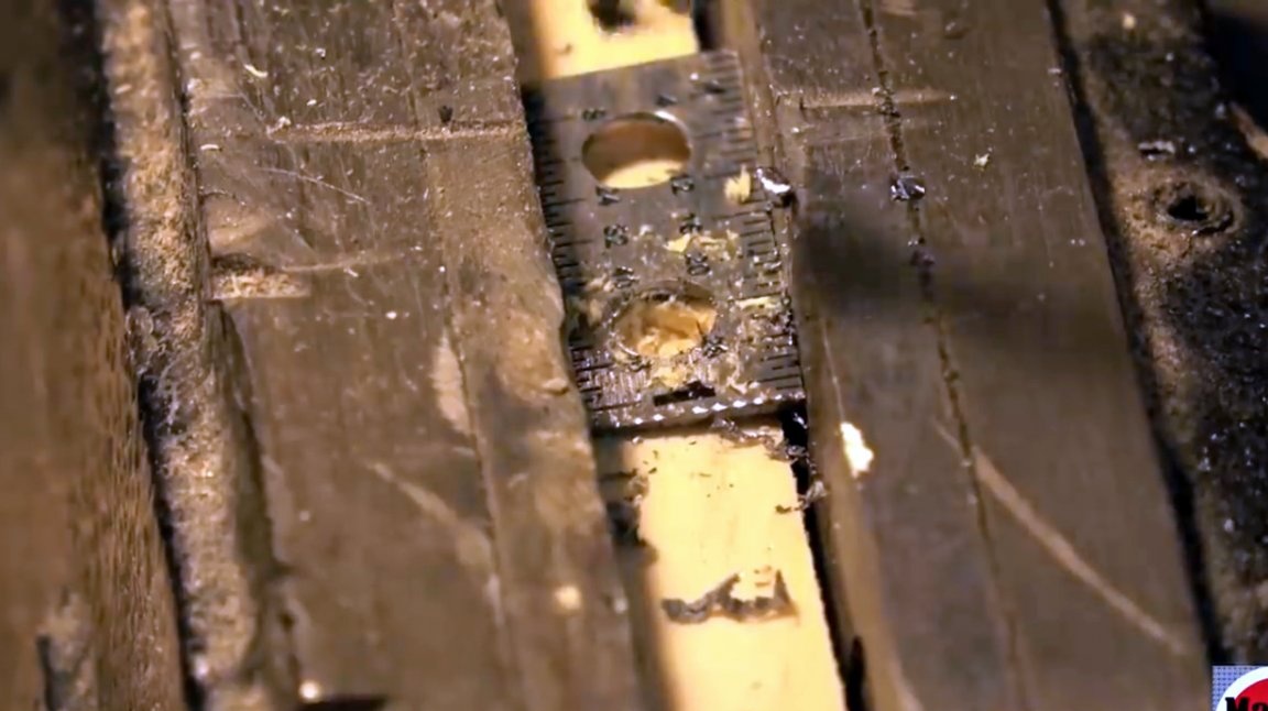
On a small cut piece, the master marks the center, drawing two diagonals.
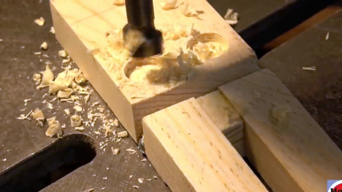
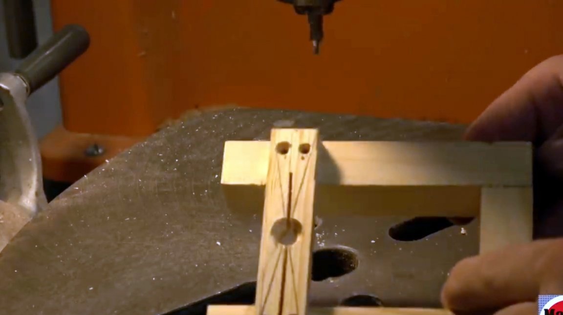
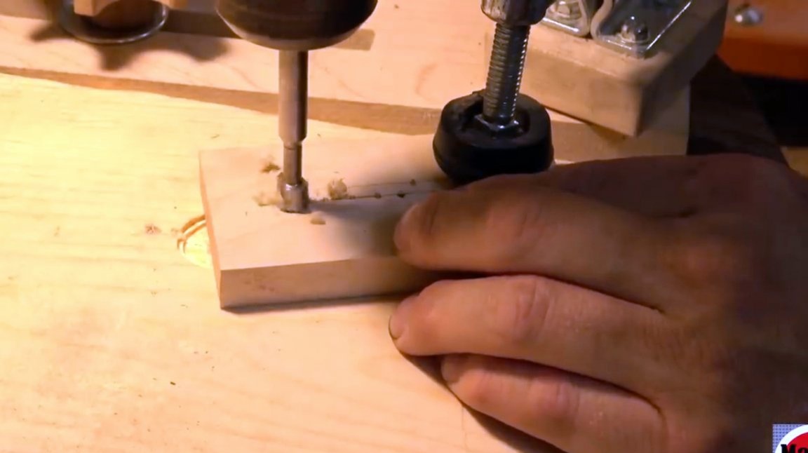
At the place of their intersection, he makes a through hole on the drilling machine, which then countersinks.
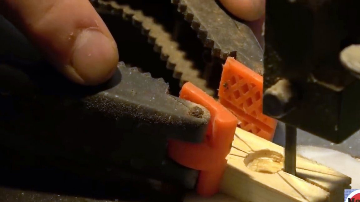
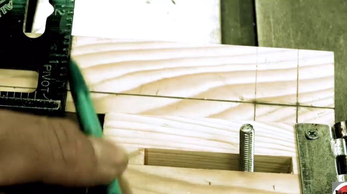
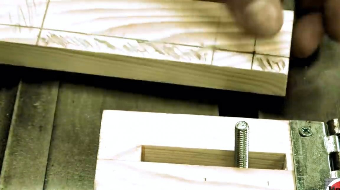
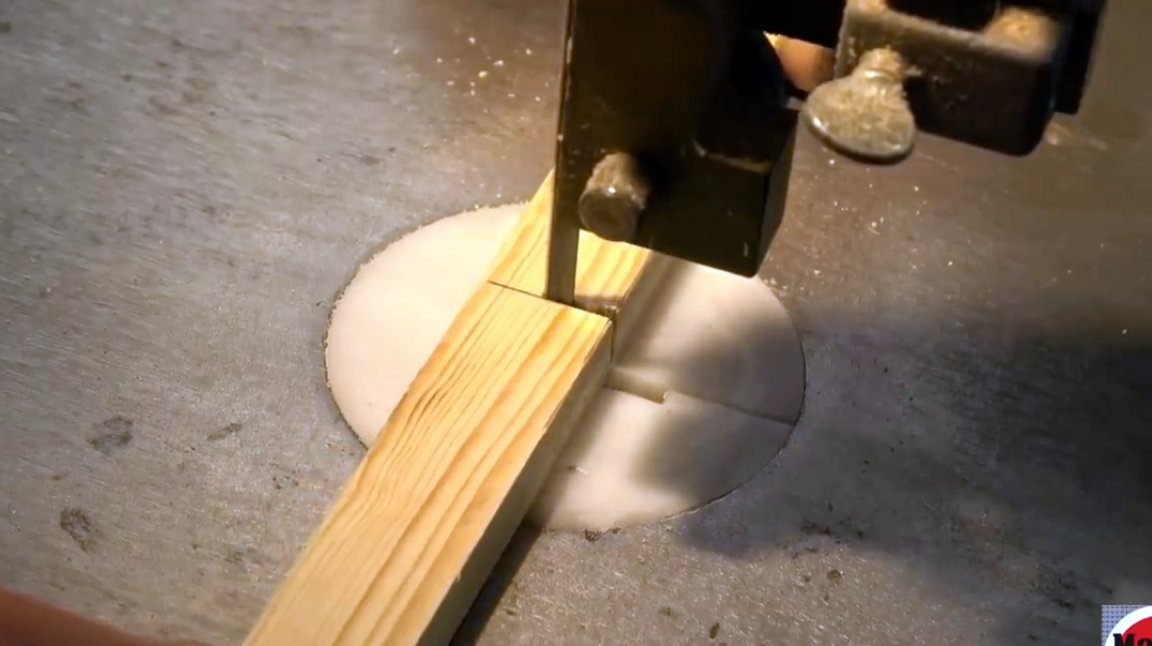
Next, with a band saw, the part is cut through approximately ¾ of the entire length. This will be an expansion unit, thanks to which the device will be fixed in the P-track.
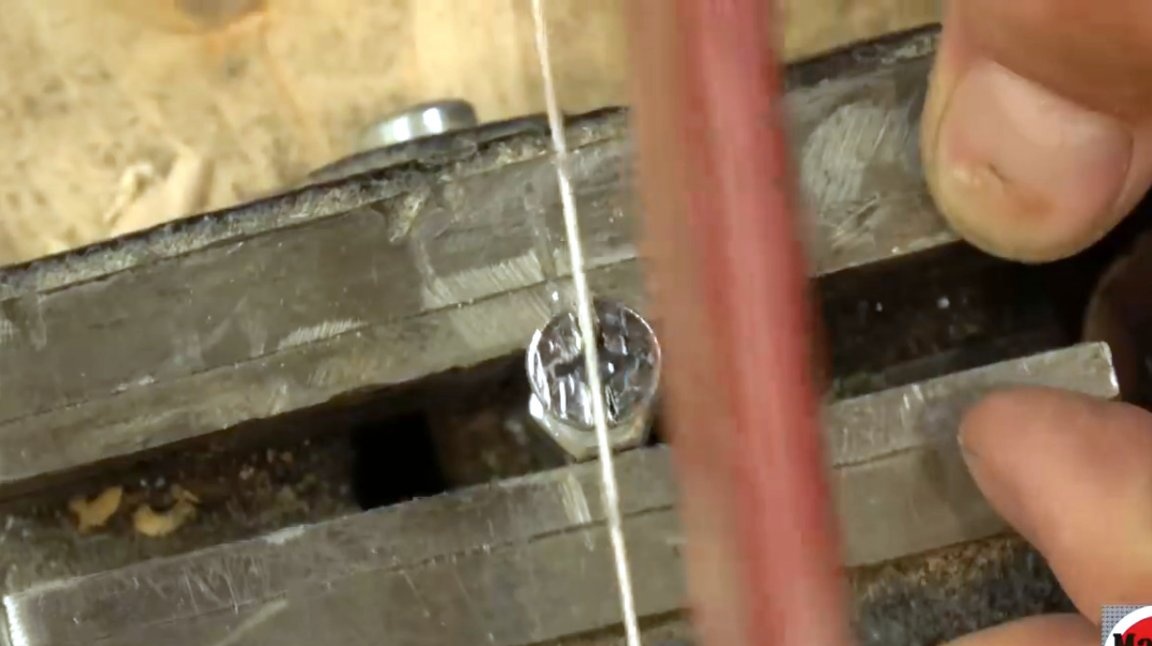
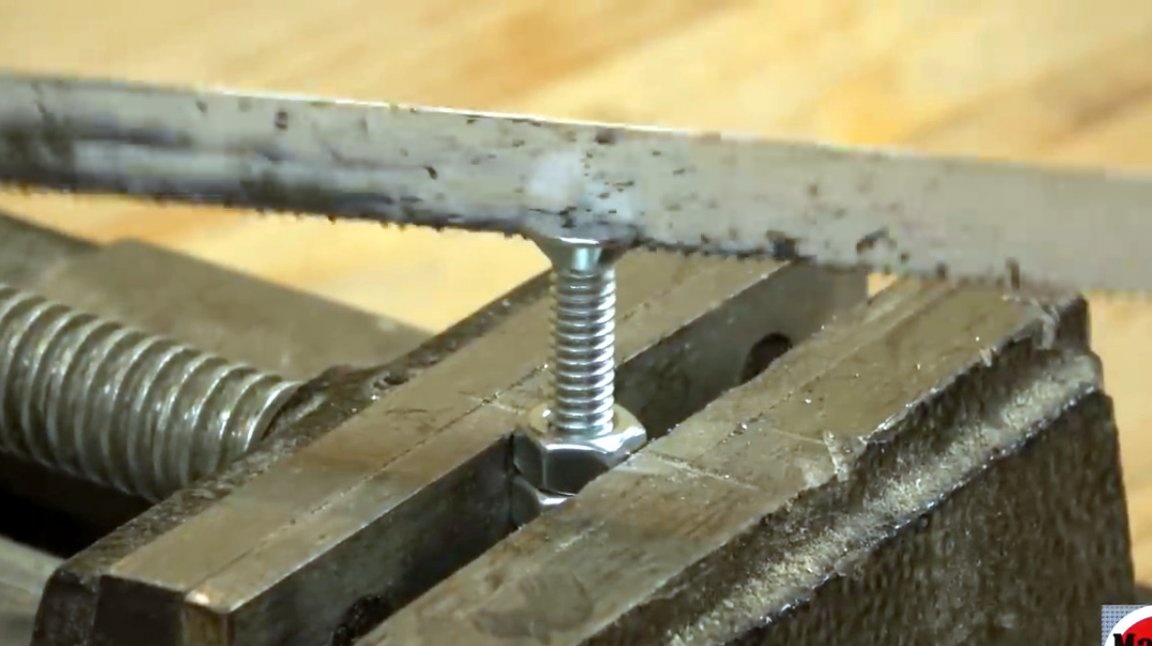
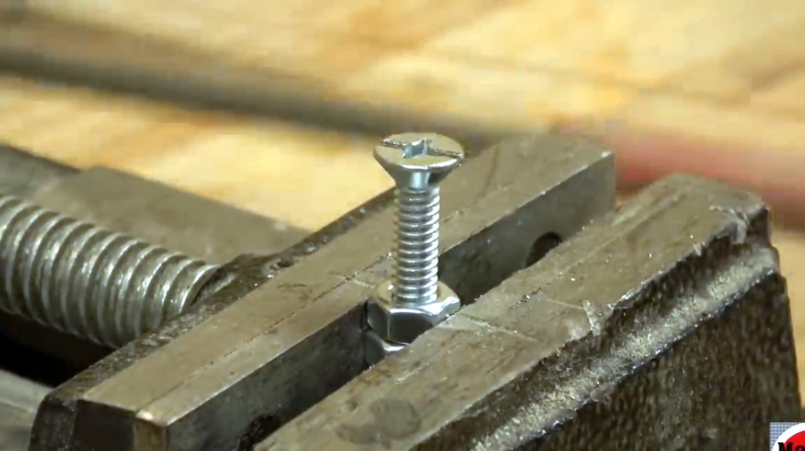
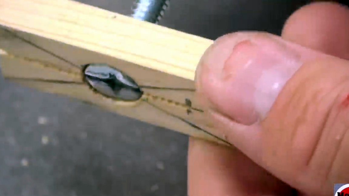
On a bolt that will be screwed into the locking block, the author makes notes for an incision. The bolt is clamped in a vice and sawn with a hacksaw.

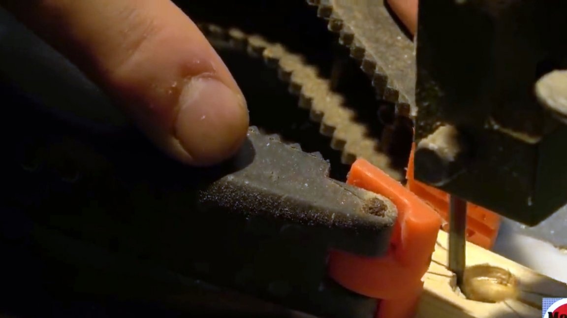
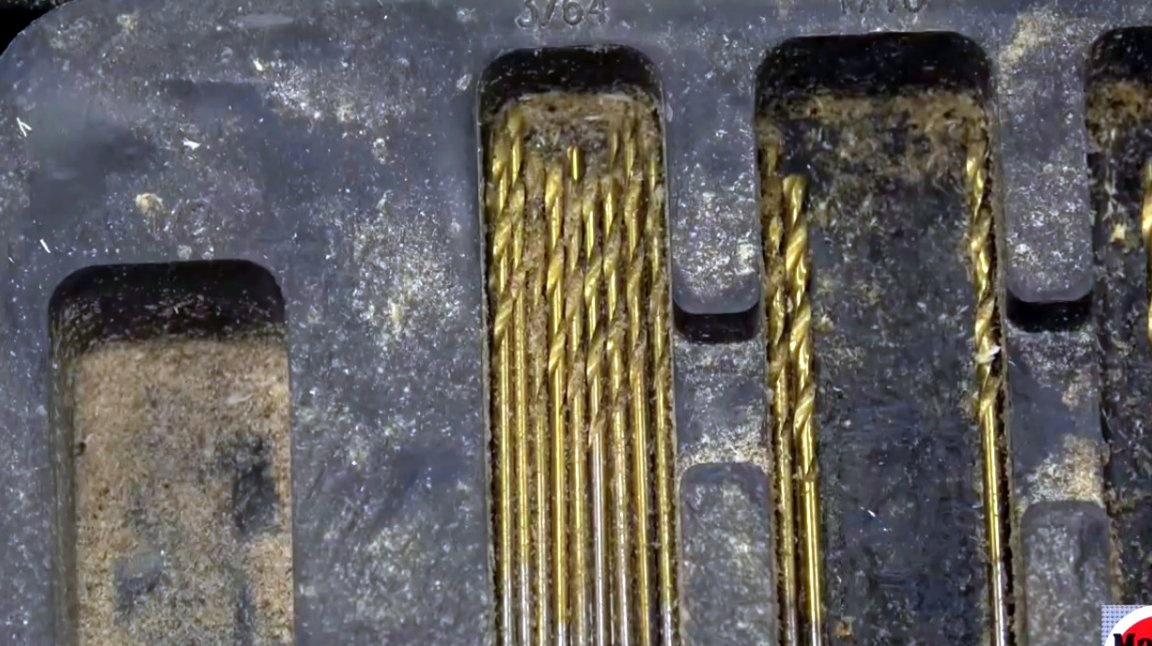
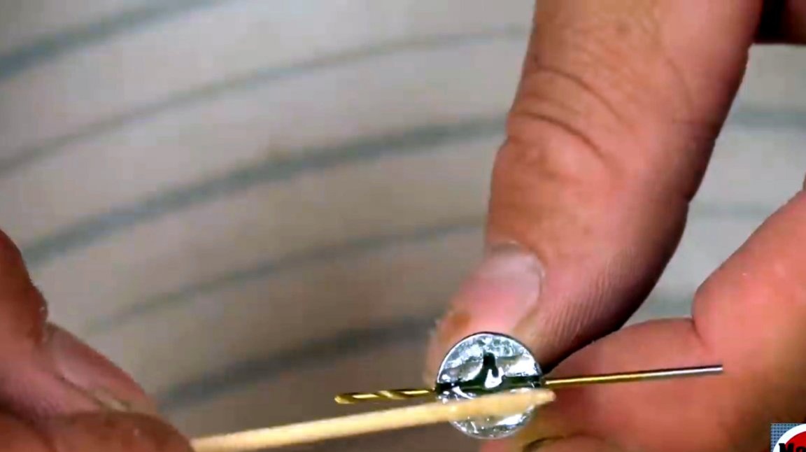
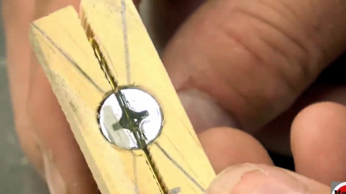
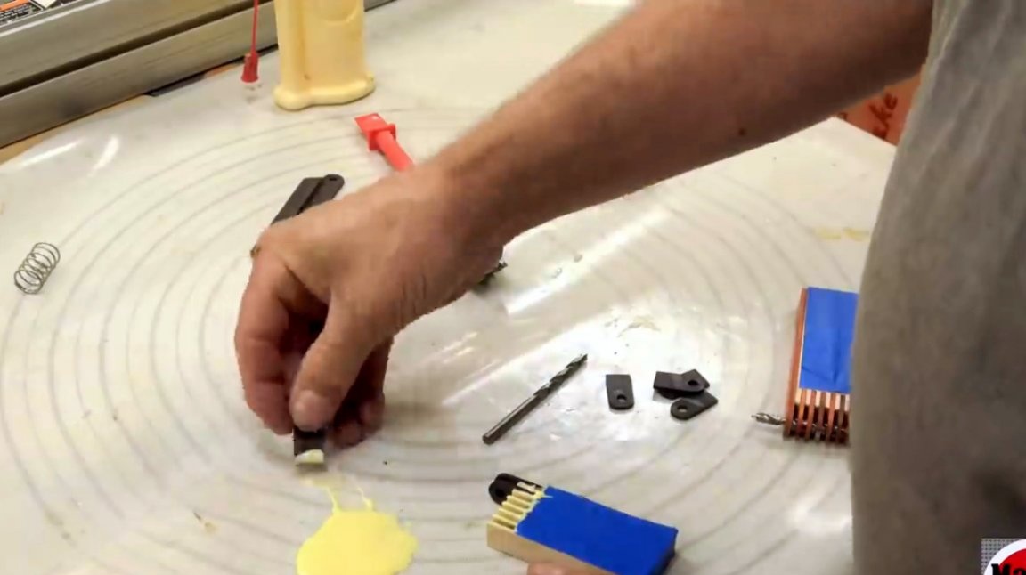
From his set of drills, the master chooses one 3/16 inch - this is just the right size. A drill placed inside the groove prevents the bolt from turning in the slot.
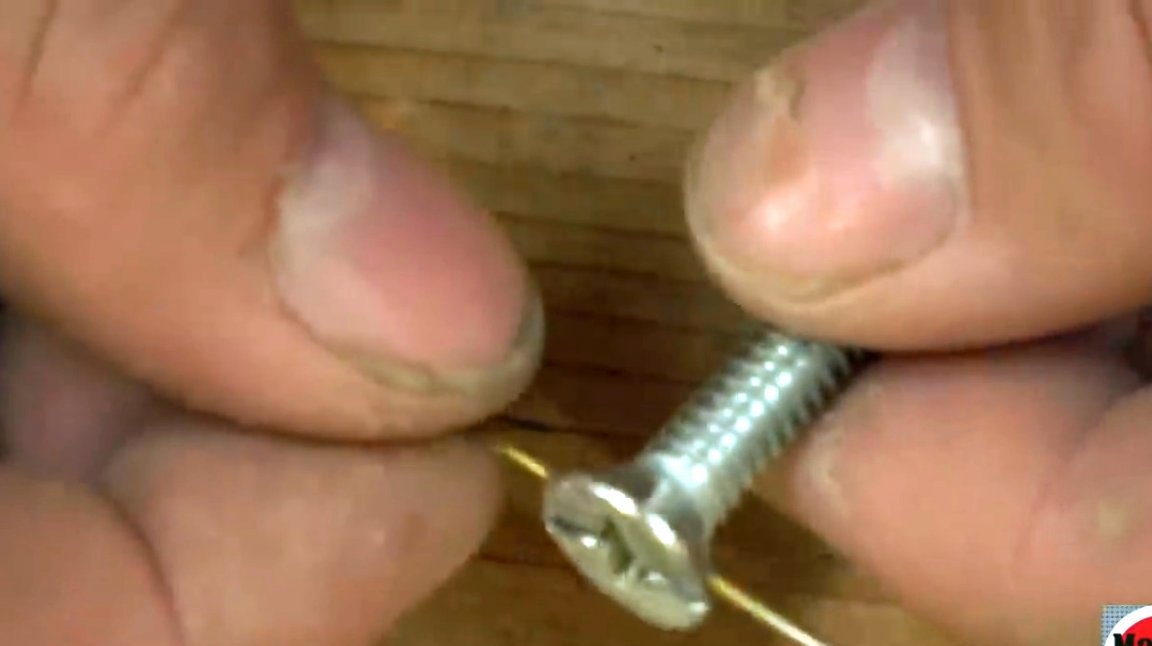
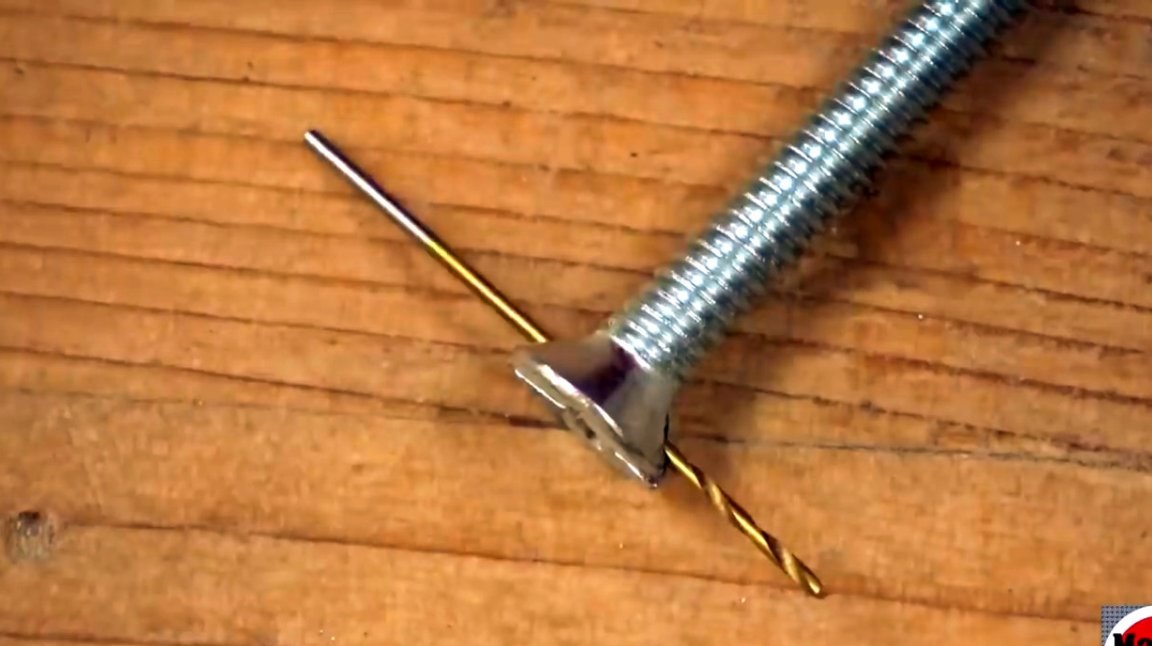
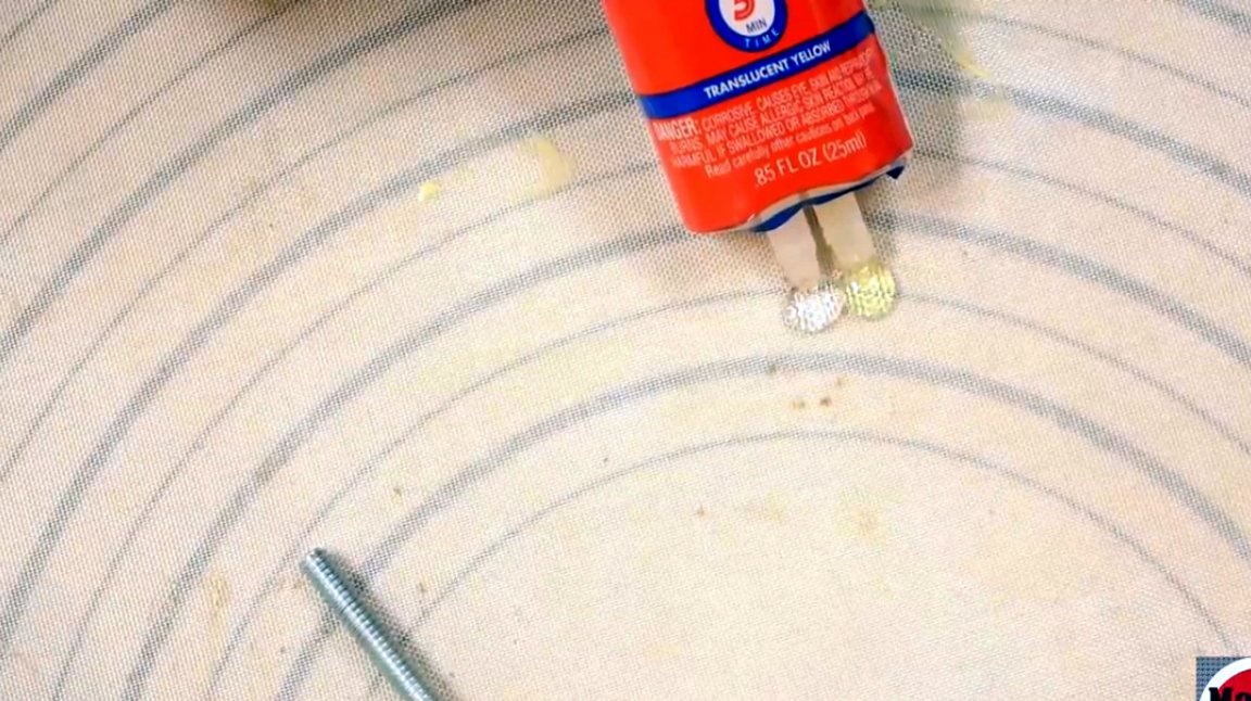
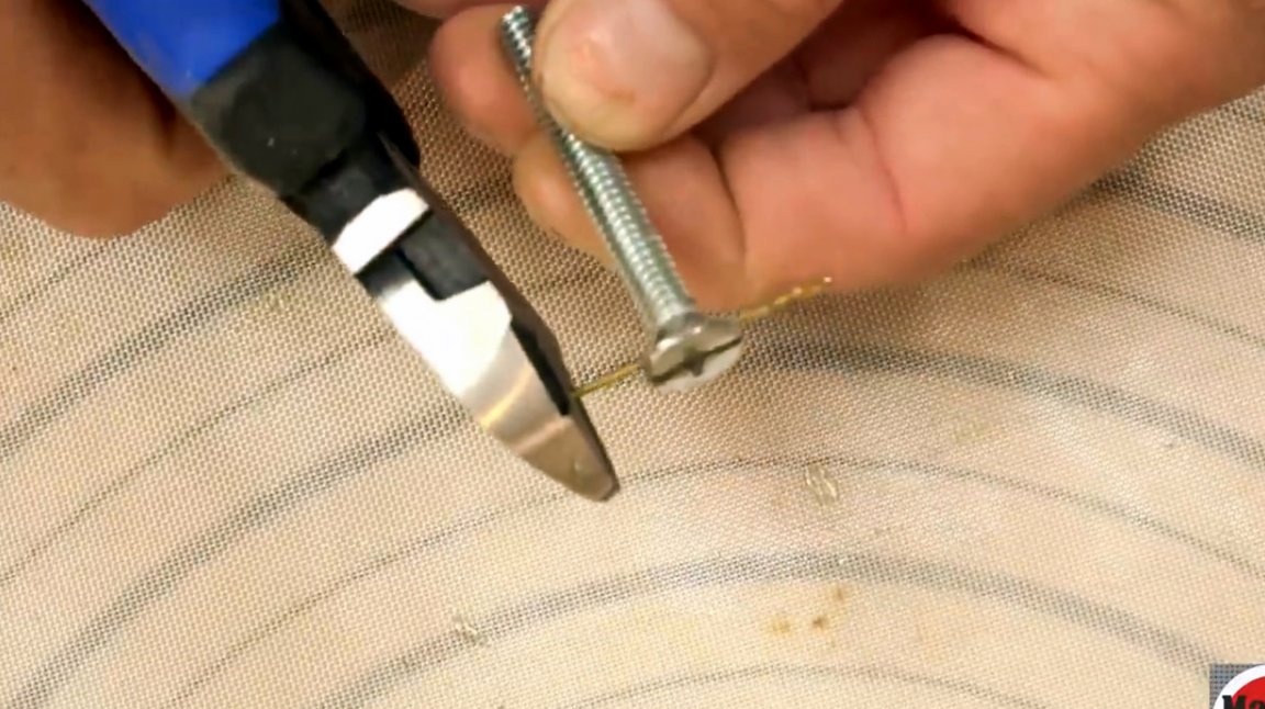
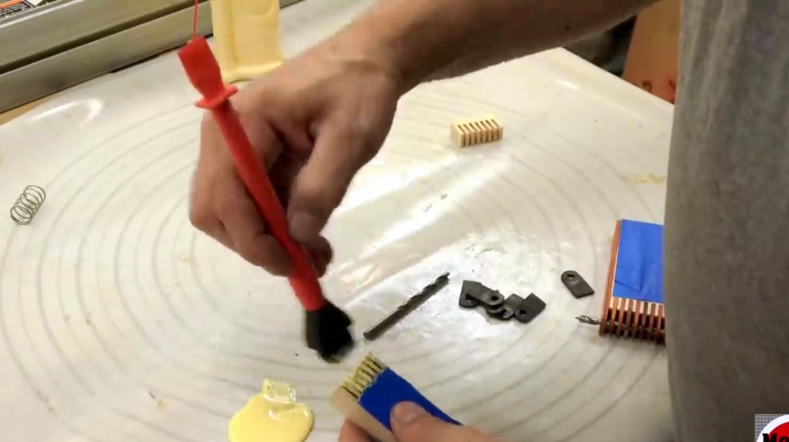
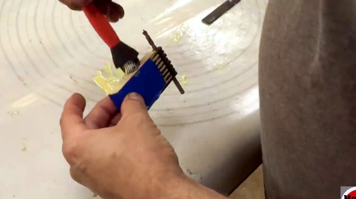
The drill is fixed in the groove with a quick setting epoxy. The excess parts of the rod bite off.
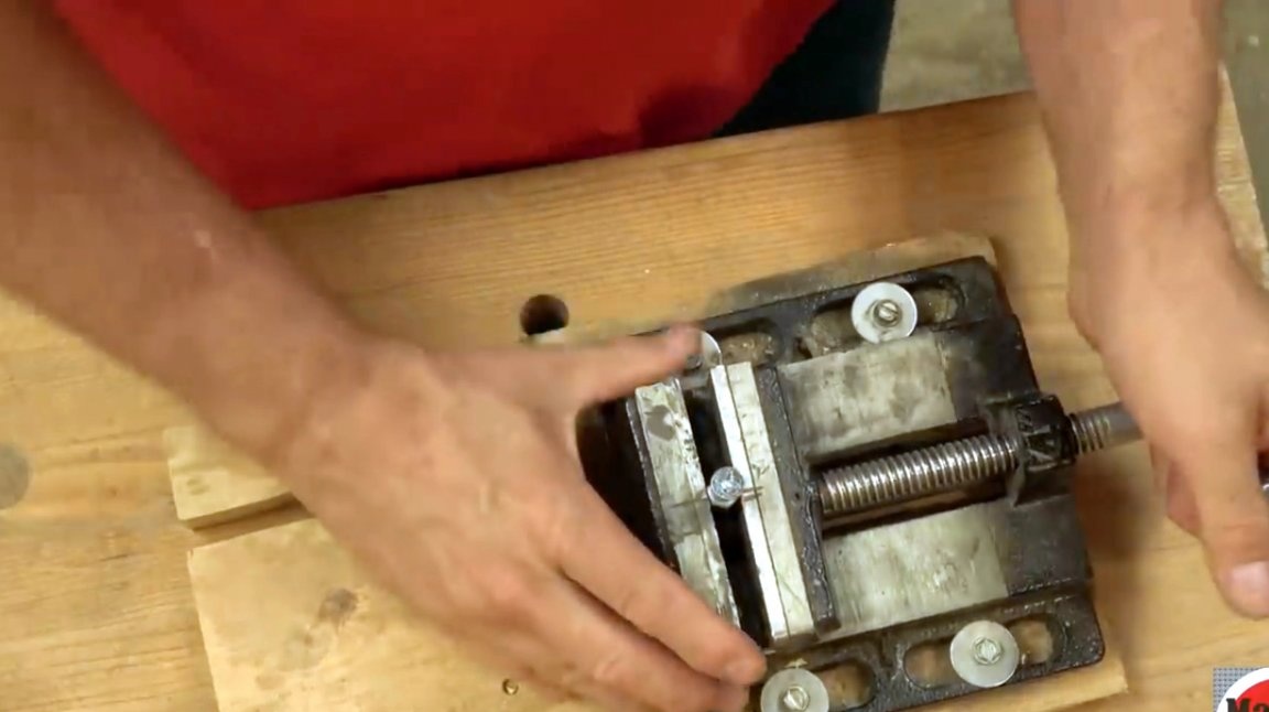
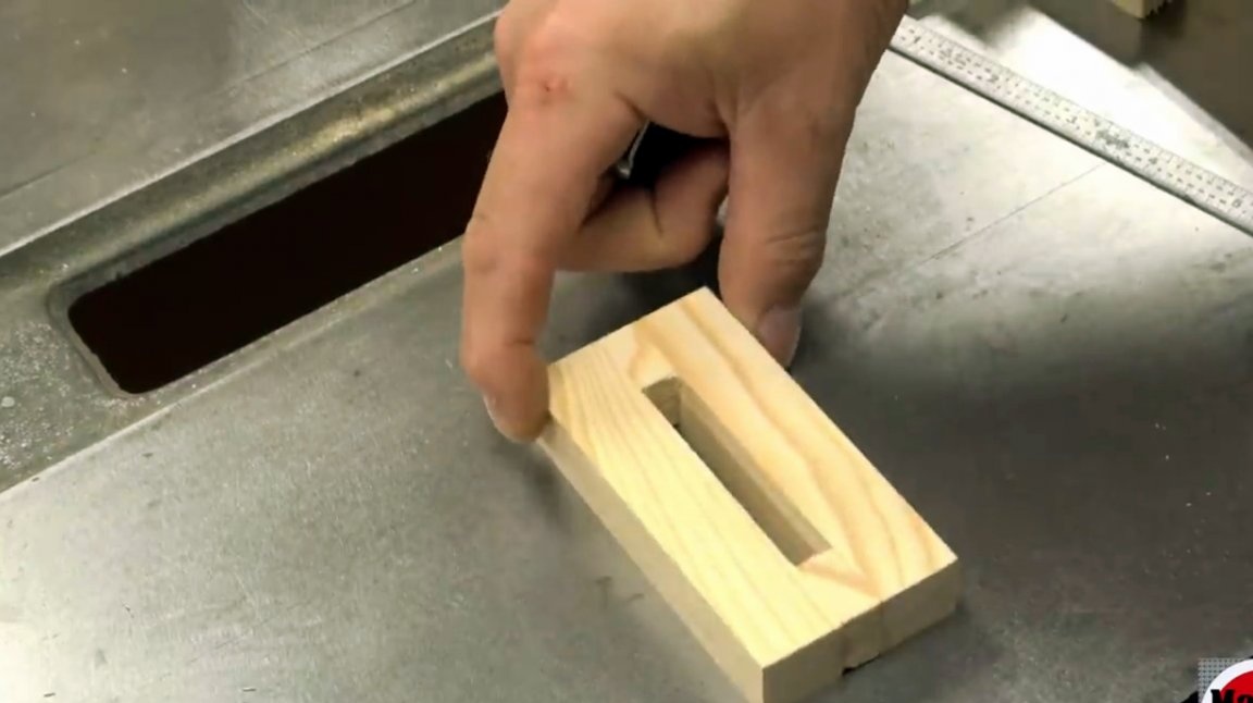
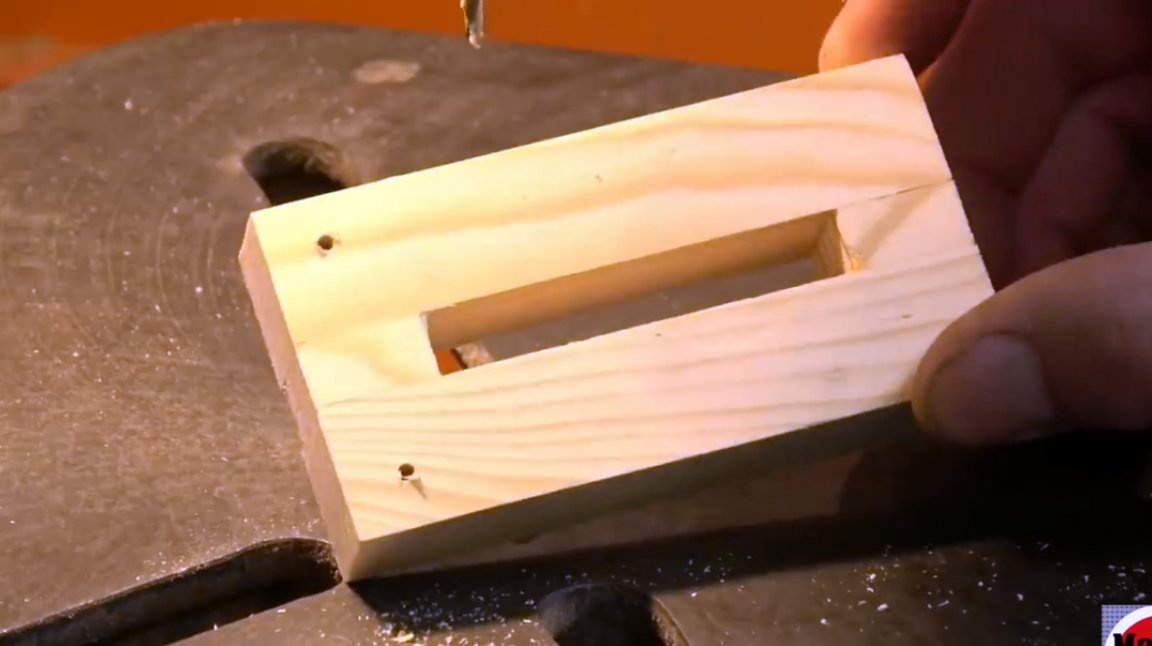
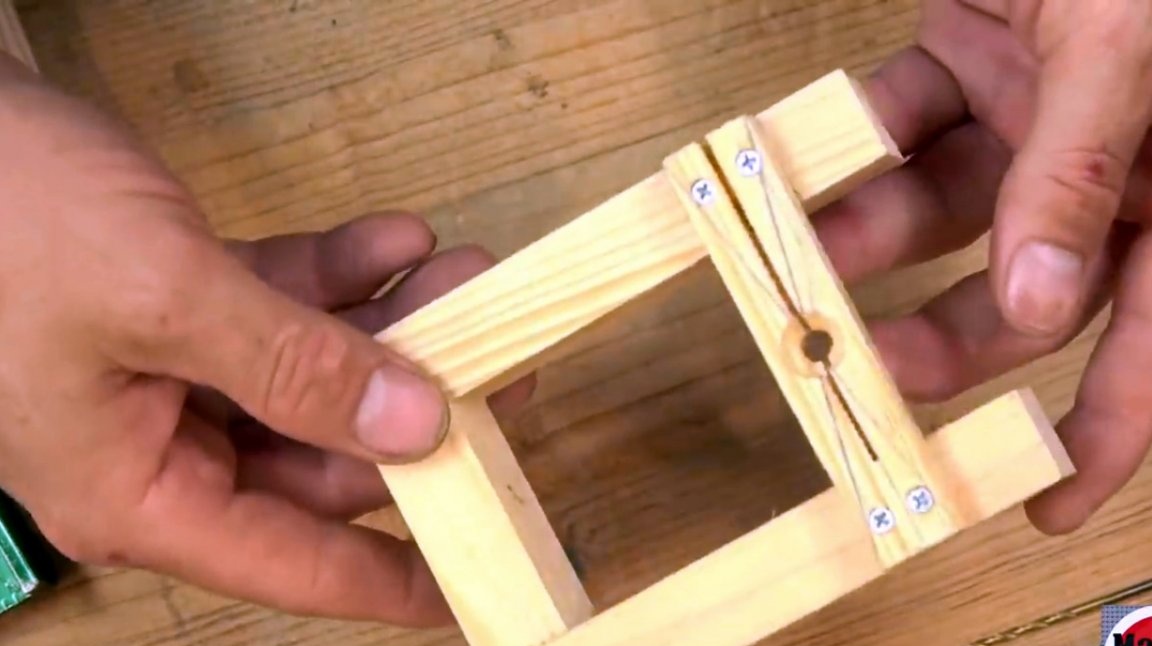
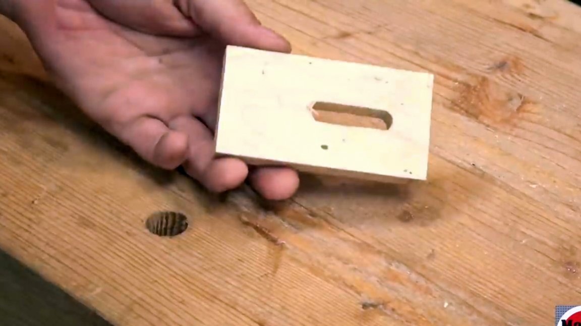
Now, on the transverse slide, the author makes the body of the device. He cuts a groove for a bolt.
Both sides will be 3 and 7/8 inches by ¾ inches. And the central parts will be approximately 3/8 inch wide.
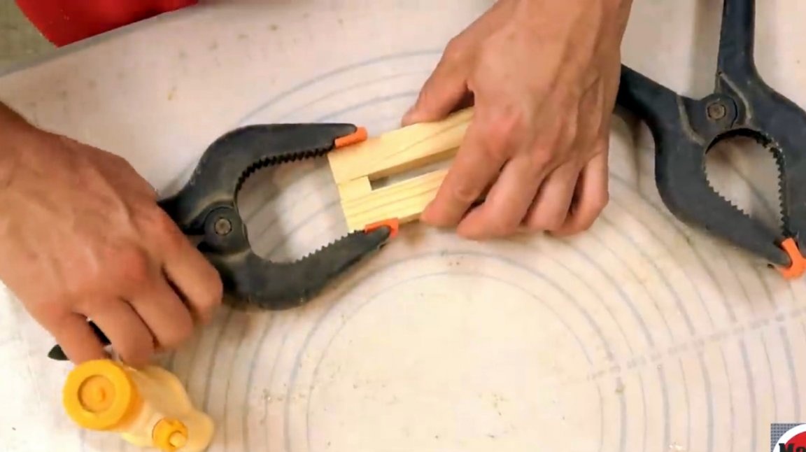
All elements are glued and clamped in clamps until completely dry.
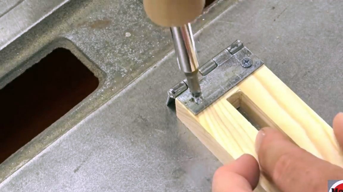
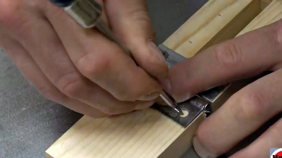
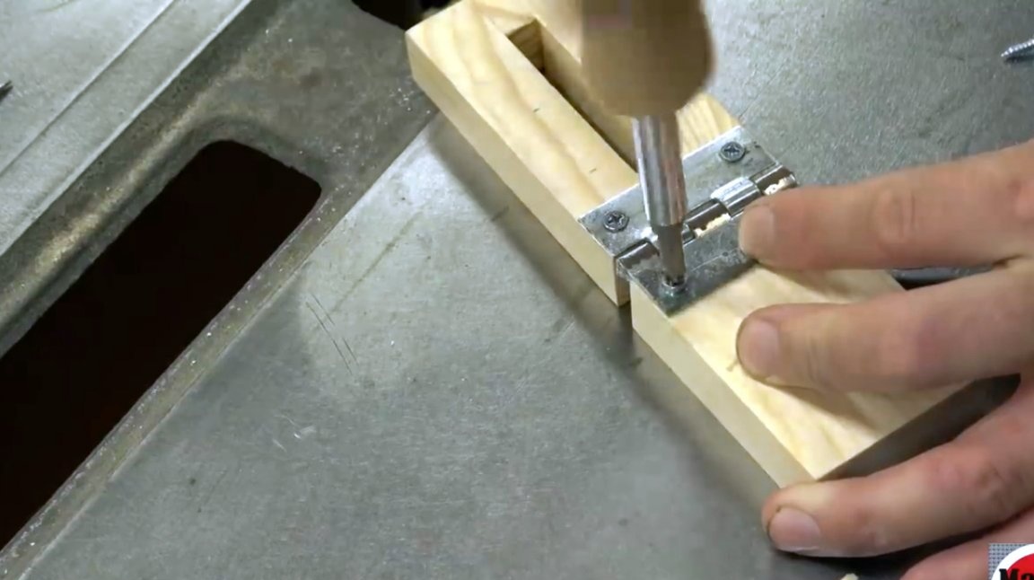
Then he marks the points under the holes for the loops with an awl. Then pilot holes are drilled.
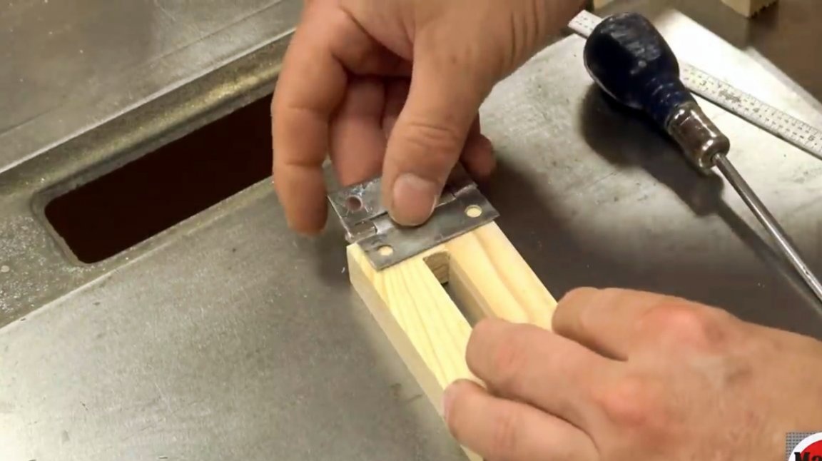
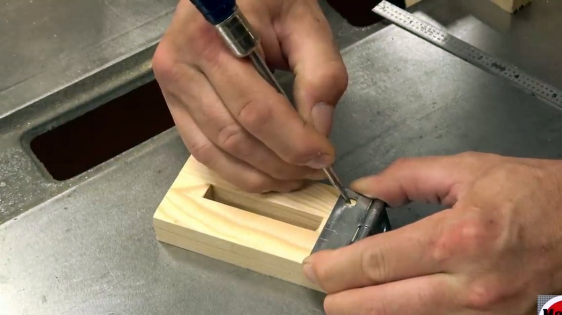
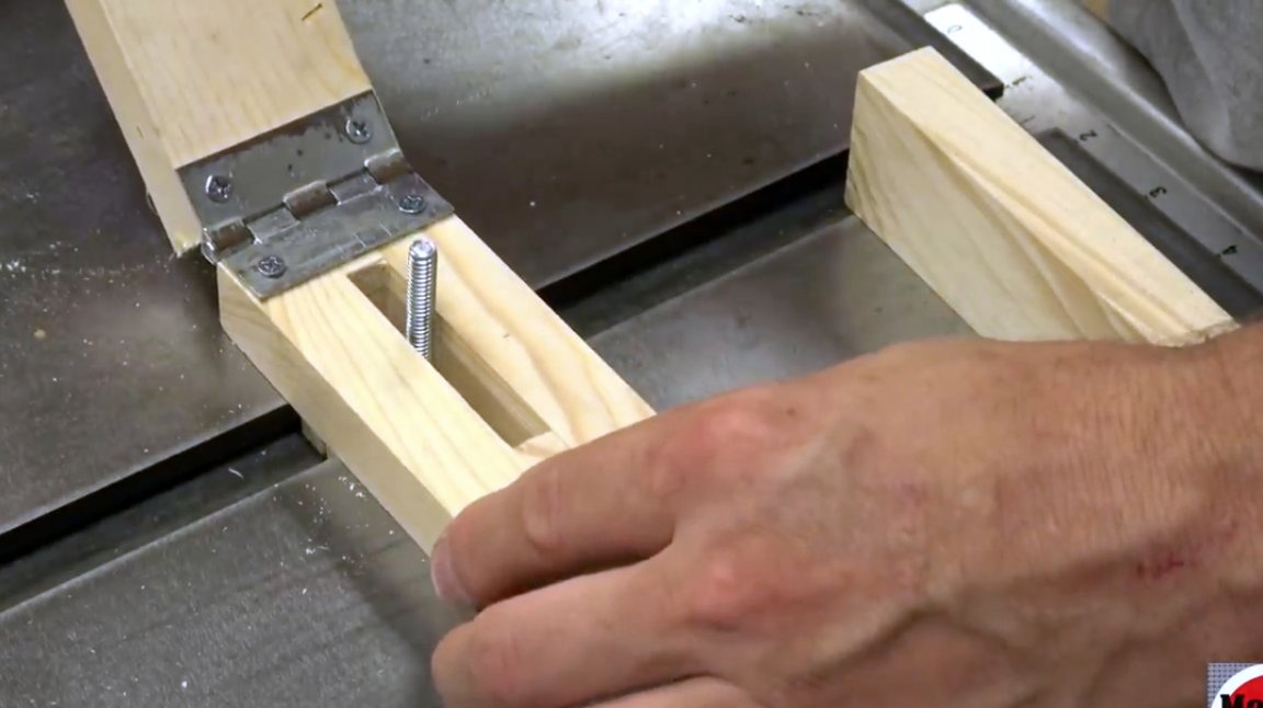
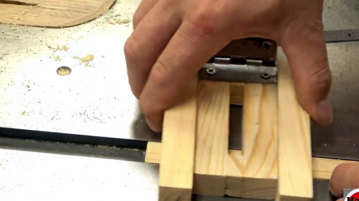
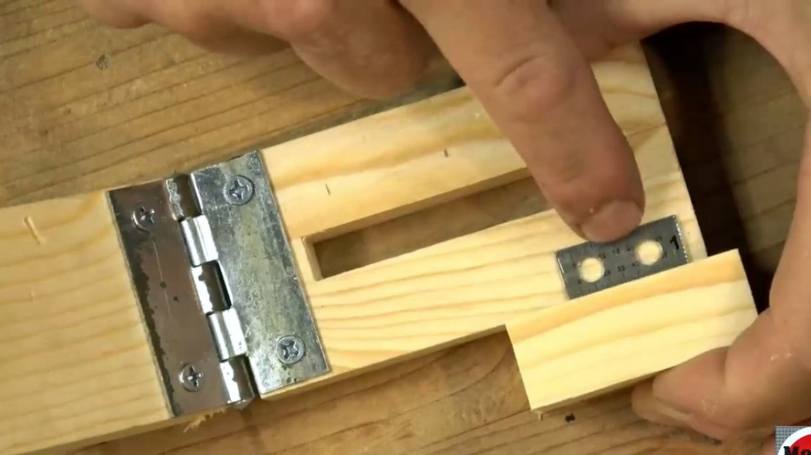
One half of the loop is screwed to the wooden case, while the other half will be attached to the mating part of the device.
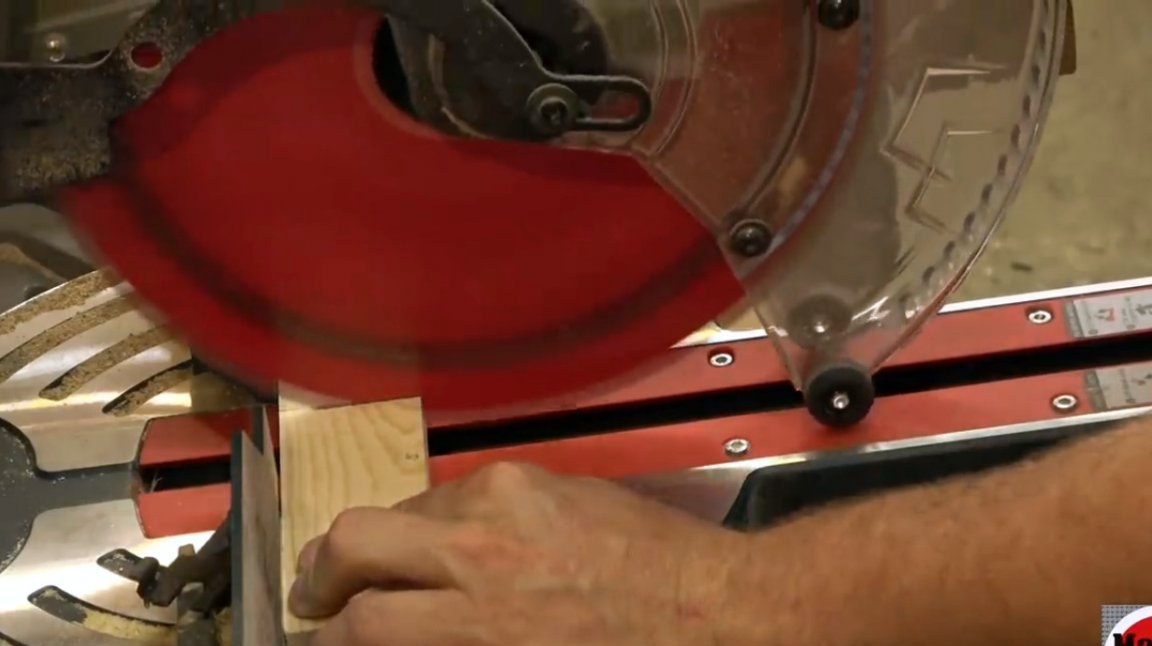
The author makes the necessary markings and cuts the part to size.
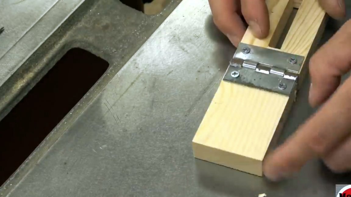
Then he makes pilot holes, and screws the second block to the counterpart of the loop. Now the device will be folded into the connection.
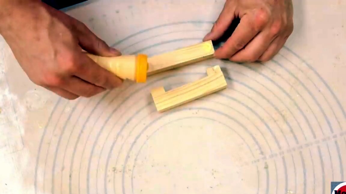
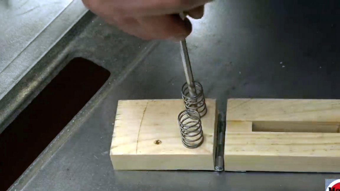
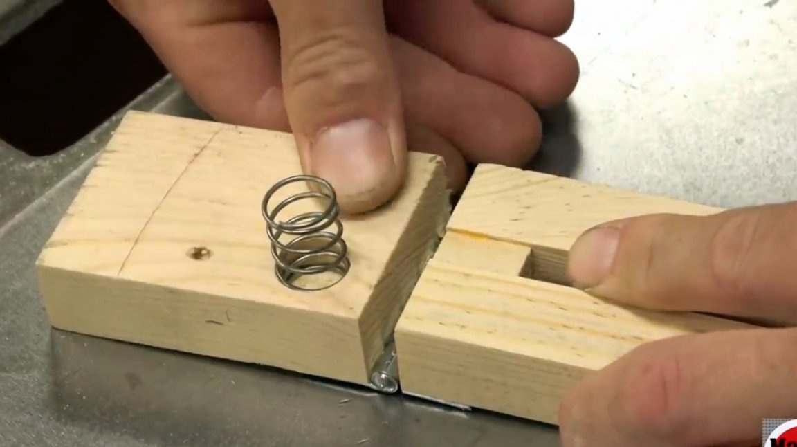
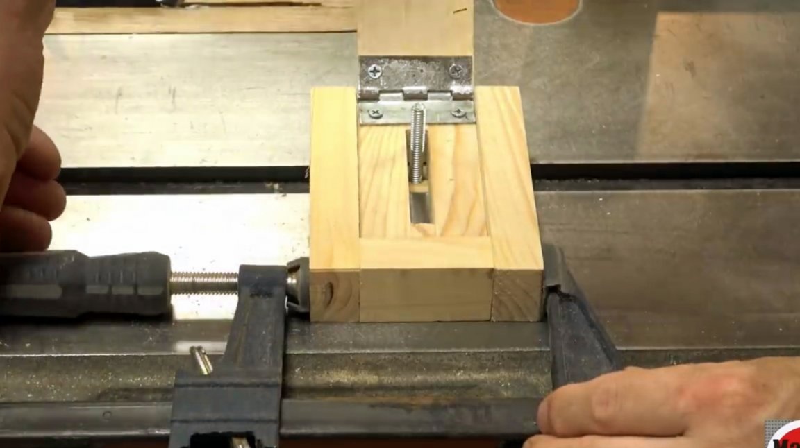
In order not to fold it manually each time, the master adjusts two springs with a diameter of 5/8 inches. Previously, two Forstner holes are drilled with a Forstner drill of the same diameter as the springs. Springs are mounted in them on an epoxy resin.
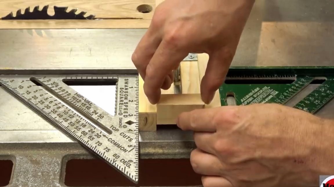
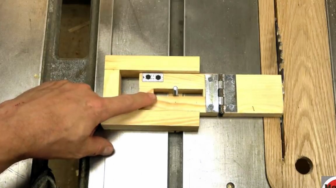
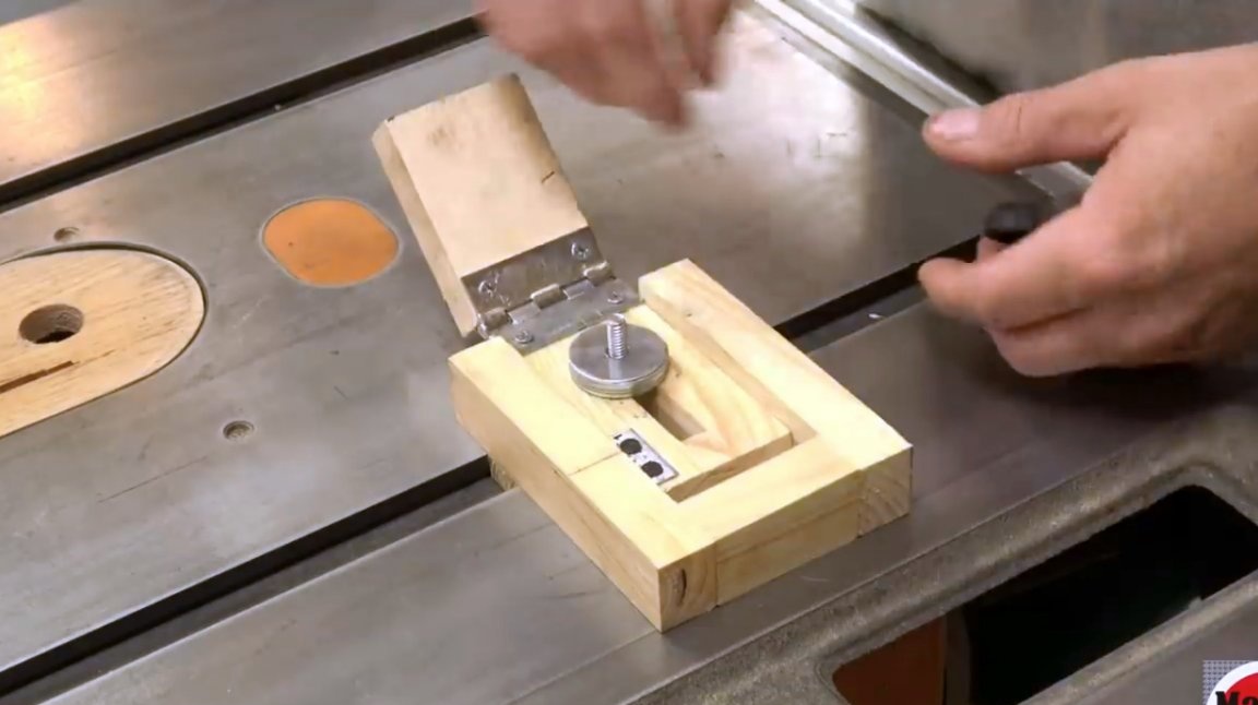
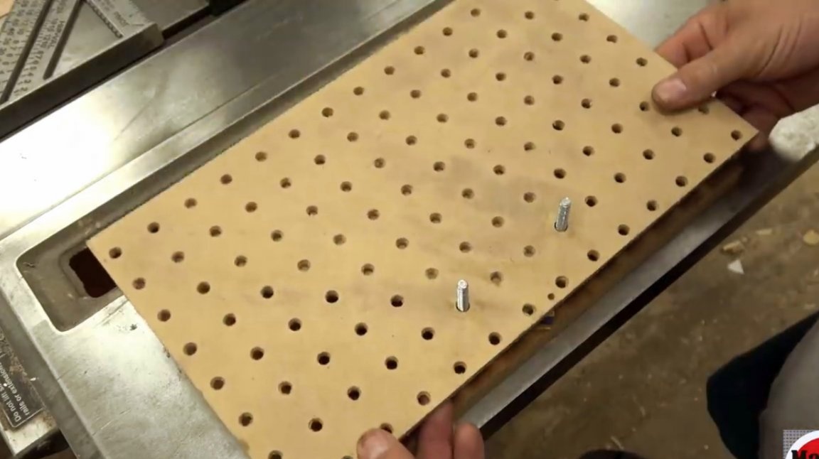
The bolt itself should be perpendicular to the P-track. Therefore, the author made just such a case.
In this project, the author had certain shortcomings and errors. However, his main goal was to give readers the idea of making such a device. It turned out to be the most difficult to fit all its elements to each other. Therefore, the second attempt, the master decides to simplify the design somewhat: he puts the guide bar under his device. Now this part is much longer, and occupies a significant part of the P-track.
Next, the master adds a pair of side walls, taking them to the glue, but not fastening them with clamps.
When the glue dried, the author added the last, third wall and also glued it. She clearly fit into the resulting gap.
However, glue alone is not enough, therefore, the author additionally screws screws into the bar, reliably attaching it to the base. So that the board does not crack, the master first makes pilot holes and countersinks them.
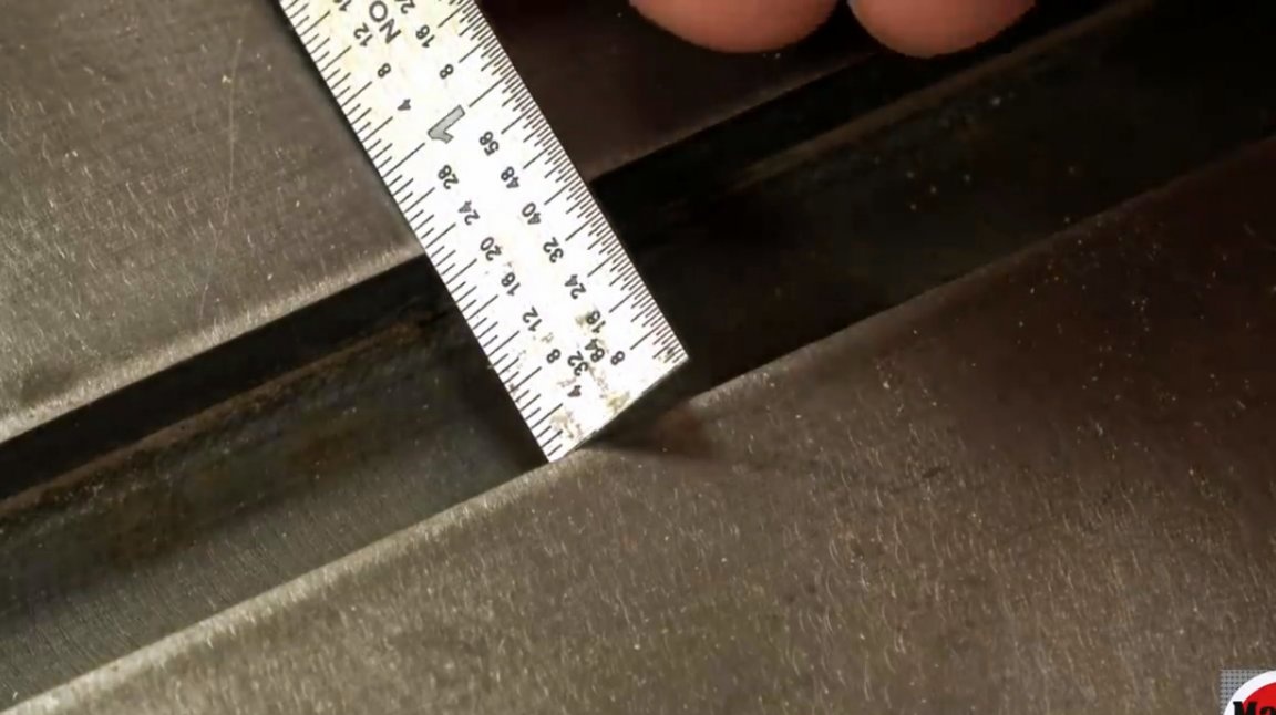
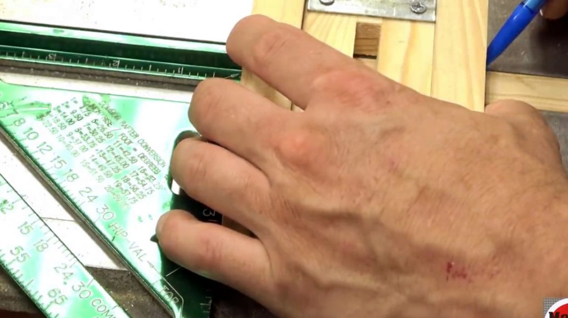
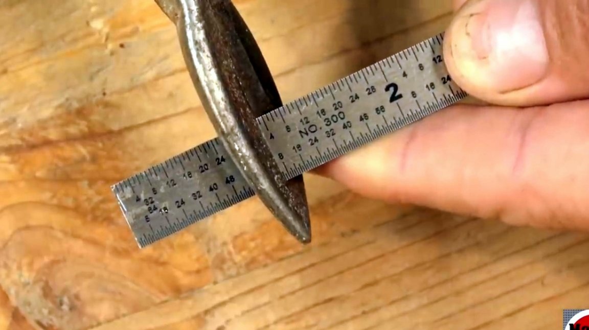
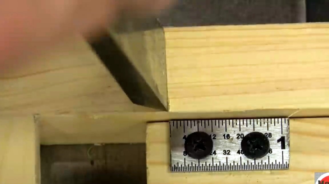
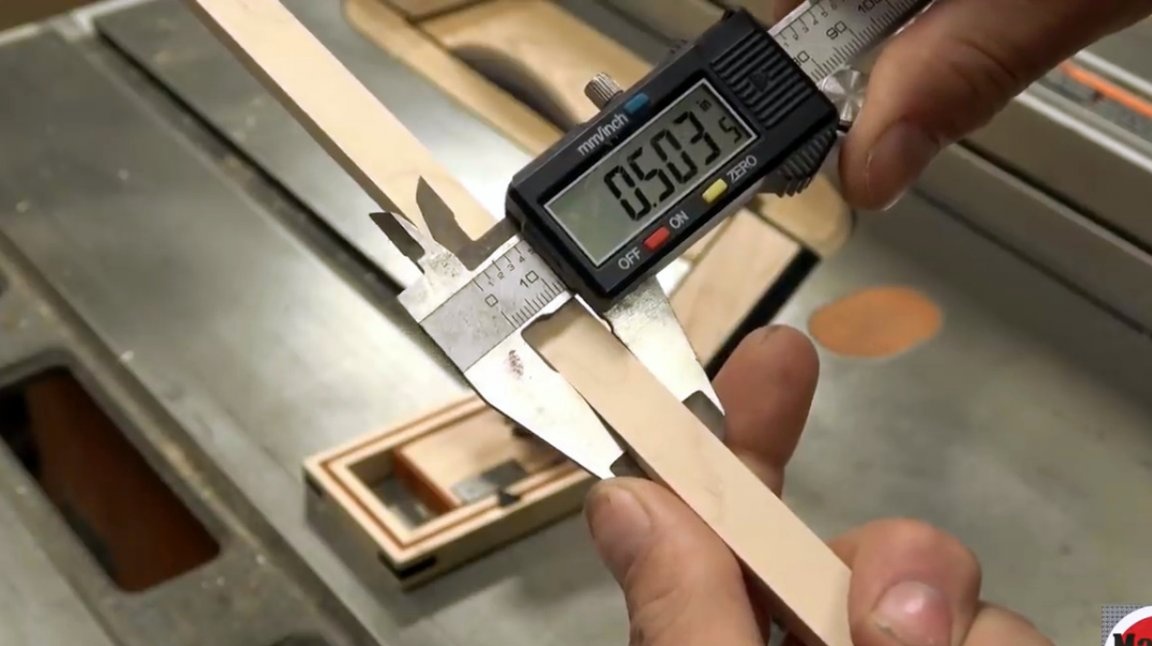
As a measuring device, the author uses a metal ruler, in which he bites off one of the sides to a mark of 1.8 inches. This will be its maximum length.
He clamps a piece of the ruler in a vice and drills two holes for screws in it.
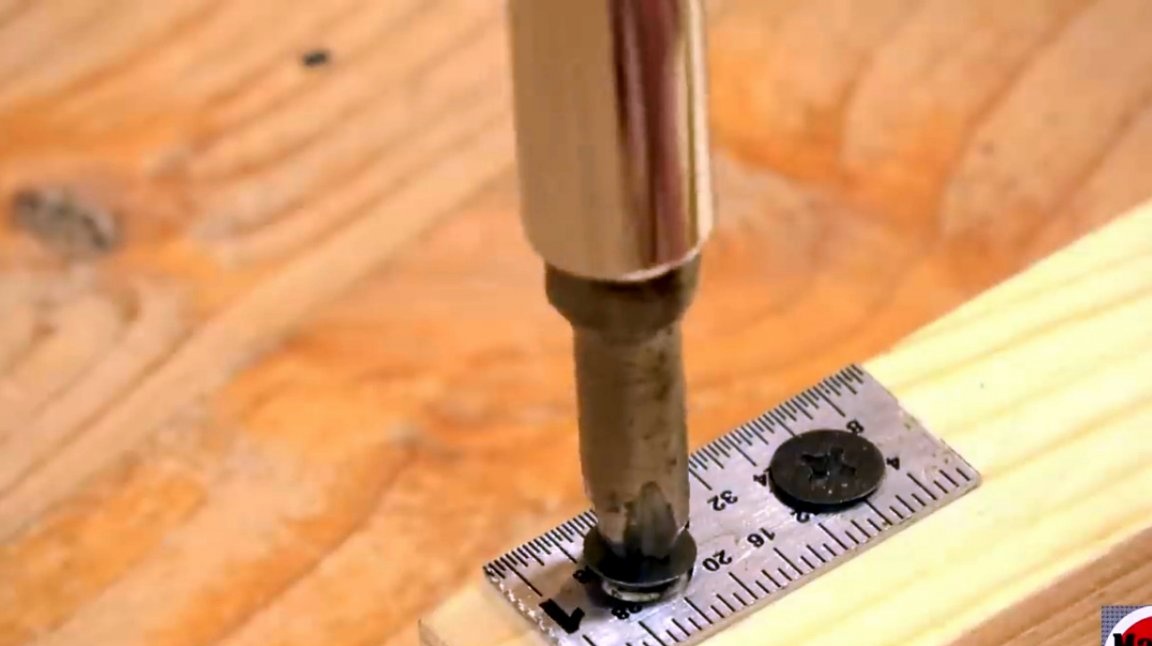
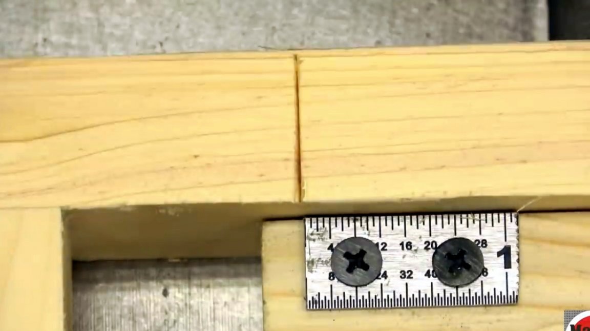
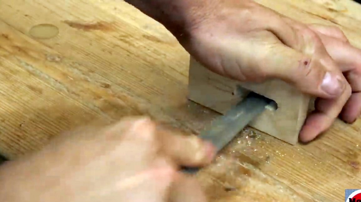
This is how the master sets the absolute zero to the blade of the saw blade before transferring the same mark to his fixture with an ordinary chisel and fixes it on the case with self-tapping screws.
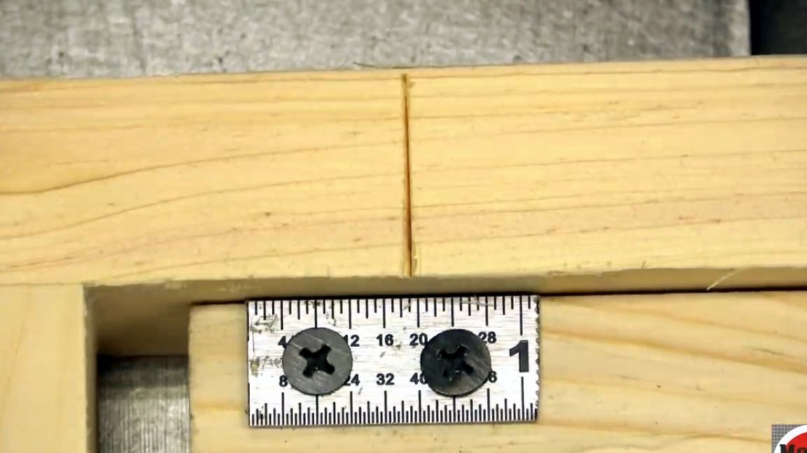
Since the walls of the structure turned out to be slightly higher than the inside of the fixture, the author uses a washer before screwing a plastic wing nut.
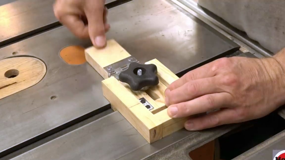
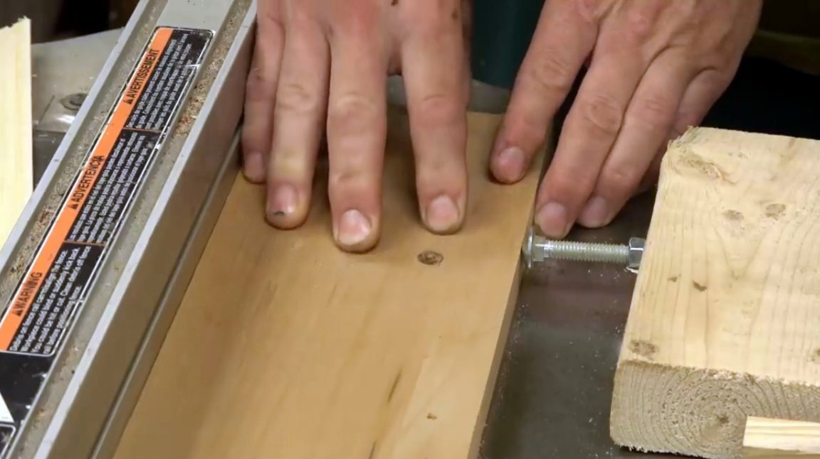
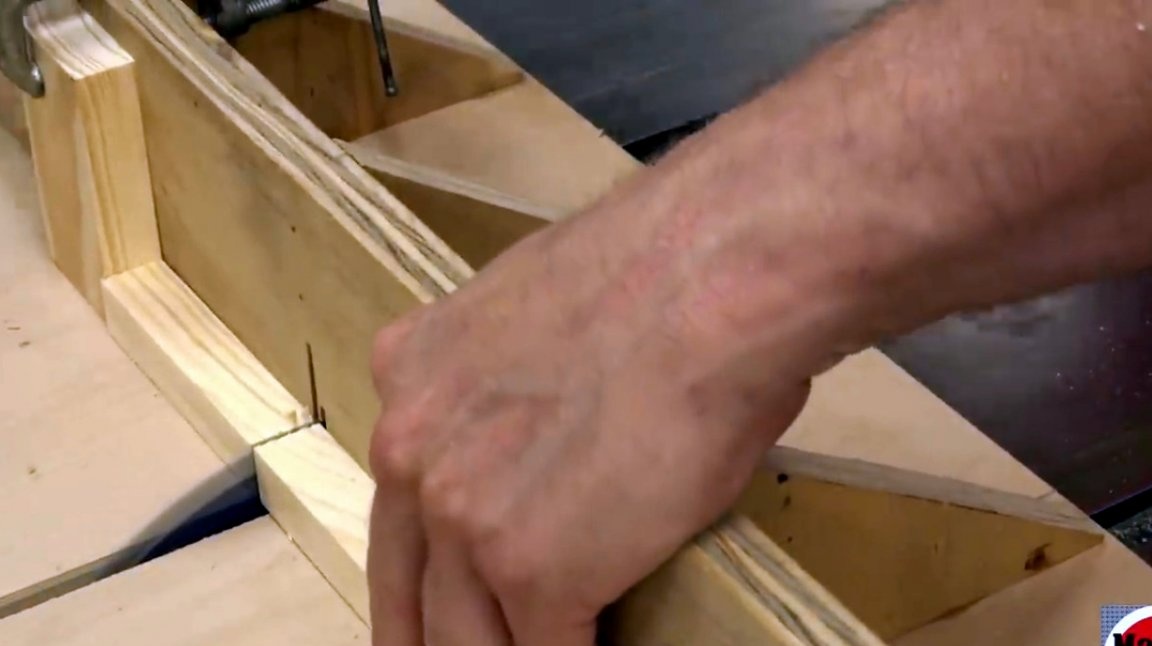
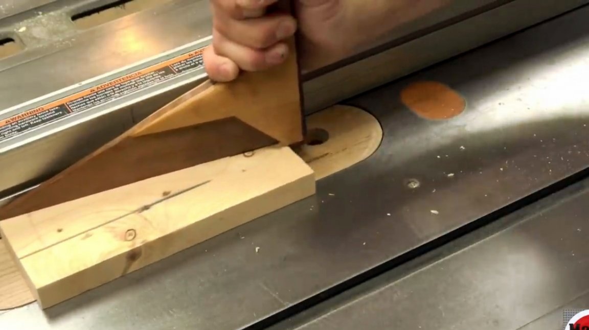
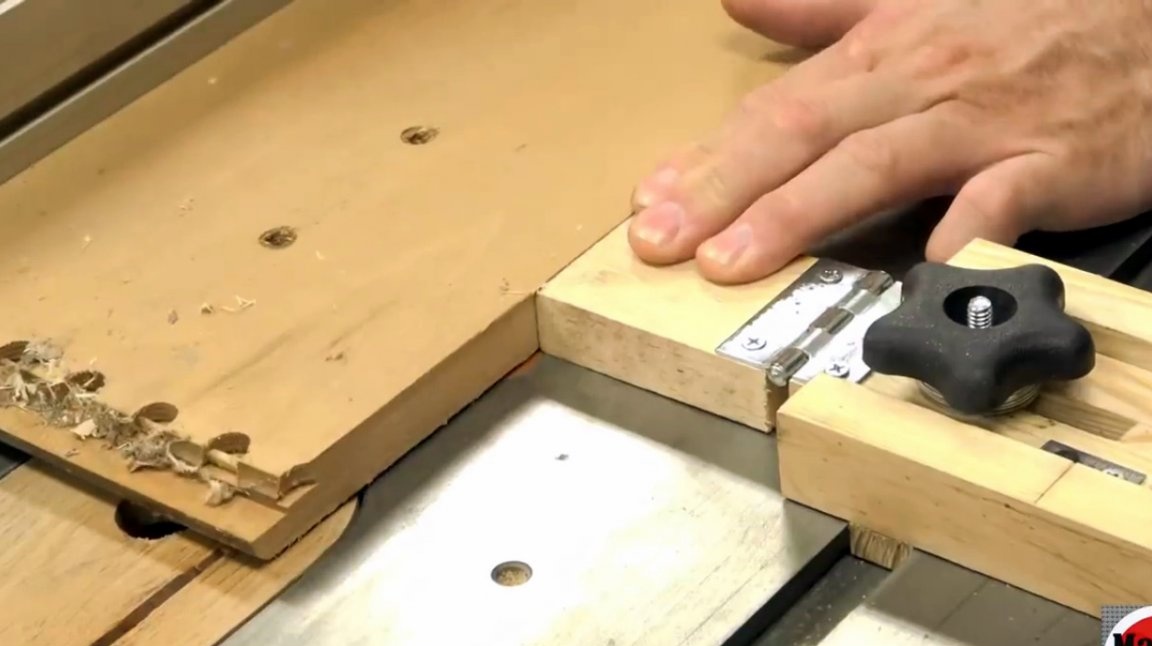
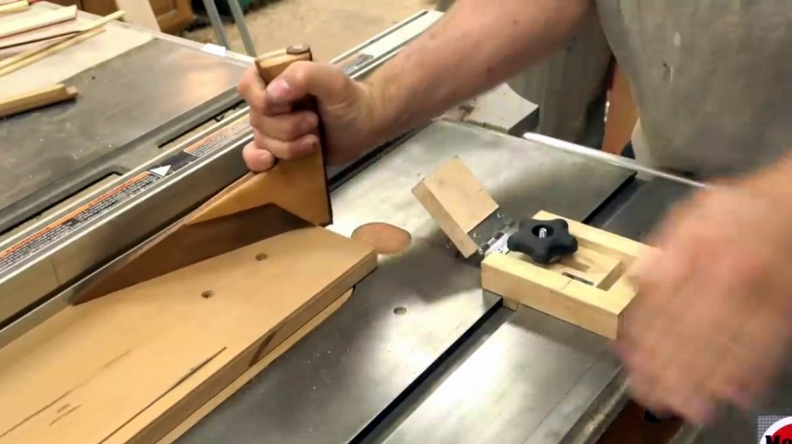
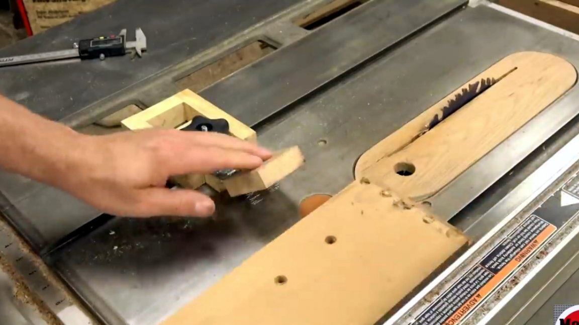
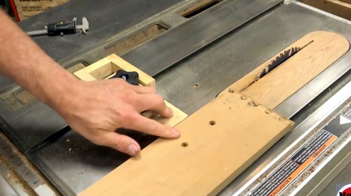
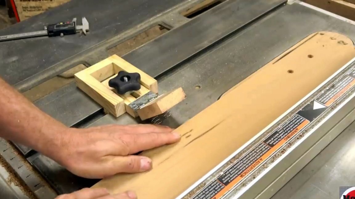
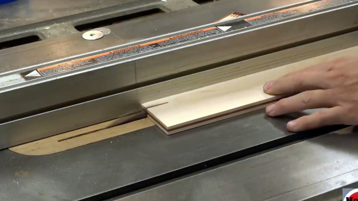
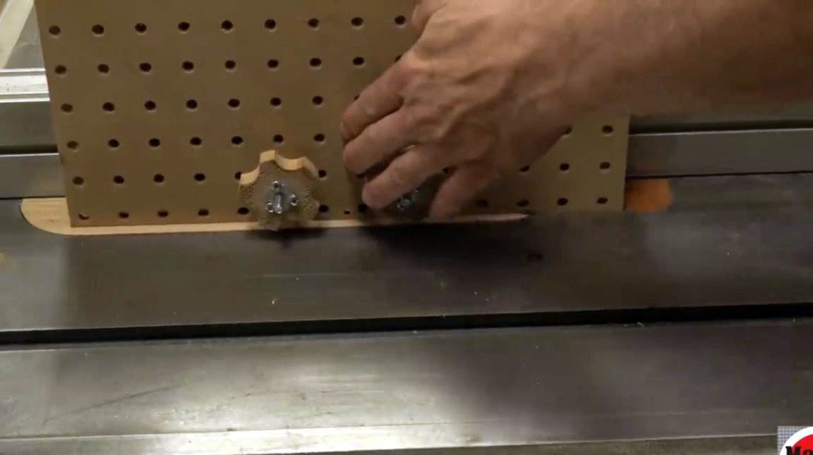
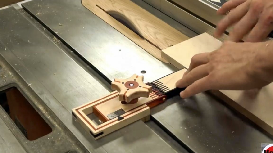
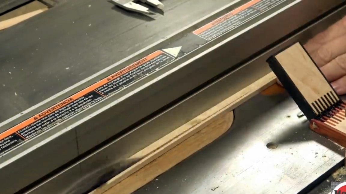
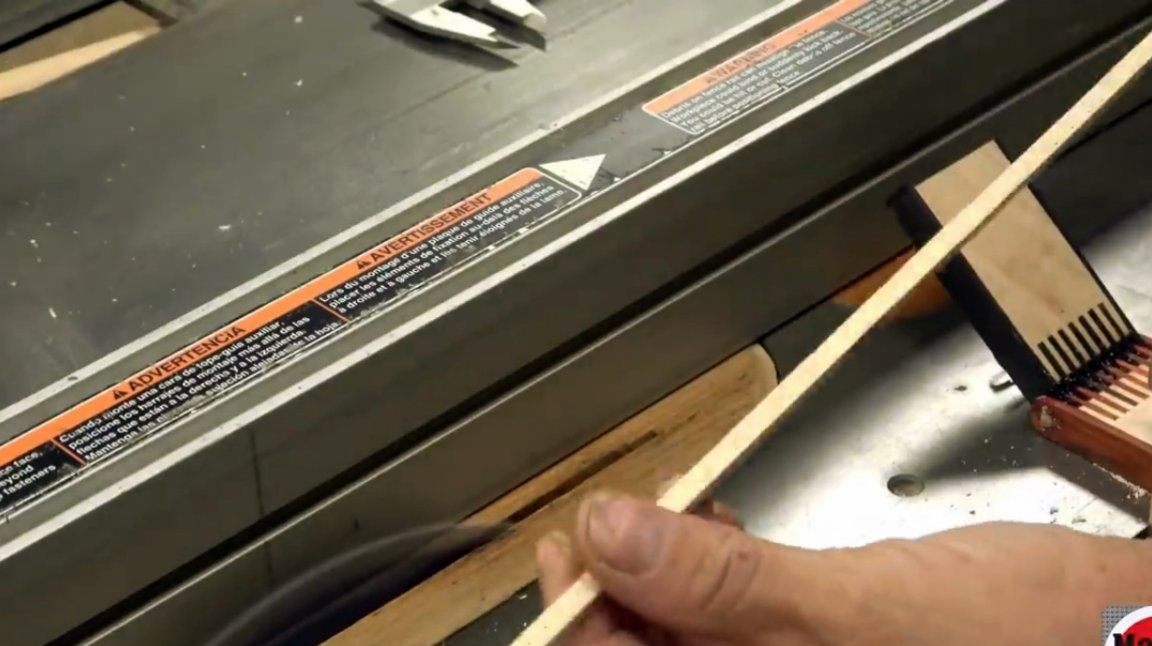
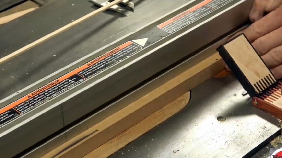
When using this device, the board is pressed against the edge. Now all that remains is to fix the emphasis and begin to cut the board into thin plates.
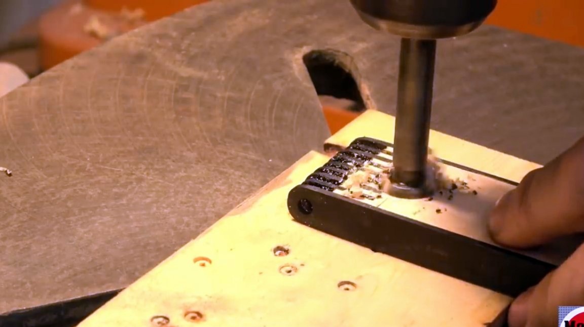
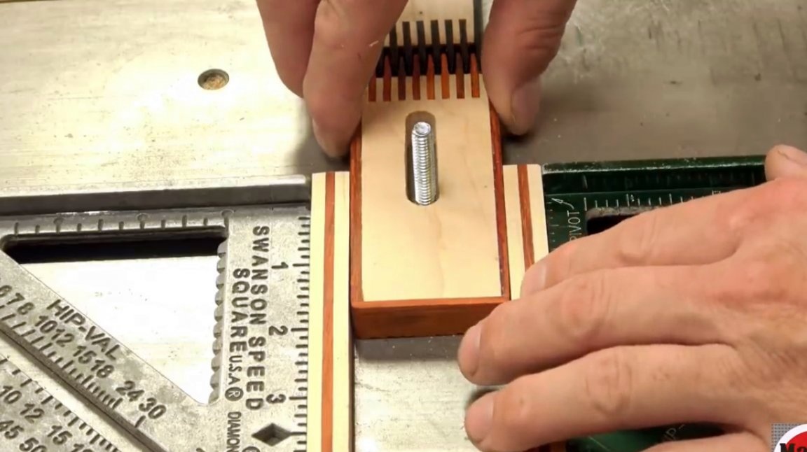
But the author does not stop on this model, but decides to improve it somewhat. It leaves the case unchanged, but brings some modifications. In particular, now he is drilling a connector for a bolt and scraping its edges with a rasp.
He replaces the metal loop with a swivel joint. He makes such teeth with holes at the ends through which the axis must pass.
In addition, he reduced the thickness of the case and received a profile of much smaller sizes.
Instead of two springs, he installs one. It does not distort the lift plate.
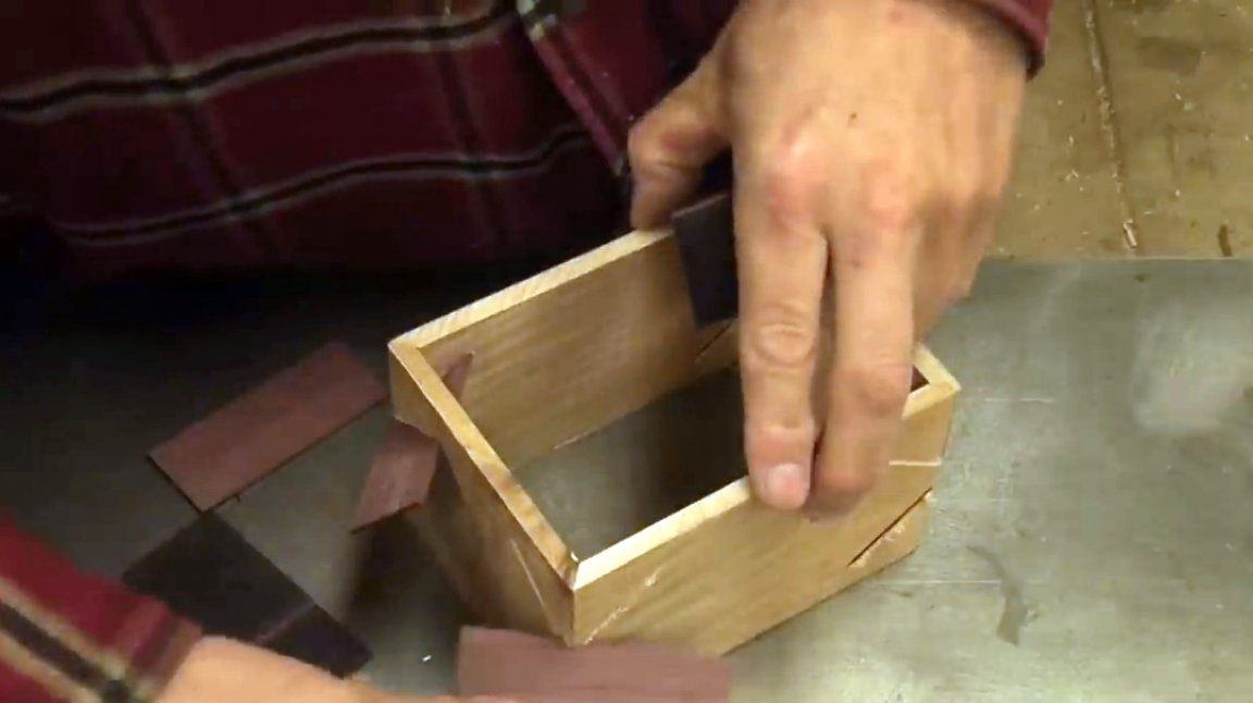
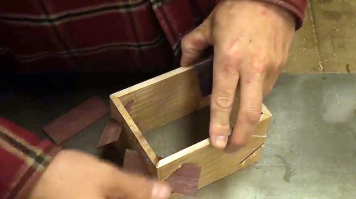
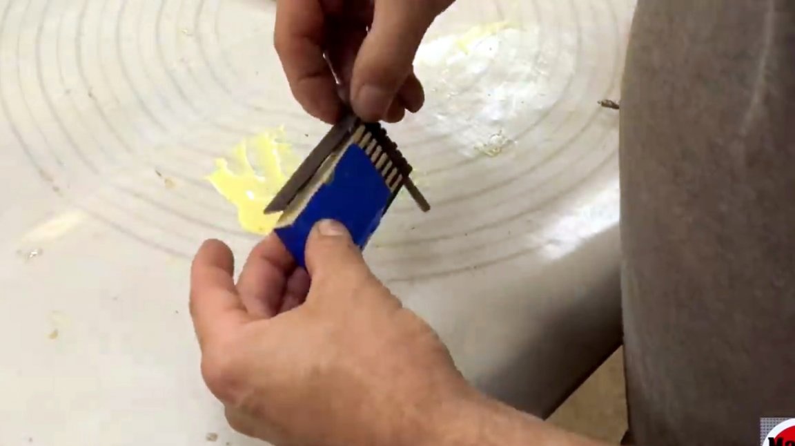
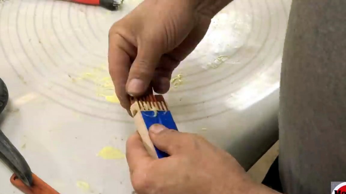
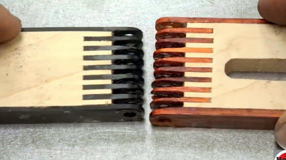
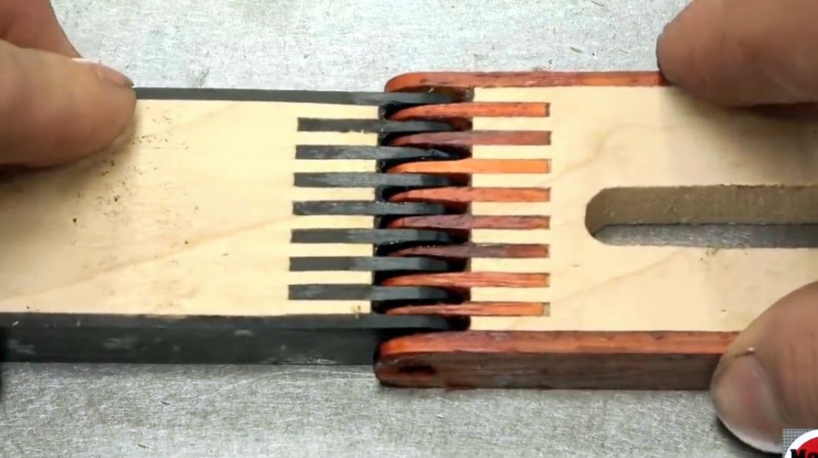
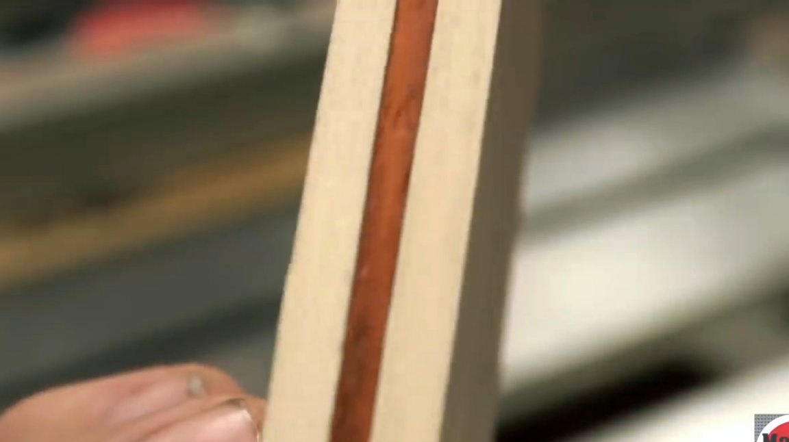
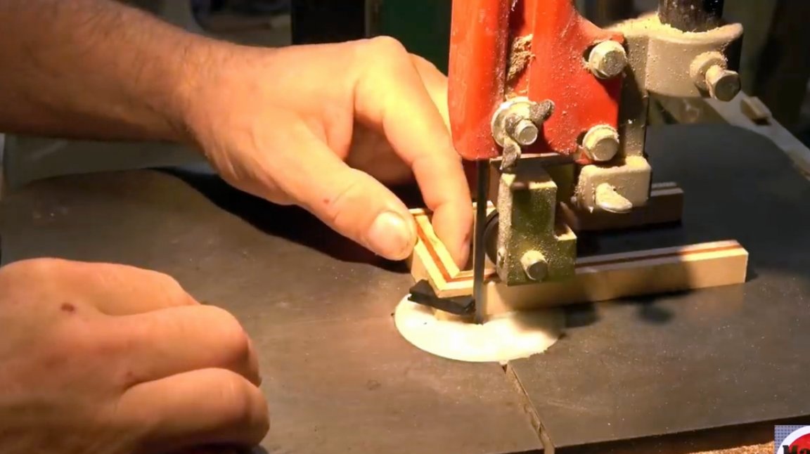
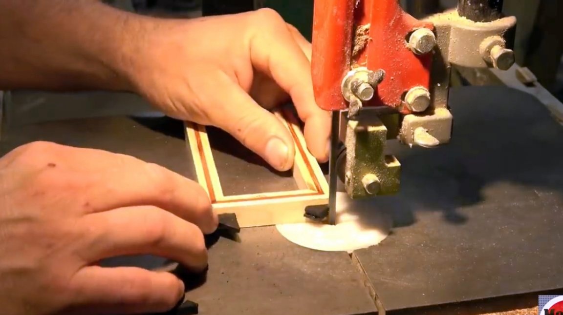
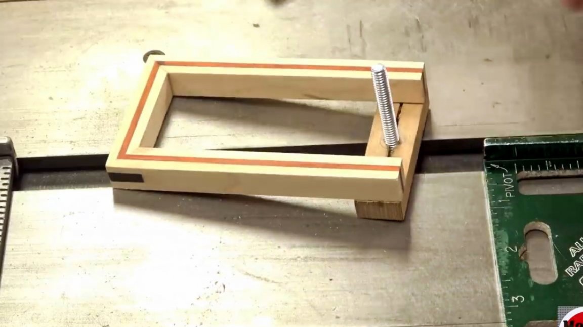
The master makes the box itself from combined wood, in which layers of maple wood are interspersed with layers of mahogany.
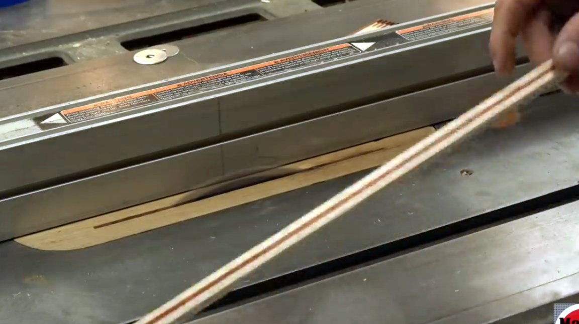
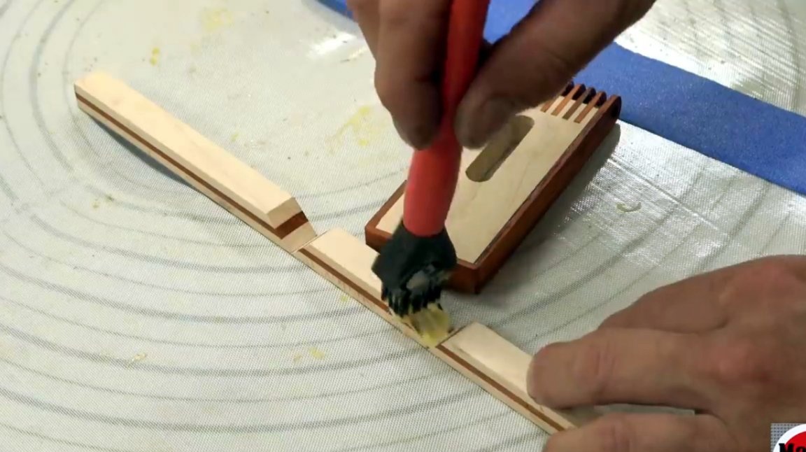
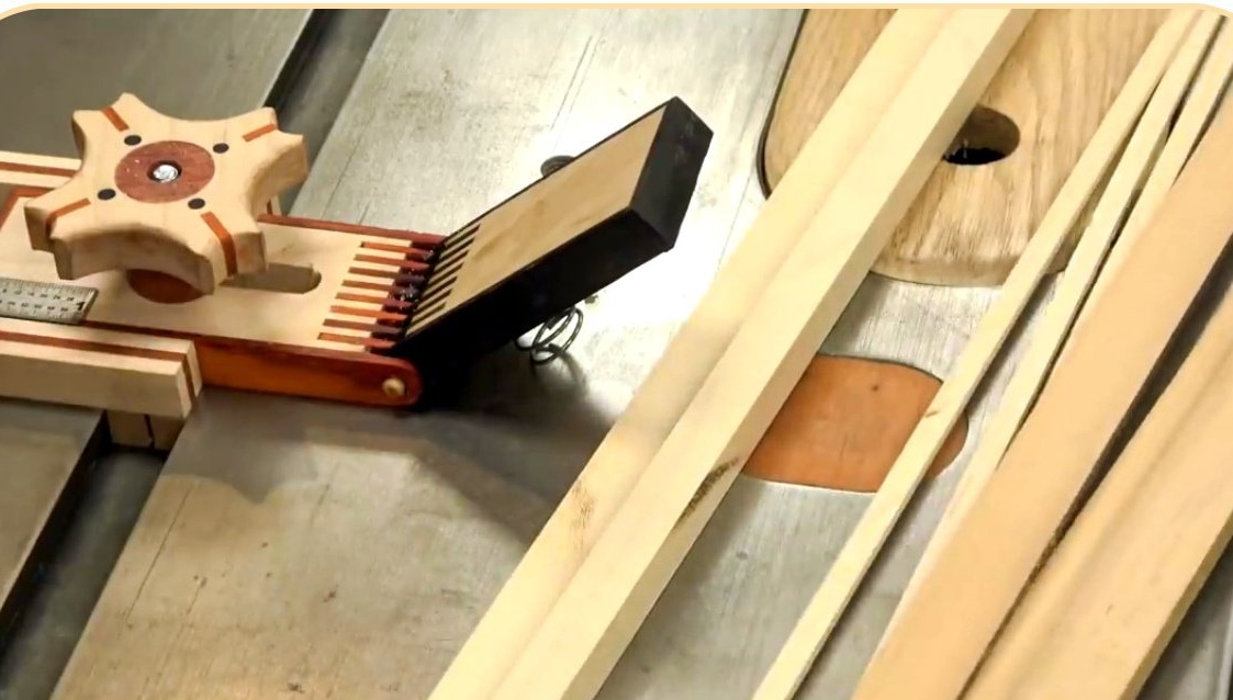
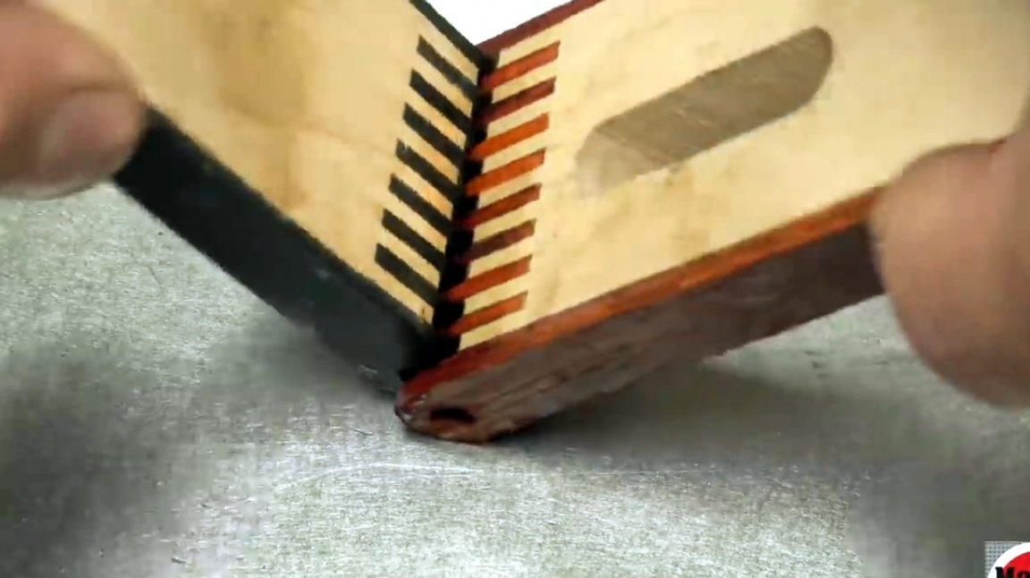
To give the box connections strength, the craftsman cuts slots into them.
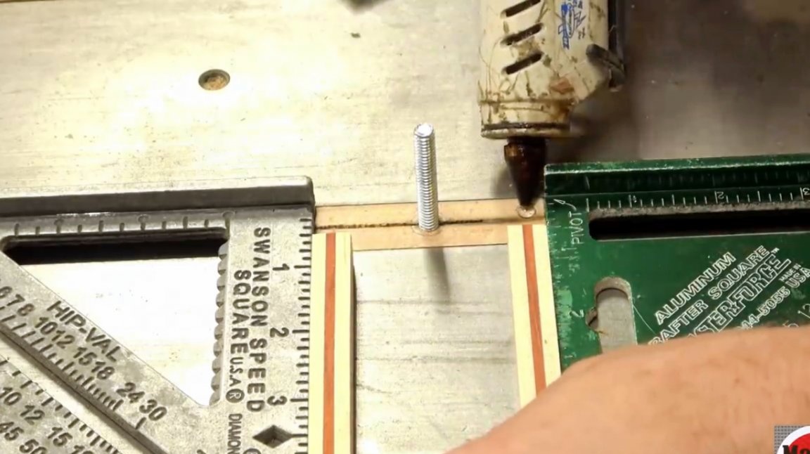
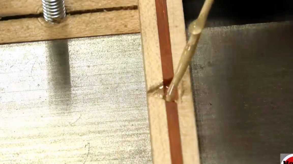
Now he attaches the guide itself to the device no longer with wood glue, but with hot glue.
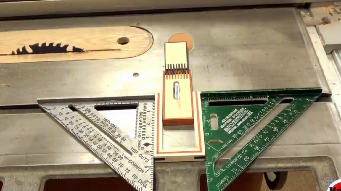
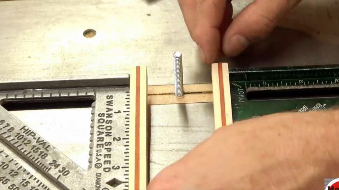
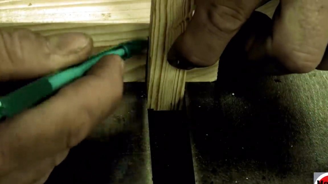
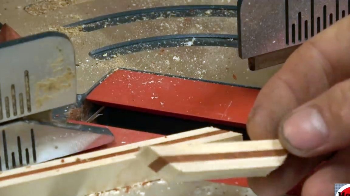
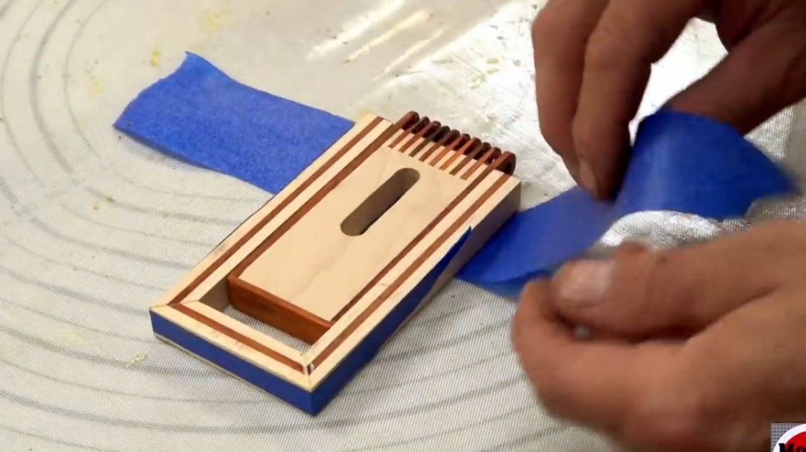
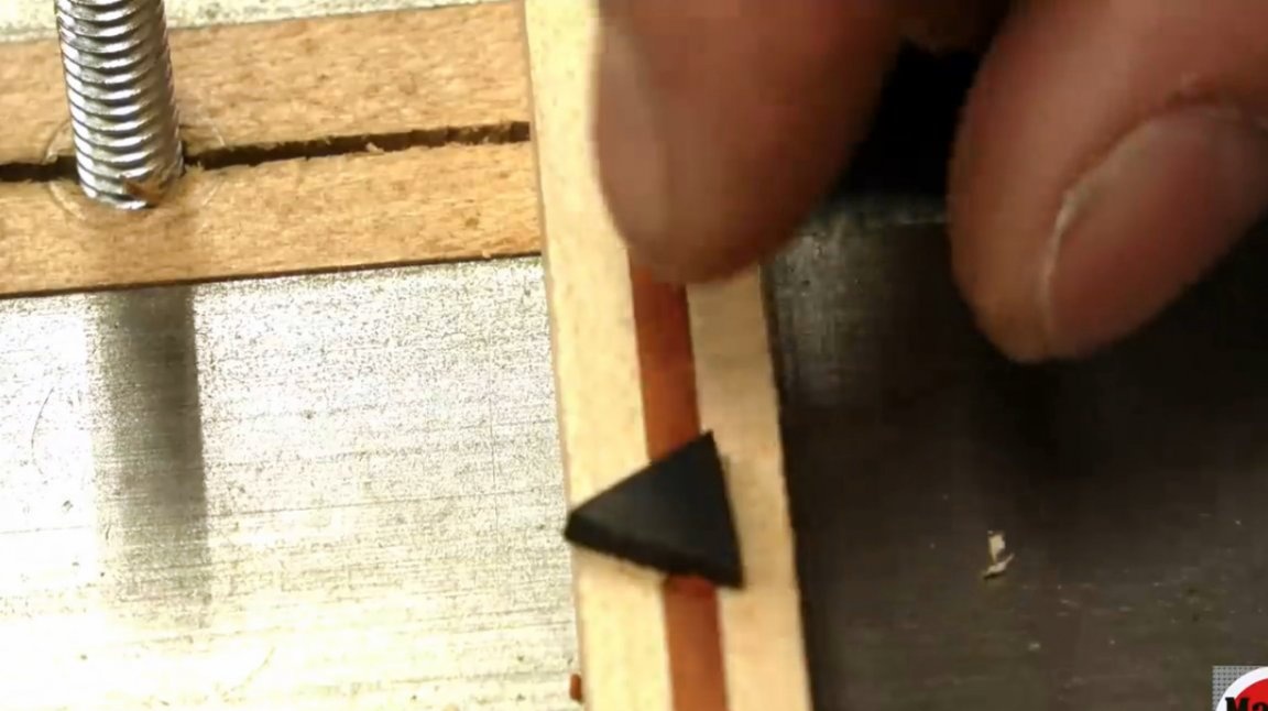
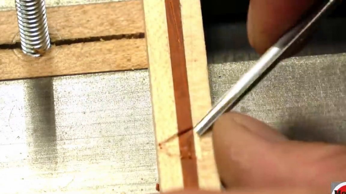
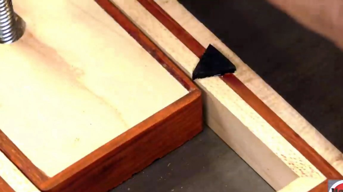
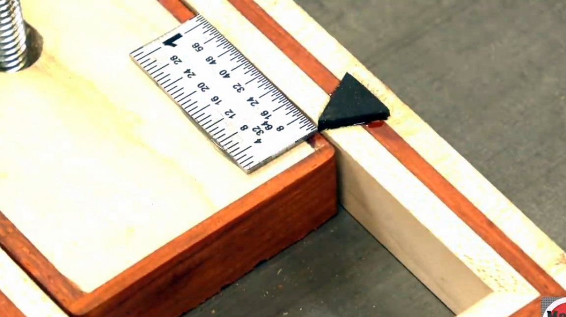
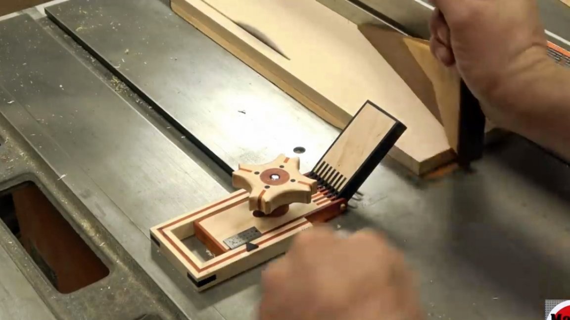
Instead of leaving a serif with a chisel, as was done on the first sample, the author cuts a neat triangle from wood of contrasting color, outlines it and cuts a chisel indentation of the same shape inside the applied contour. In addition, the author rejects the idea of drilling holes in the measuring scale. Instead, he fastens it to the casing with epoxy.
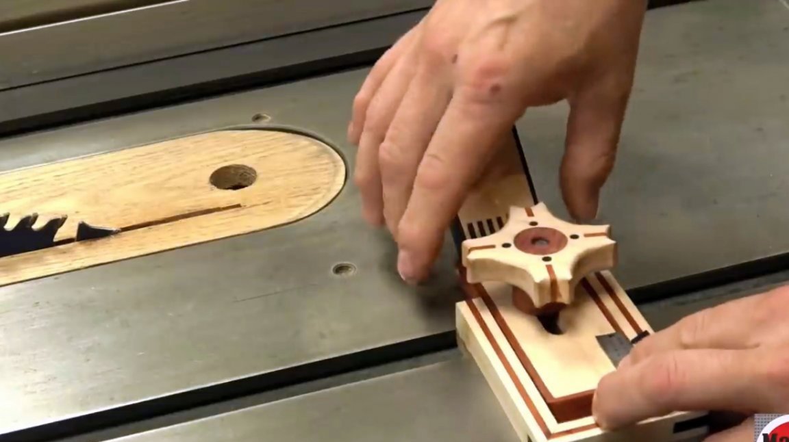
A plastic lamb replaces homemade.
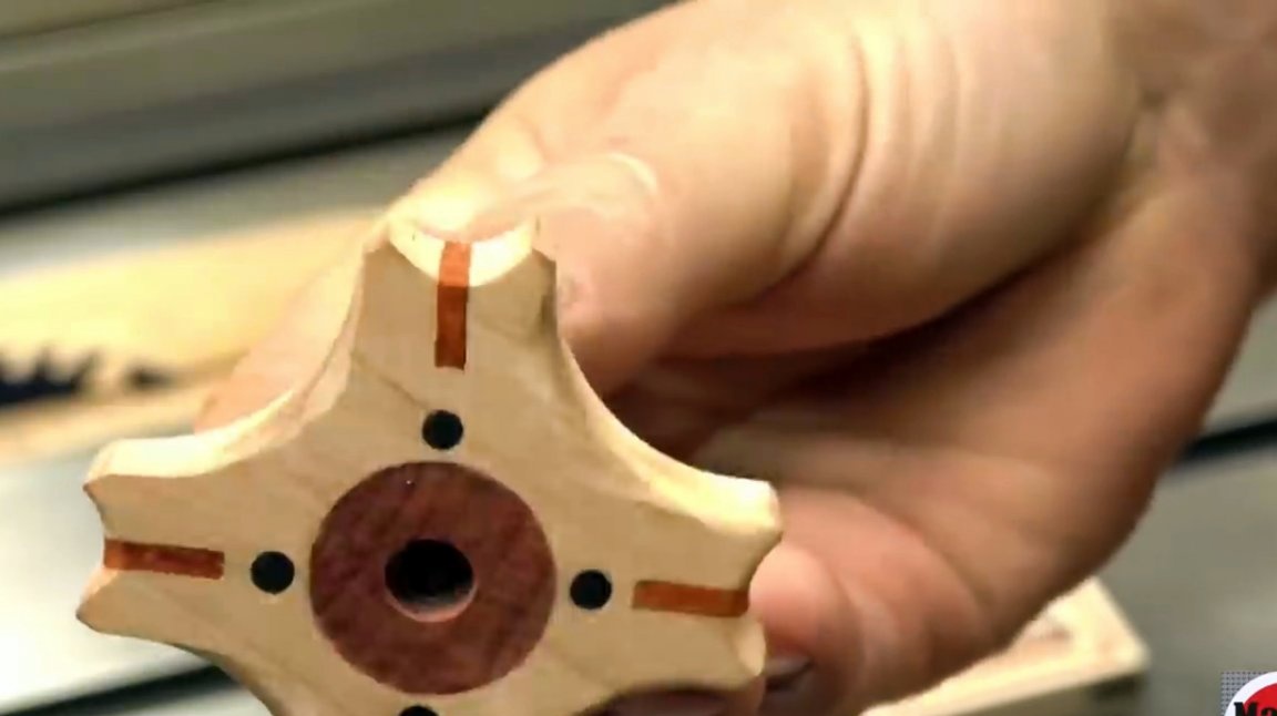
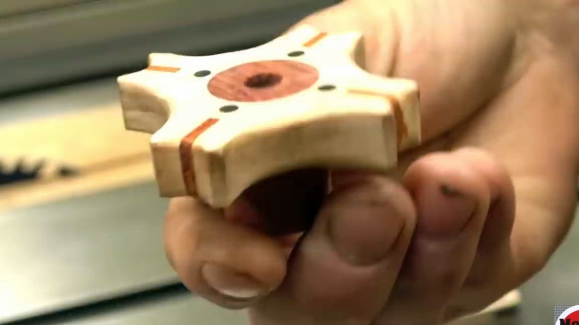
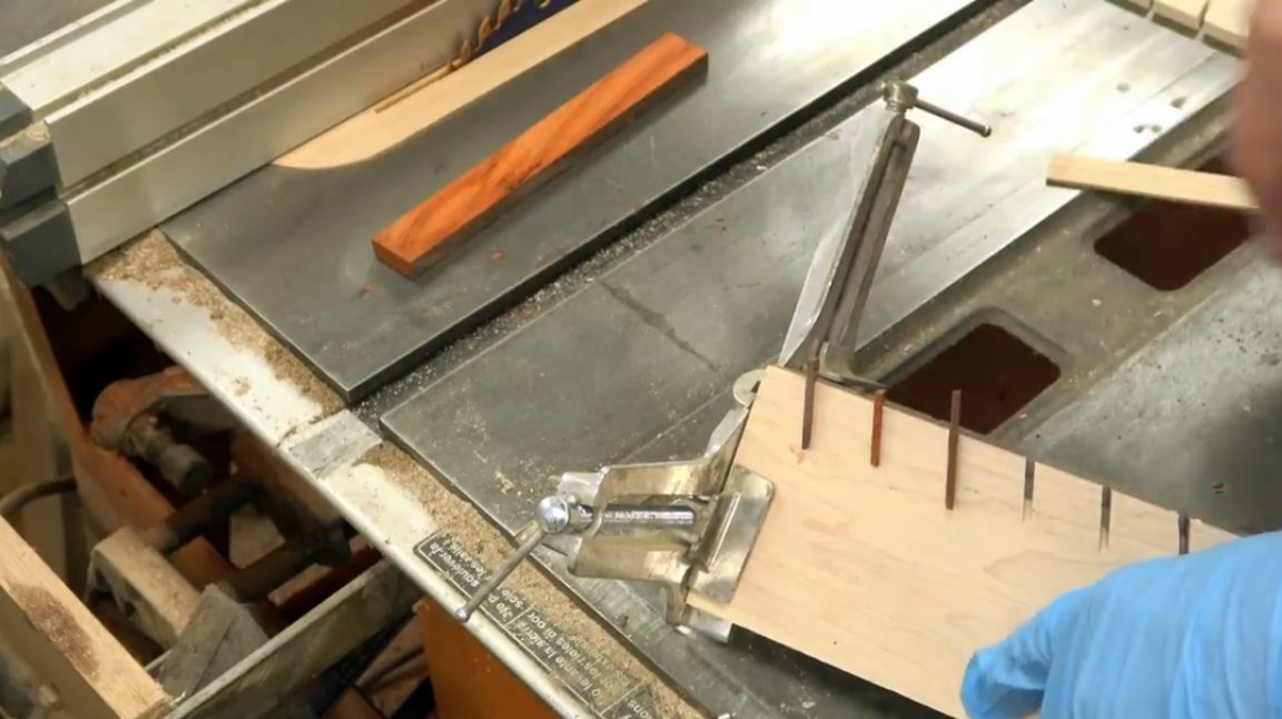
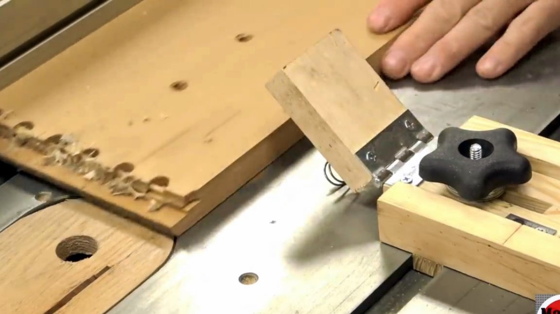
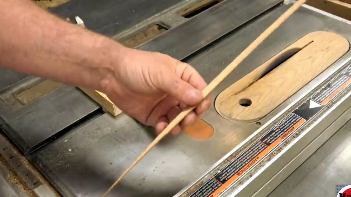
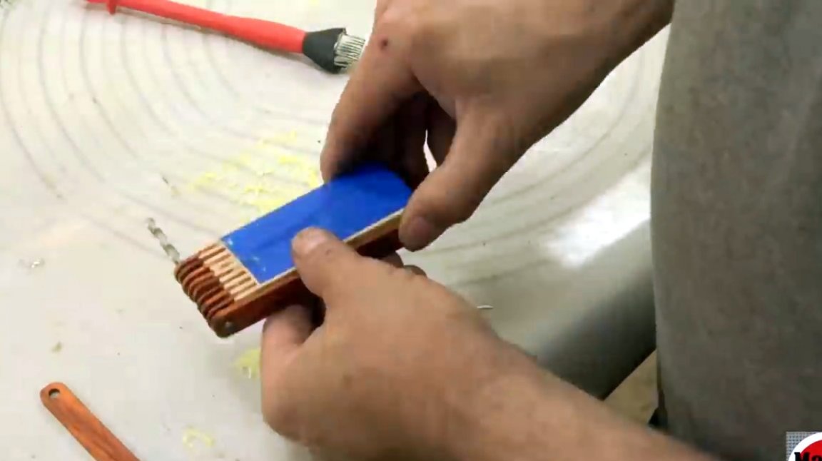
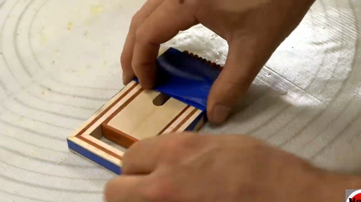
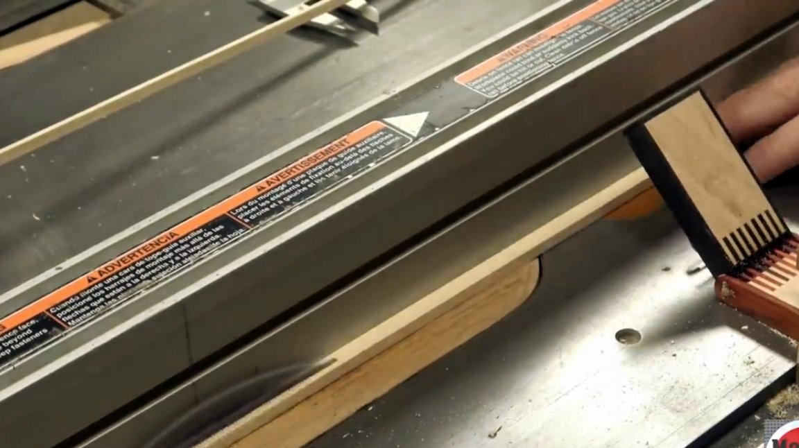
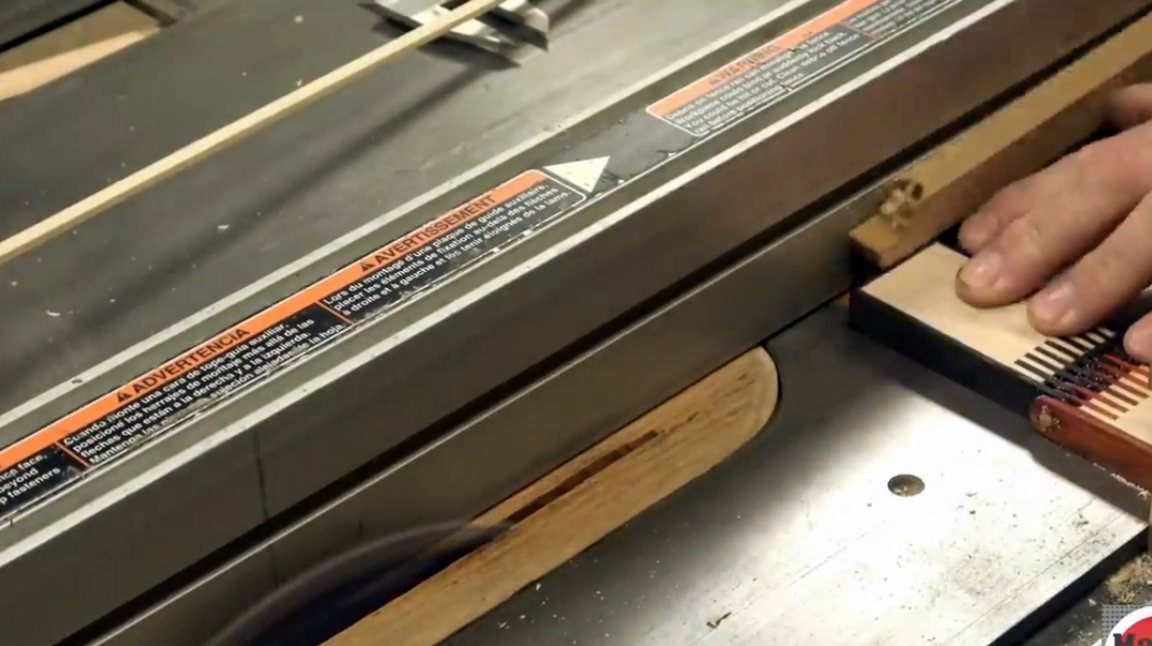
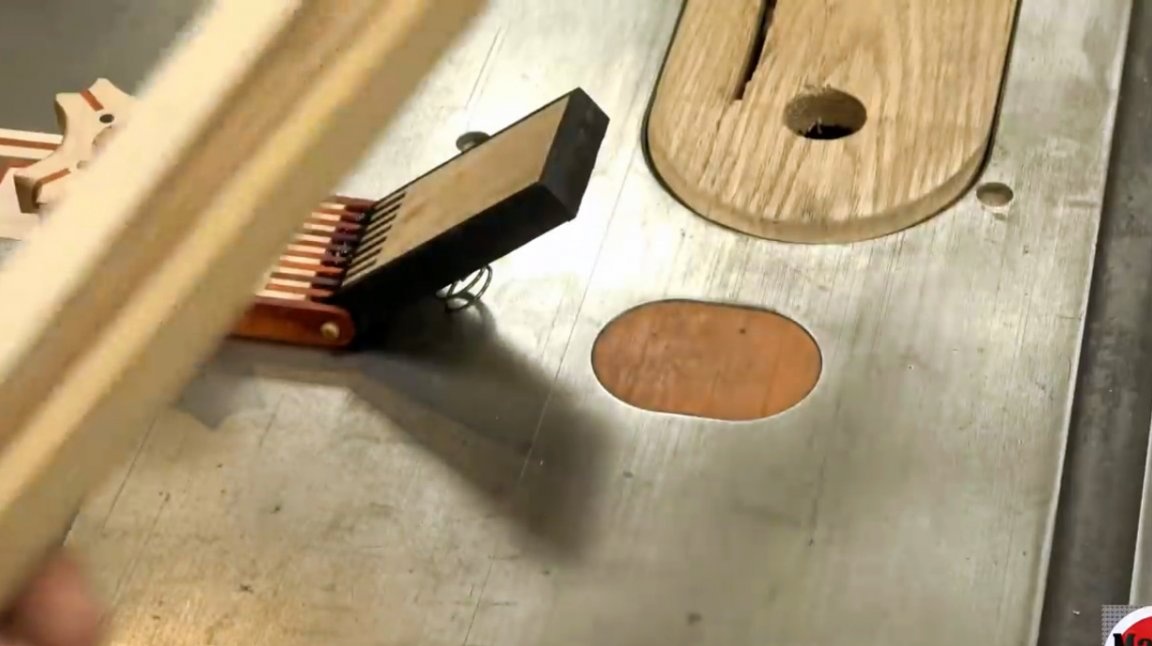
And here is what a new device for cutting thin plates of wood looks like.
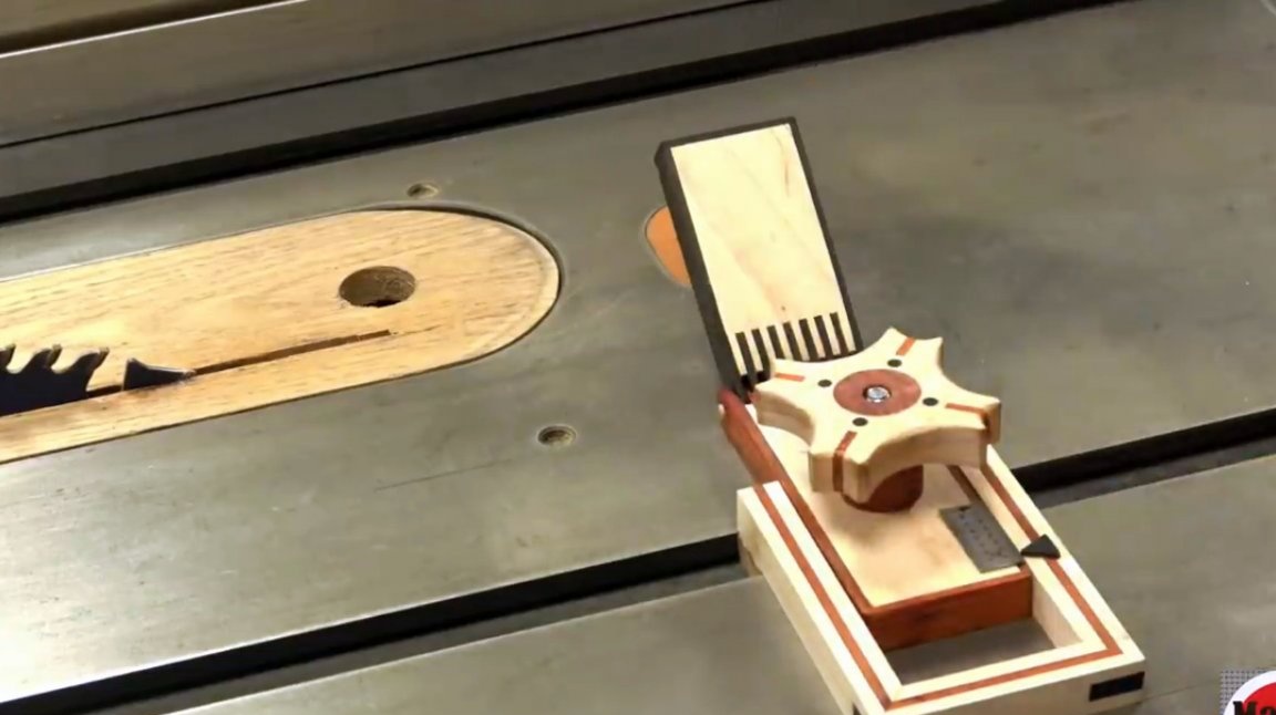
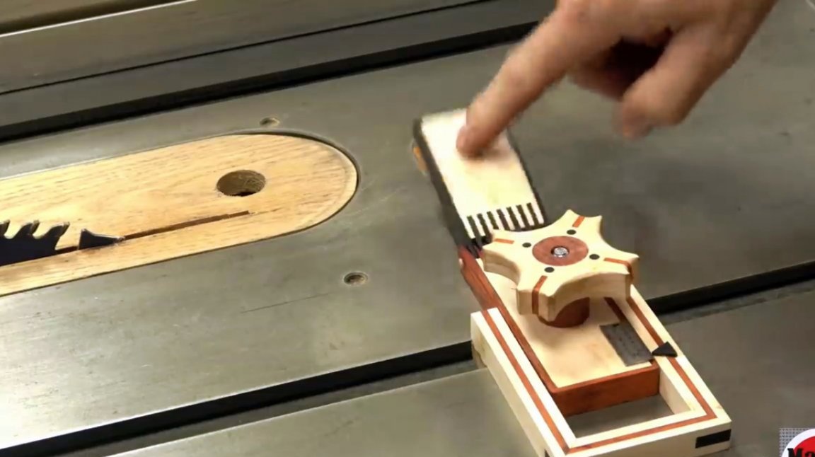
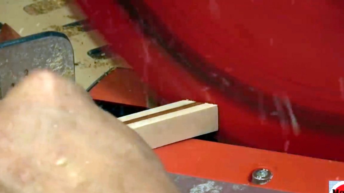
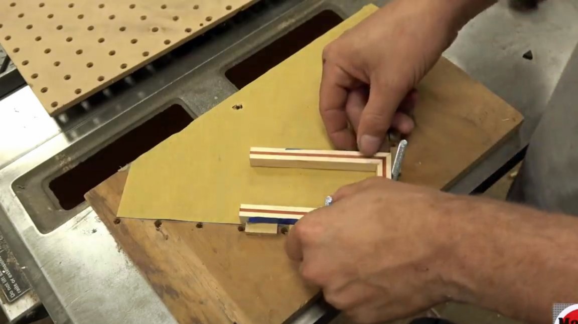
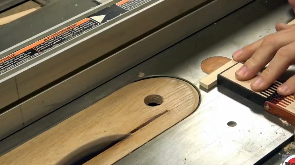
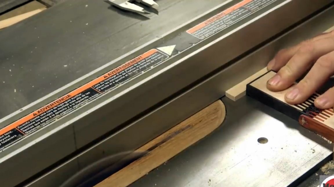
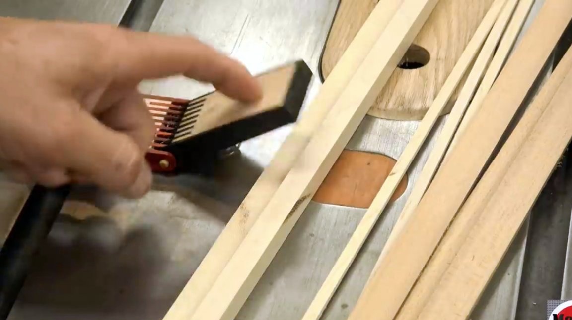
And here is how the device manifests itself in action.
And a few more experiments. Of course, all surfaces of the product must be coated with impregnation or wax.
I thank the author for a simple but useful tool for a circular saw!
All good mood, good luck, and interesting ideas!
Author video can be found here.