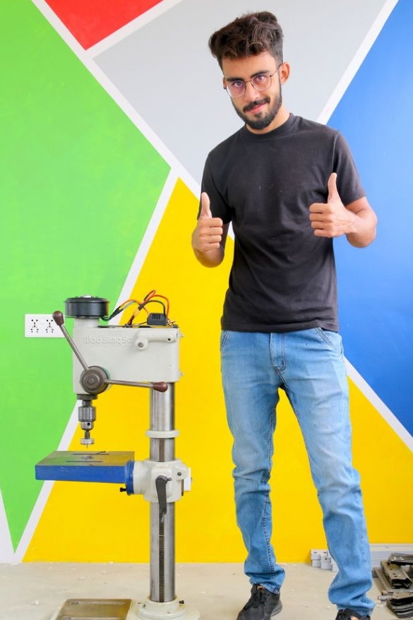
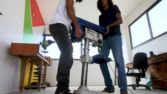
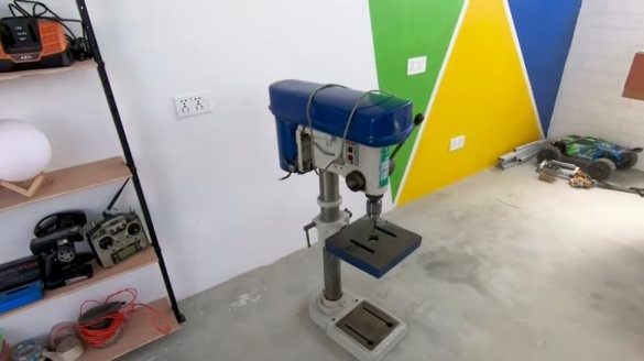
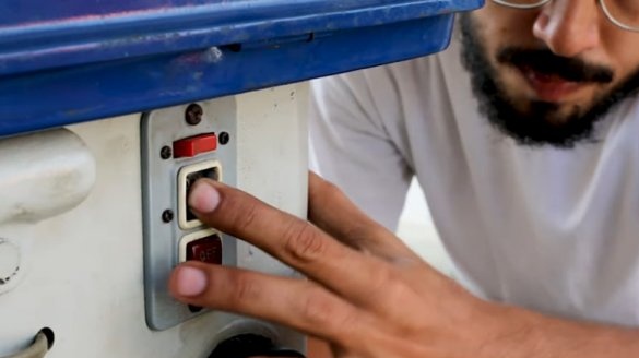
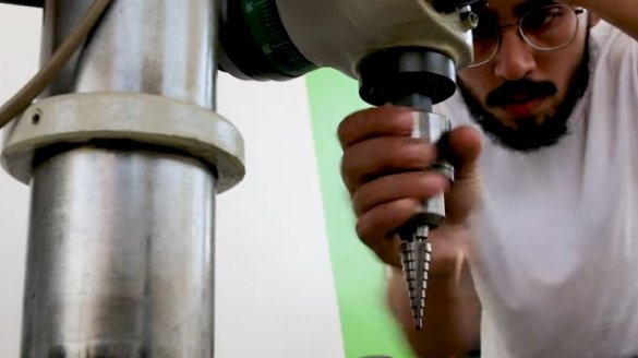
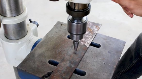
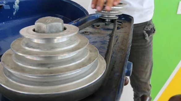
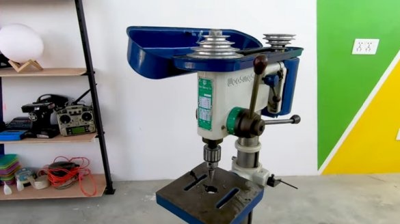
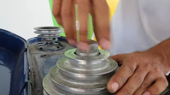
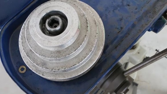
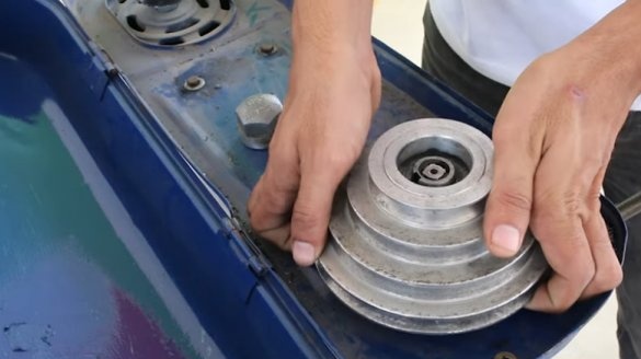
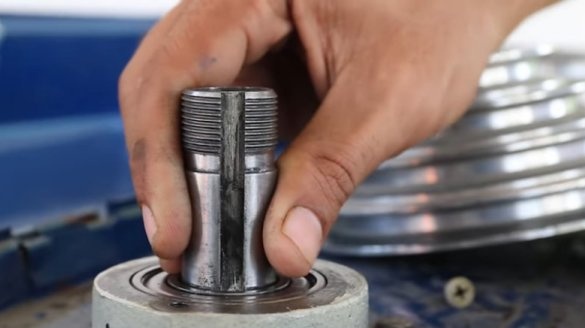
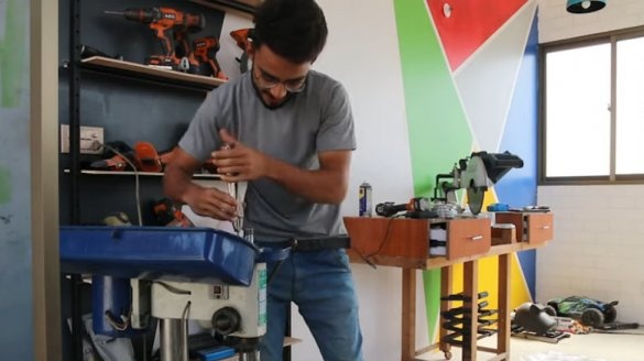
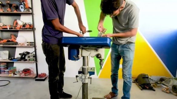
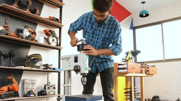
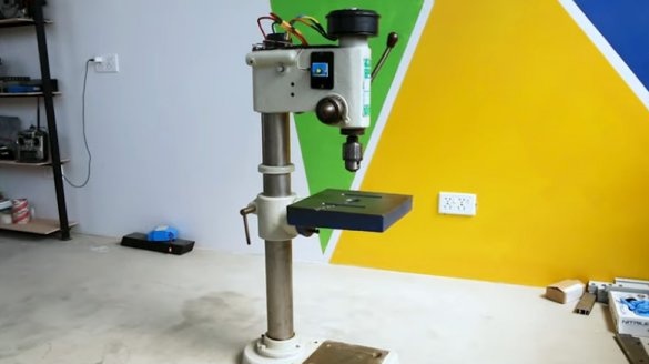
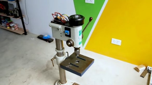
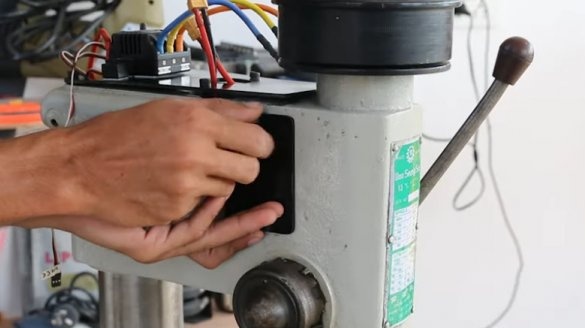
A student from Pakistan acquired an old drilling machine. There was an old bulky motor on the machine, which transmitted force to the machine shaft through pulleys and a belt. The engine was started only after putting it into action by hand and stopped with little effort during drilling.
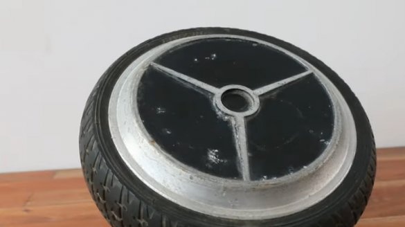
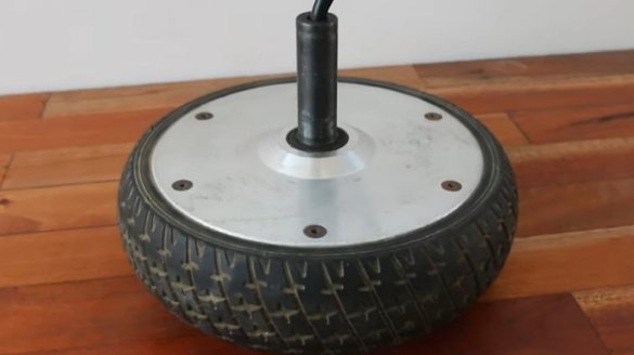
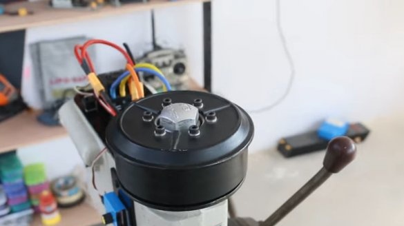
Then the idea arose to dismantle the old engine and belt drive, and instead install the engine from the gyroscope. Such an engine has a large torque and can be mounted on a machine shaft without a pulley system.
Tools and materials:
-Drilling machine;
-Engine from a hoverboard;
-Screwdriver;
-Drill;
- Canvas for metal;
-Metal plate;
-Clamp;
-Tap;
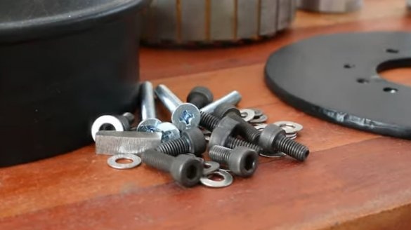
-Fasteners;
-Paint;
-Brush;
-Thermal insulation;
-Tester;
-Nippers;
-Soldering accessories;
-Motor controller
- Controller TS150 SK-300045;
-Lithium polymer batteries;
-SERVO-TESTER;
-Double sided tape;
-Plastic sheet;
- Metalwork keys;
Step one: reworking the mechanical part of the engine
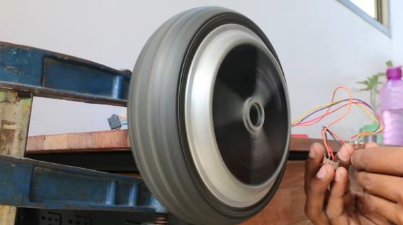
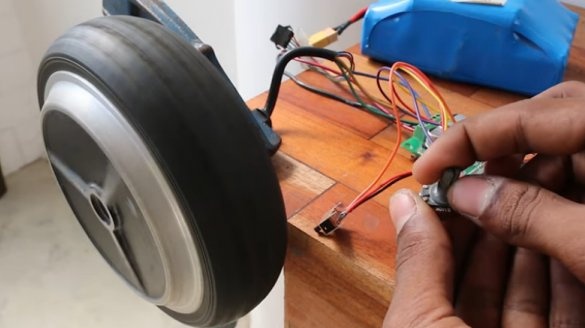
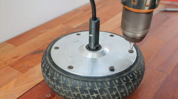
First, the wizard checks if the hoverboard engine is working.
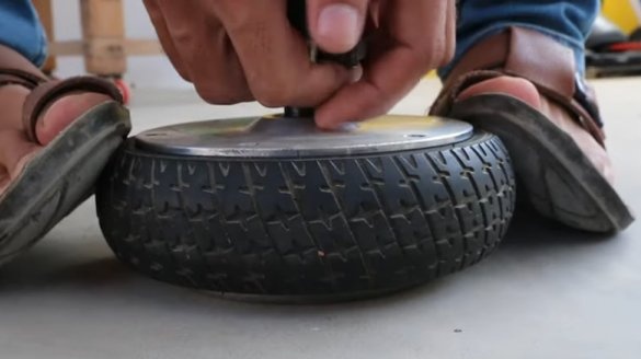
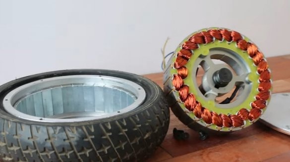
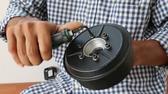
Everything works, and he disassembles the engine.
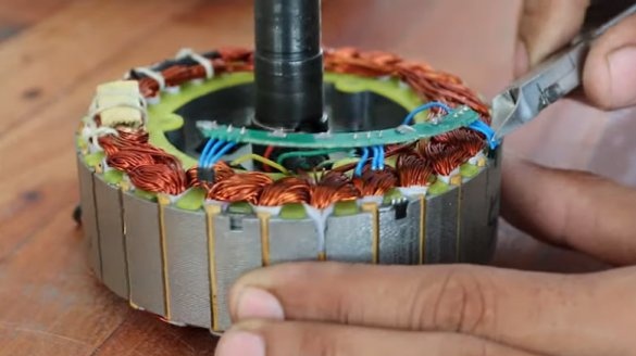
Deletes the board.
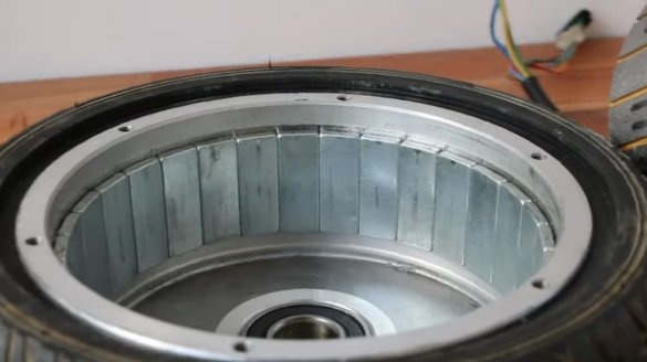
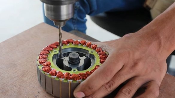
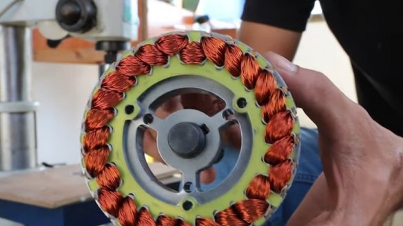
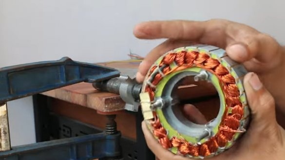
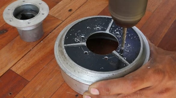
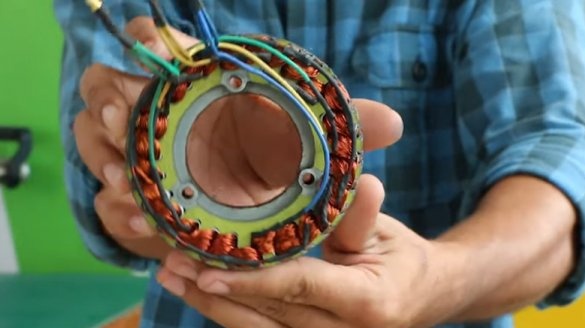
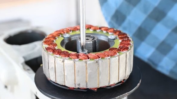
Now you need to remove the internal partitions on the stator. The master drills holes and cuts out the middle part.
Step Two: Adapter Plate
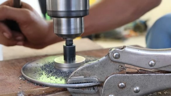
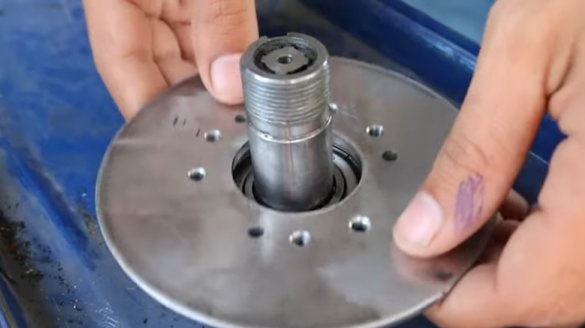
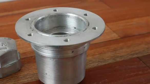
To fix the stator, the master cuts a plate out of metal.
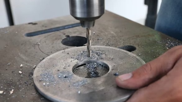
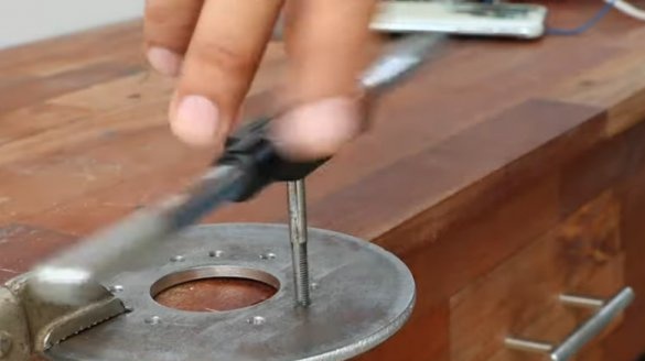
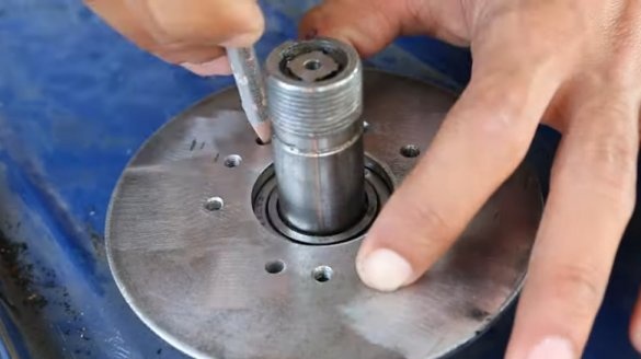
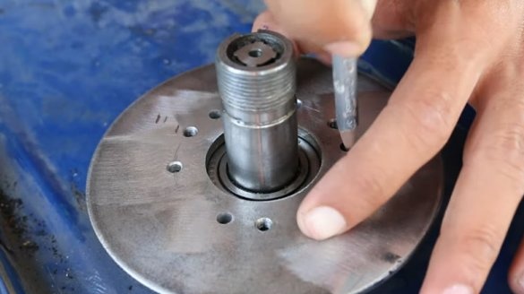
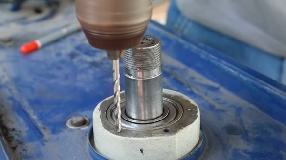
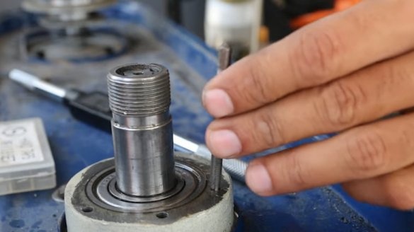
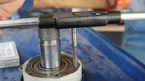
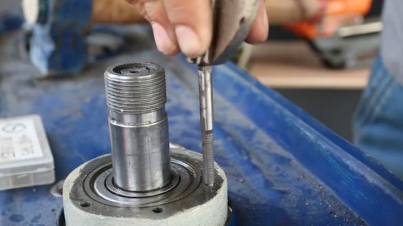
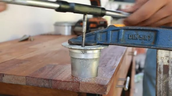
Drills holes and cuts threads.
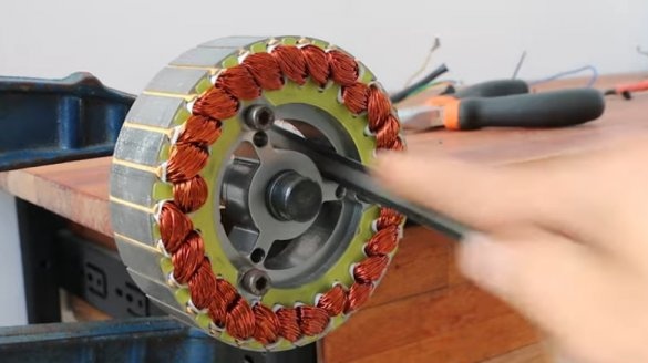
Drills holes and cuts threads in the bearing housing.
Step Three: Rotor
Now you need to figure out how to install the rotor.
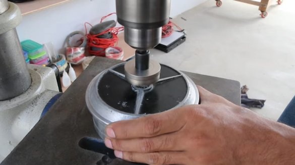
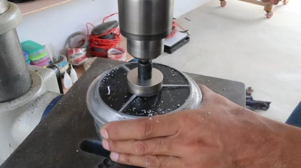
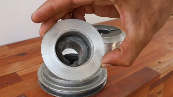
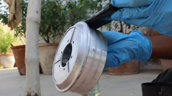
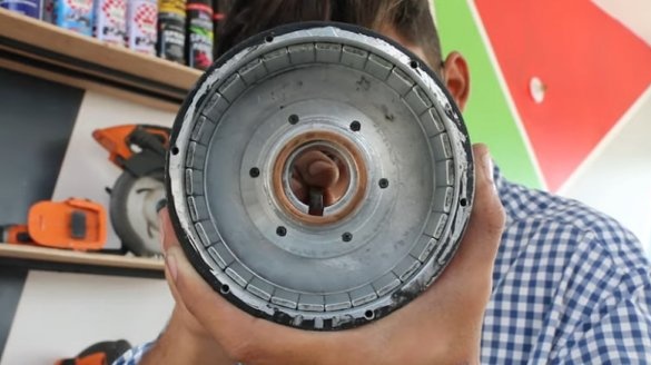
The master cuts a hole in the center of the rotor.
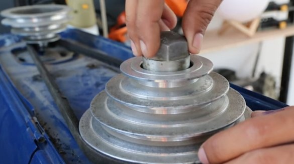
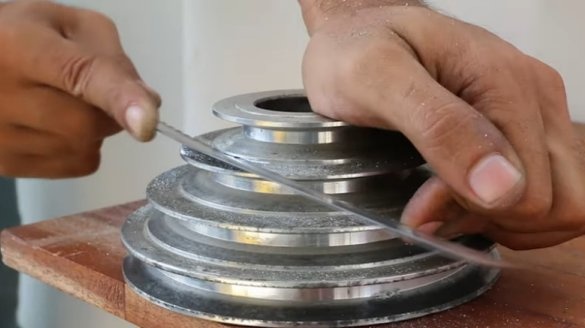
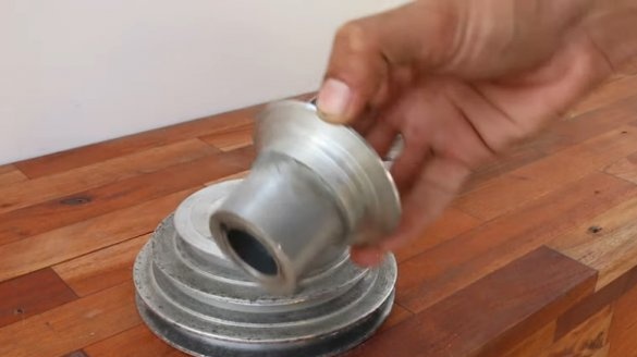
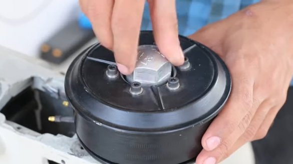
From the pulley cuts off the upper part.
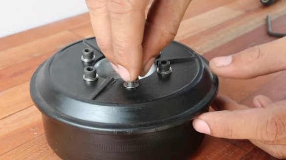
Drills holes in the rotor and pulley coaxially. Cut the threads into the pulley holes.
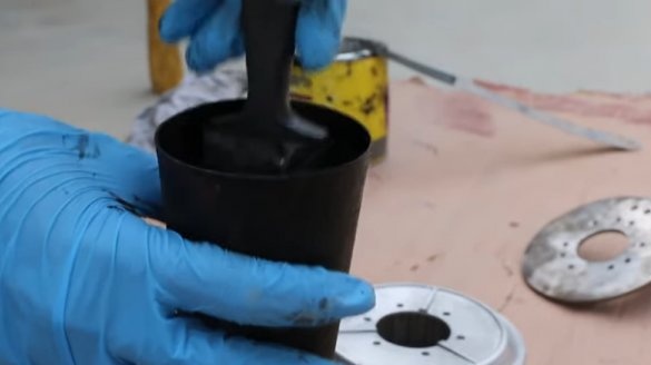
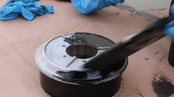
Stains the rotor and the plate black.
Step Four: Winding Alteration
The first problem that the master encountered was a rotor jam in the stator. When processing both parts, a gap of 0.5 mm was violated. The only solution that the master could find in these conditions was to grind the rotor.The master carefully polished the inside of the rotor and eventually the problem was solved.
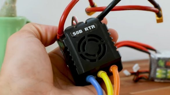
The next problem with the speed controller. Initially, it was thought to install a cheap Chinese regulator that can control the engine of a gyro scooter. But the motor could not reach the set power with this regulator.
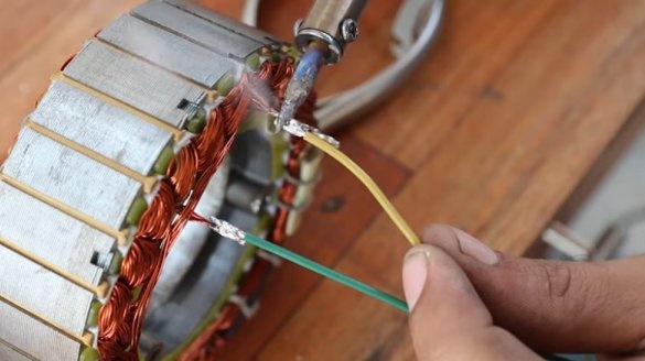
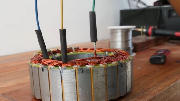
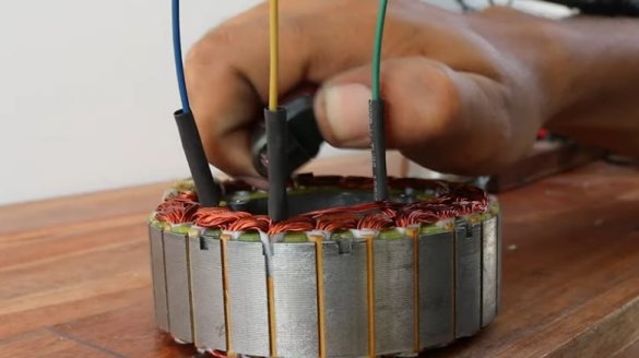
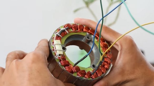
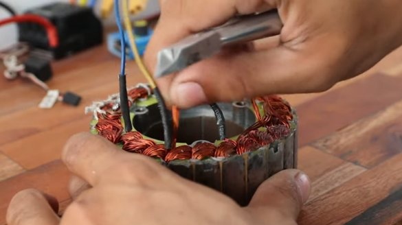
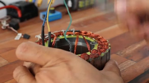
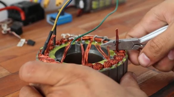
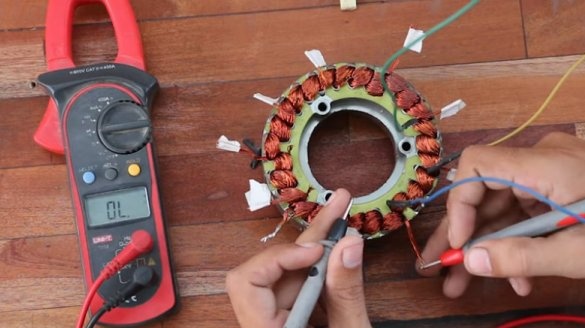
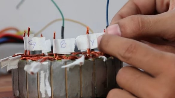
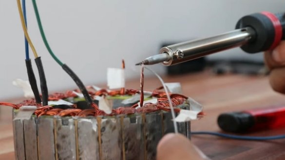
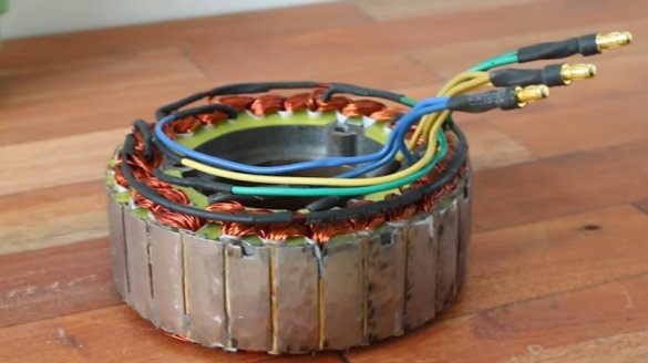
Then the master replaced it with a more powerful one with a nominal value of 150 A and 6 cells. Initially, the engine is designed for 10 cells, which is almost 42 V, and provides decent speed, so when using an ESC operating on 6 cells (25.2 V), the speed will be insufficient. The master had to redo the winding.
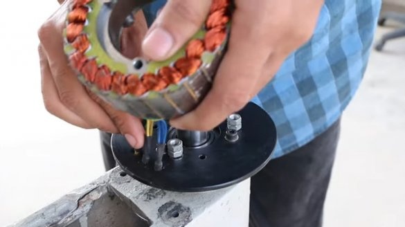
Now the engine can be assembled and its operation checked.
Step Five: dismantling the old and installing a new engine
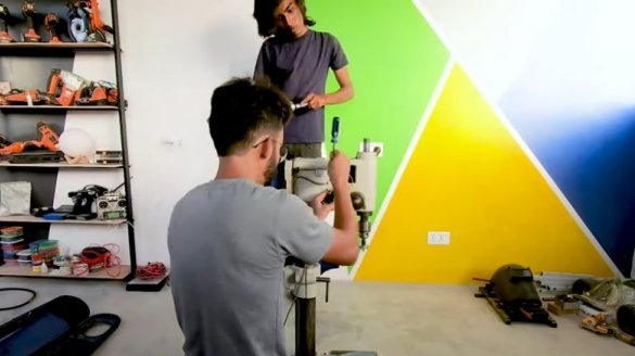
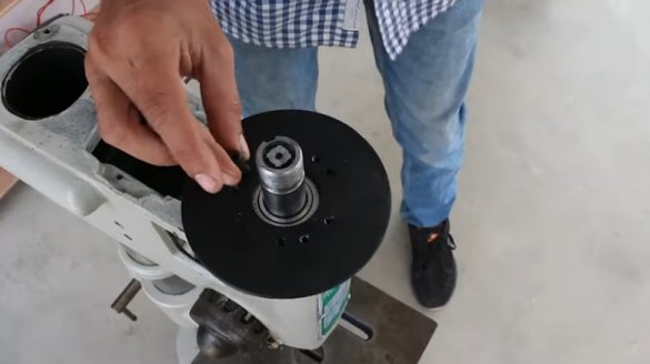
Next, the master dismantles the old engine.
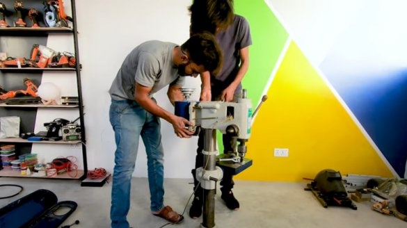
Installs a new engine
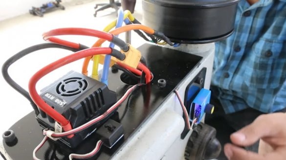
Step Six: electronics
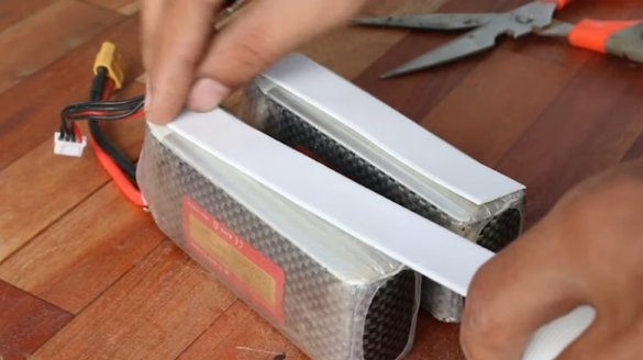
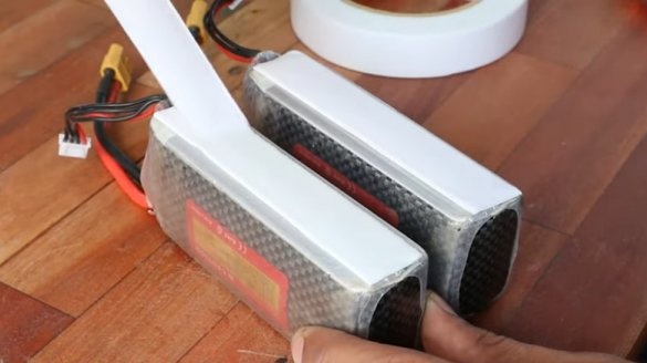
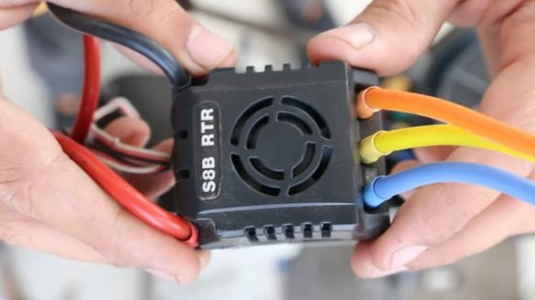
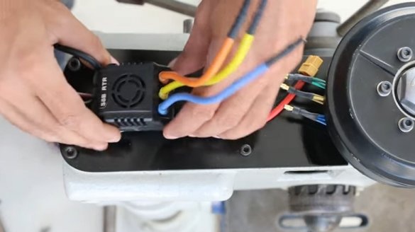
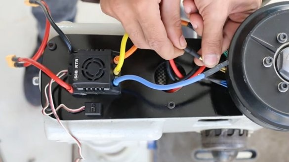
To power the brushless motor, the master is going to use a speed regulator designed for 150 A and 6 cells (25.2 V), and to power lithium-polymer batteries. Each battery consists of three cells (11.1V).
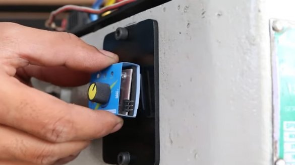
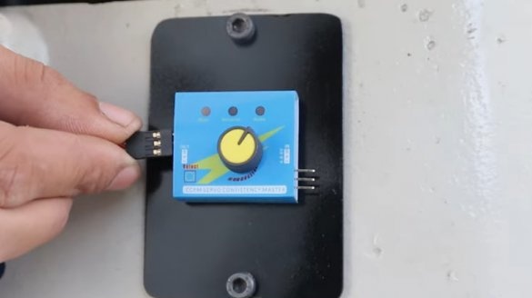
To control the ESC manually and control the engine speed, the master uses a servo tester.
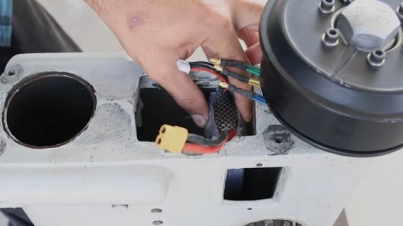
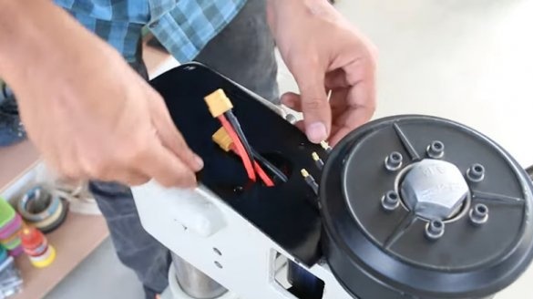
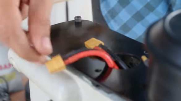
Installs batteries
controller,
servo tester.
All is ready. Then the master conducts the tests.
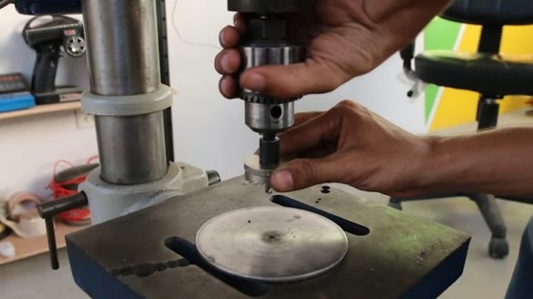
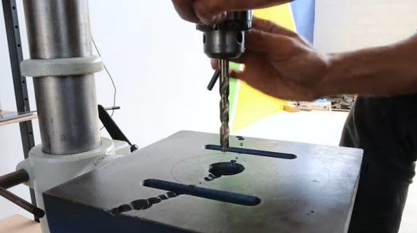
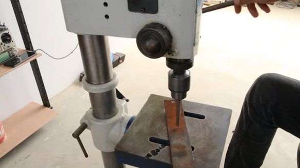
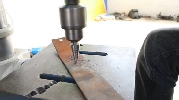
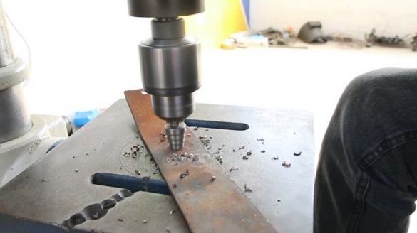
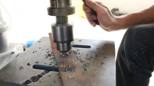
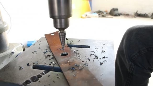
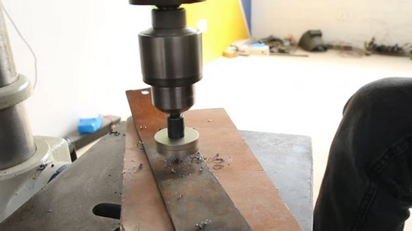
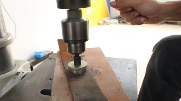
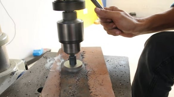
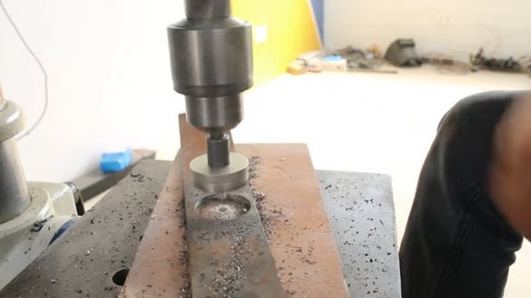
Installs the drill and turns on the engine.
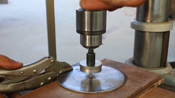
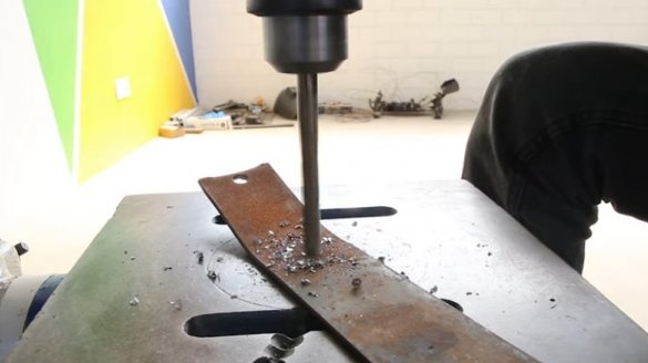
He will drill a metal plate.
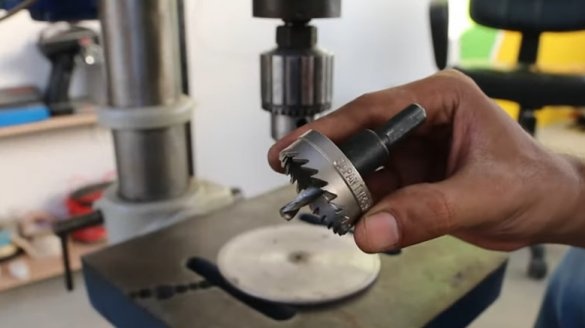
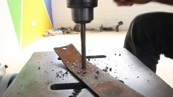
Both conventional and cone drills can easily do the job. Then the master sets the crown.
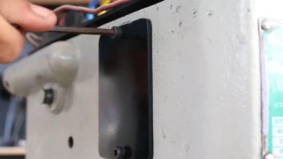
No complaints about the work. In the future, the master plans to make a cover on the engine compartment and install a BMS board.

