Hello, friends the inhabitants of our site! Many of you have been able to repair failed radios and low frequency amplifiers.
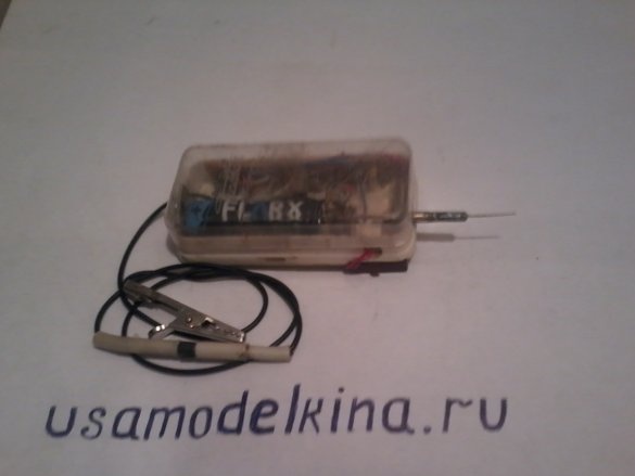
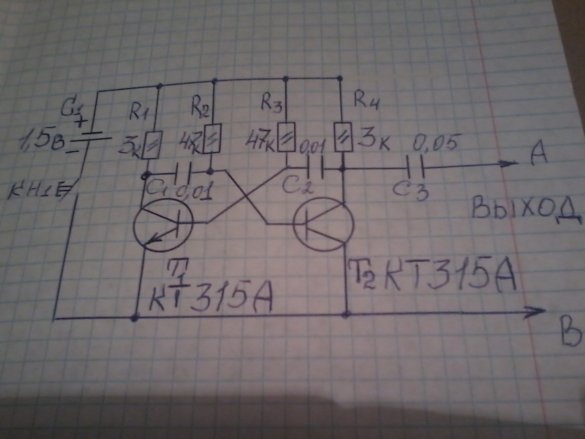
The next home-made, which I did, is just useful for these purposes. This is a simple signal generator that can be used to check not only the sound path of the receiver, but also the radio frequency. His diagram is shown in the photo.
This is an ordinary multivibrator that generates oscillations not only of one fundamental frequency, but also many more multiple frequencies, called harmonics, up to the frequencies of the short-wave range.
The generator consists of two transistors. The output voltage taken from the resistor R4 through the isolation capacitor C3 is fed to the input of the amplifier or receiver we are testing. If an undistorted tone sound corresponding to the oscillation frequency of the generator is heard at the output of the receiver or amplifier in its loudspeaker, then the devices we are testing are faulty. And if the sound is distorted or completely absent, then this indicates a malfunction in their circuits. To create a homemade product, we need the following parts and tools.
it: two transistors KT 315A, MLT resistors - 0.25 W 3 kom - 2 pcs, 47 kom - 2 pcs, capacitors 0.01 μk -2 -, 0.05 μF - 1 pc, any small button, 1.5 V battery, one clip "crocodile".
Instruments: soldering iron, tweezers, solder, mounting wires, wire cutters, pliers, small case, needle, M2 screws and nuts, brass plates for the battery holder, mounting circuit board measuring 1.5 cm * 7 cm.
We assemble as follows:
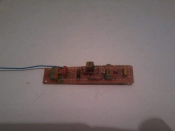
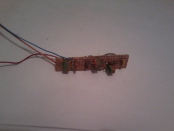
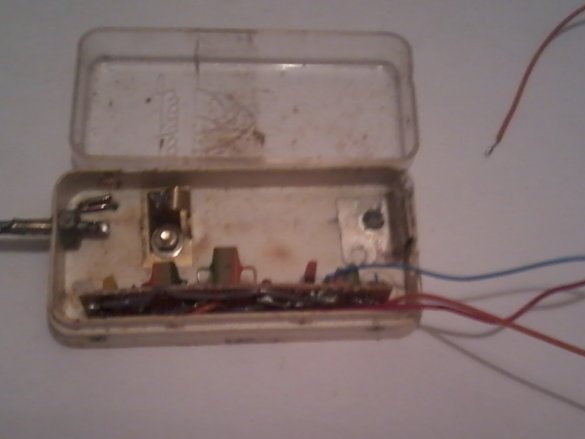
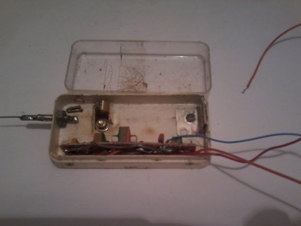
Step 1. We check all the radio components for their performance with a multimeter. We solder the whole circuit on the printed circuit board. Check the correct assembly.
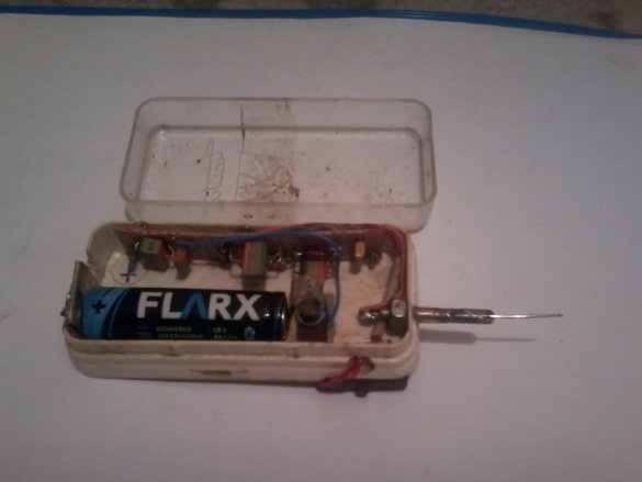
Step -2. In the case we have, we fix the button and the battery holders.
We put the battery in the case, connect the soldered board. We connect the head phone to the “A - B” output, and check the operation of the generator on the table. If the circuit is assembled correctly, then it starts to generate sound signals that are heard in the headphone.
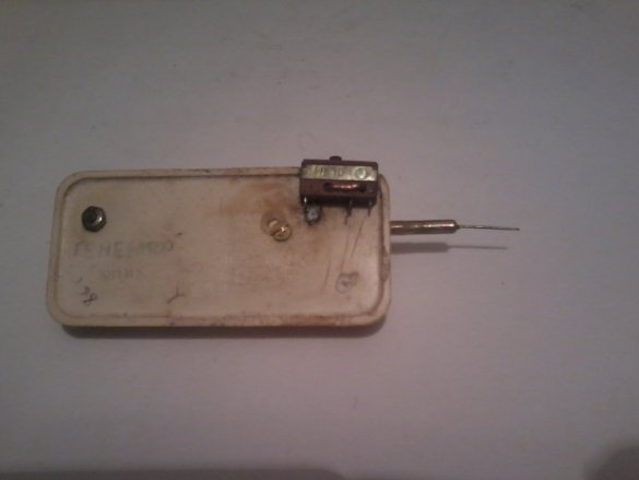
Step -3. We fix the board into the case, solder the output “A” to the needle, and the output “B” - we bring out the black wire with the crocodile clip soldered at its end.
Close the case with a lid.
The main frequency of the signal is about 1 kHz, the output signal is about 0.5 V, the current consumption is not more than 0.5 mA. The batteries last for a whole year.
That's all, the homemade product is ready. And whether you need it - decide for yourself.
Good luck to you all in your affairs. See you again.


