

A couple of weeks before I found time for this project, I saw that there was not a single sane instruction on how to make this simple airplane using regular office rubber bands. So I decided to fix this situation.
In my model, the case is made of balsa wood, but you can use any other that will be quite thin and lightweight. (I used to make from ordinary chopsticks for sushi, cut into pieces of the right size).
To make one such aircraft, you will need: (most materials are usually easy to find in the house)
- foam (I took polystyrene foam from the packaging of products)
- wood (I have a cork tree 1.6 mm thick)
- wire / pin / paper clip for screw shaft (and brake hook, if you prefer wire to aluminum can)
- aluminum can for brake hook and front end reinforcement)
- glue
- tape for foam parts (most types of glue dissolve foam)
- beads (4 pieces)
- plastic (you can take a glass of yogurt or something similar)
- rubber rings
- a tube into which the wire can freely enter and do not fit too tightly on the inside (for example, you can take an empty rod for the handle if you are going to use a paper clip)
- scissors
- construction knife / scalpel
- pliers
Here is a video showing my creation:
Step 1: Wireframe
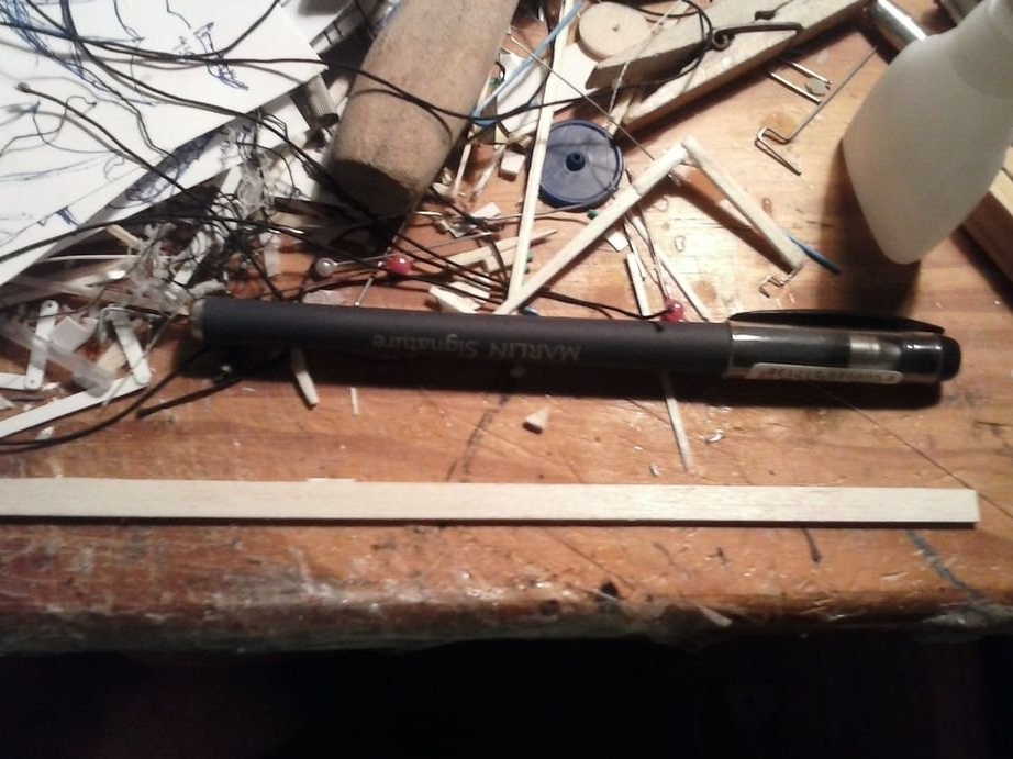
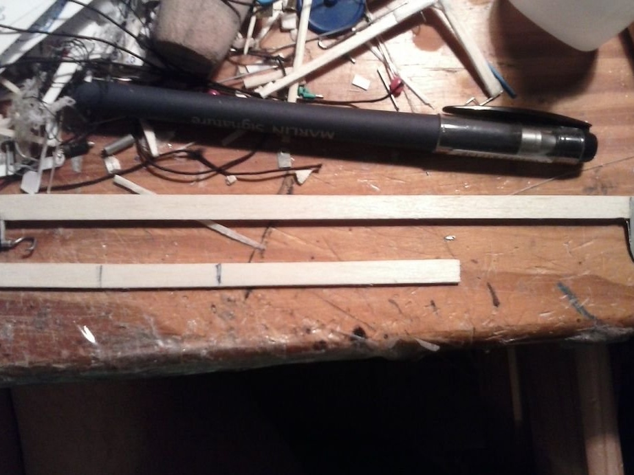
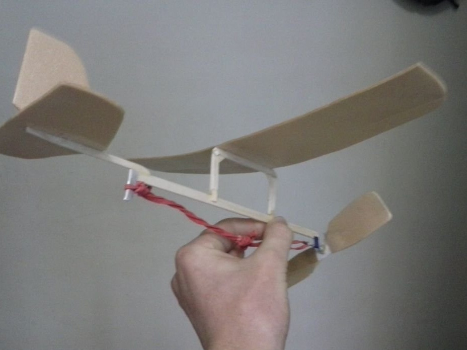
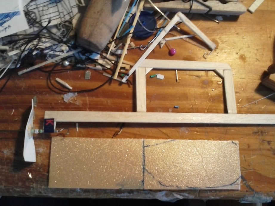
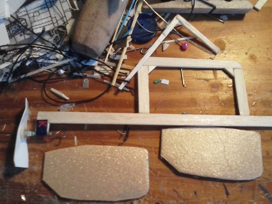
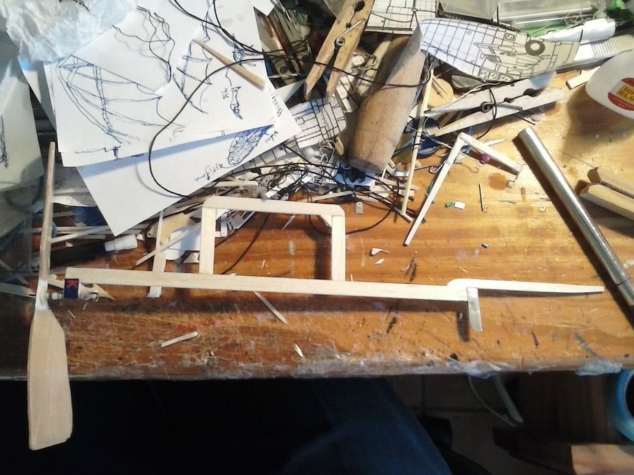
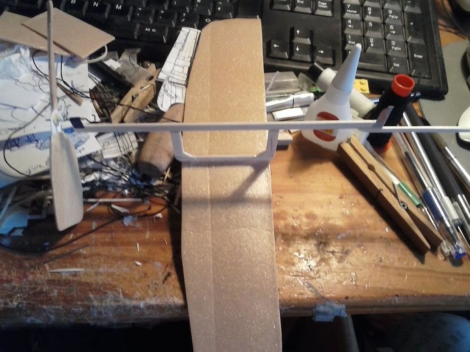
The first photo shows the final stage of this step, but I placed it at the beginning for better clarity in detail.
Start with the main beam of the fuselage, its goal is to hold the gum and be a bridge between the propeller and wings, as well as the tail. Everything is very simple, if cut from a cork, it’s just a long rectangle, thick enough not to bend under an elastic stretched along. The size can be any, depending on how large the airplane should be. The fuselage beam in my model is 185mm x 1.6mm x 7mm.
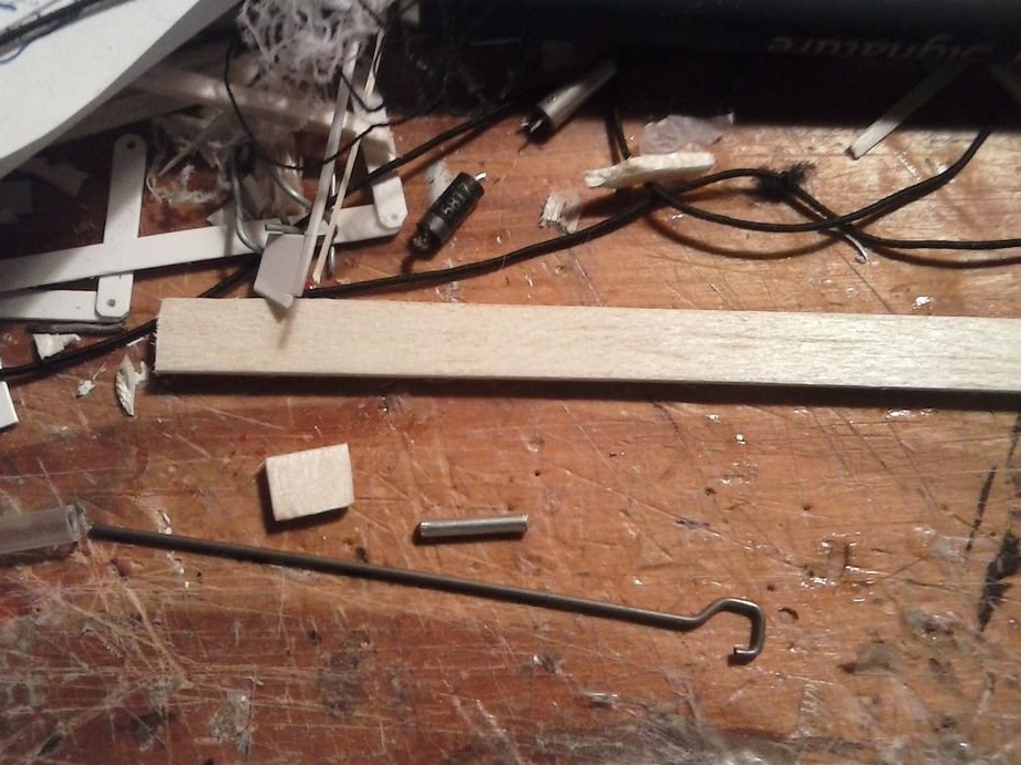
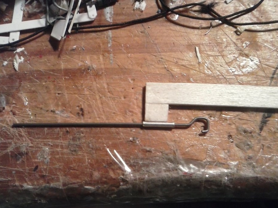
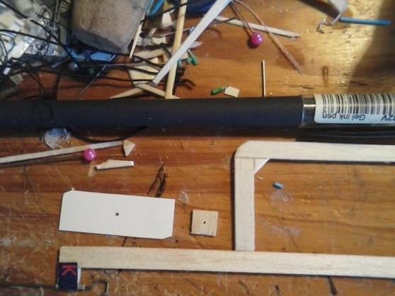
Next is the basic design of the drive mechanism. Start with three new details from the third photo - a small piece of wood (I have about 6 x 8 mm), a wire / pin / paper clip and a tube for it. Twist one end of the wire into a small hook on which the elastic bands will be held. To support this wire shaft, first glue a small rectangular piece of wood under the fuselage beam at its front end. Then glue a small piece of pipe under the tree. Insert a wire into it to check if the wire passes freely.Photo 4 shows how to arrange these elements.
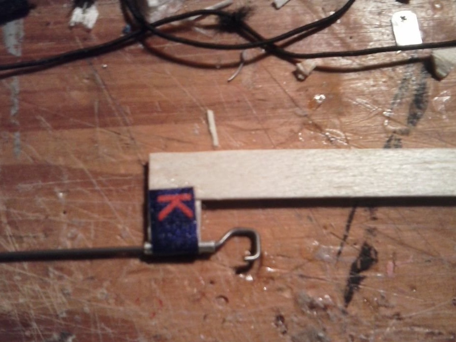
After the above preparations are finished, bend a rectangular piece of aluminum in the shape of a tall letter "U" and glue it on top of the remaining parts that you just fastened. This will strengthen the design.
To assemble the brake hook, I bent another piece of aluminum from the RedBull jar in half and pasted them with the end of the tail of the fuselage beam. You can do the same, or you can bend a piece of wire into a hook and stick it under the fuselage in the same place.
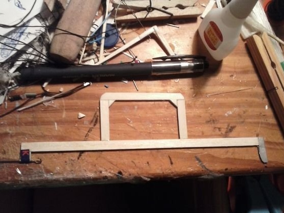
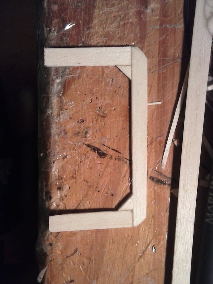
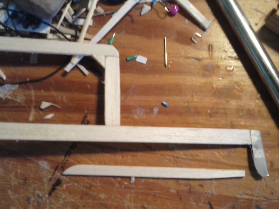
To make wing mounts, cut another piece of wood - ¾ from the length of the main beam, as shown in the penultimate photo. Divide this piece in half, and then one half in half again. Glue these parts as shown in the photo. Add small triangular pieces of wood to the inner corners of the joint, and then glue all this detail to the fuselage beam somewhere in the middle. See the first photo for clarity.
After the first test flight, I found that it was necessary to strengthen the supports for the wings and base. Glue small rectangular pieces of wood on both sides of both joints so that the wings do not break during the flight.
Step 2: Building Up the Drive Mechanism

For this step, you will need a rectangular piece of plastic (from a yogurt cup, for example), 4 beads, a small piece of wood to support the propeller hub and some foam for the propeller blades.
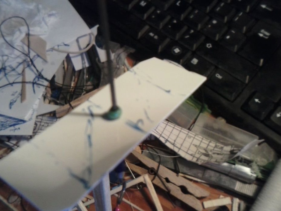
Start by cutting a rectangle with 1: 3 aspect ratios from plastic (in my model, the dimensions are 15 mm x 45 mm) and draw lines diagonally. Make a small hole (sufficient for the wire to pass) at the intersection of these lines. This will be your propeller hub.
Make a hole of the same diameter in the center of a small piece of wood, and then glue it to one side of the sleeve so that the 2 holes match.
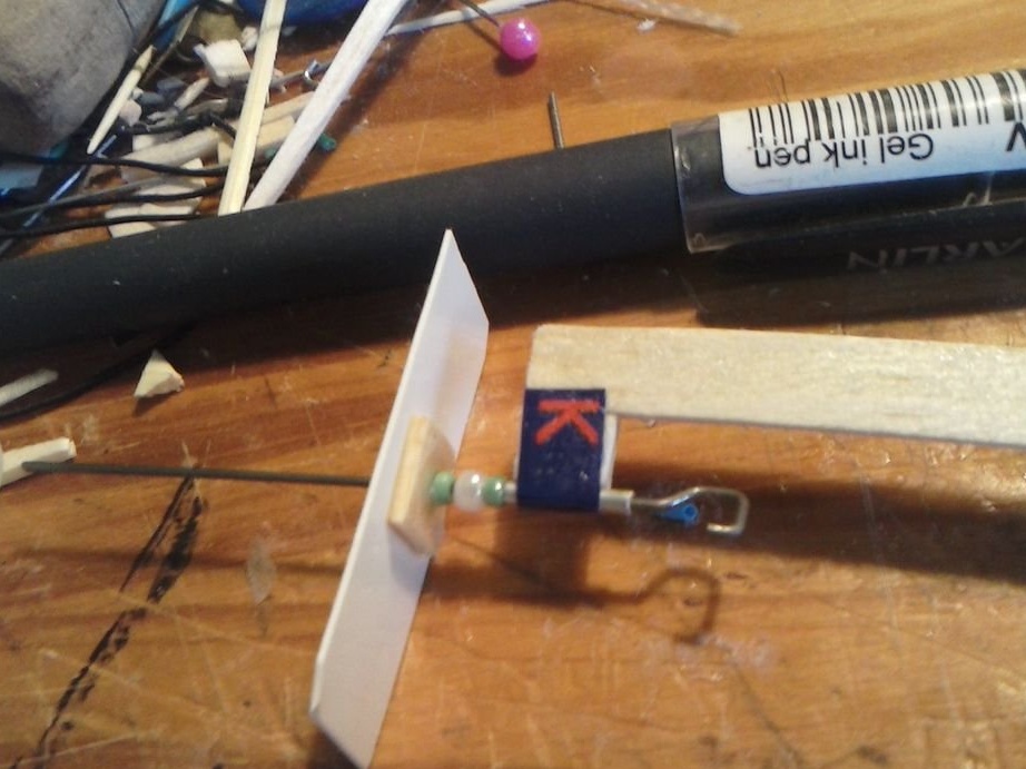
String 2 beads onto the front end of the wire shaft. Glue should not get on these beads, as they should rotate freely in the structure. String another bead, but already glue it in front of the other two. Thread the screw bushing (along with a piece of wood) onto the shaft and glue it to the shaft and the glued bead. Glue another bead in front of the sleeve so that it remains in place. Cut off the excess piece of wire protruding beyond the shaft.
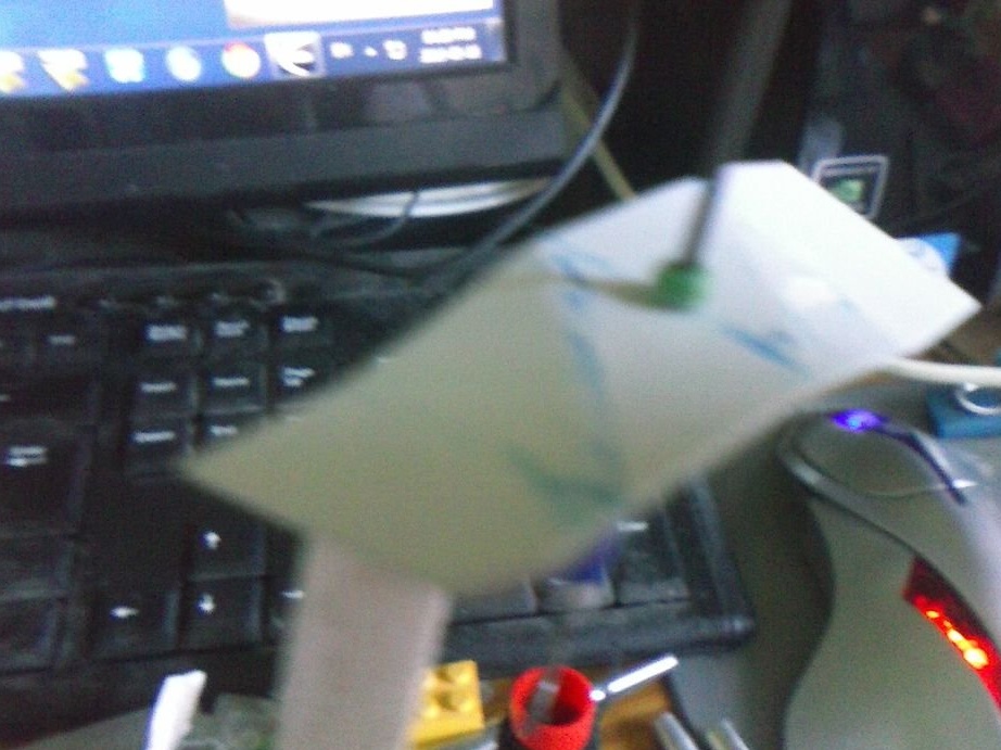
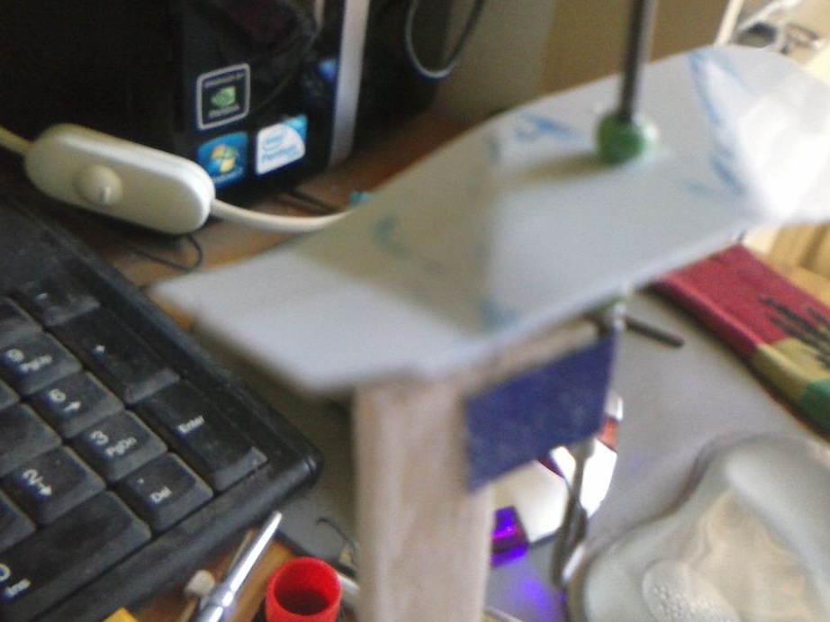
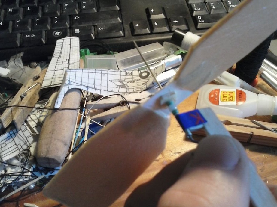
To provide the blades with a gear ratio, bend the screw bushing along the lines shown in photo 3-5. I can’t explain exactly how to do this, but I hope that the pictures will help to figure this out.
For the propeller blades you will need a piece of foam with proportions, as in photo 6. In my model, it was a rectangle measuring 130 x 30 mm. Cut it in half, along the line shown. The blades should remain rectangular, but in order to improve their performance and avoid impacts on the drive support, I suggest cutting the blades, as approximately shown in photo 7.
at the base of both blades, make a cut for the screw sleeve. Put on the blades and tape them together so that they are firmly in place on both sides of the sleeve. Look at the third from the end of the photo to see the location of the blades on the sleeve.
The blades need to be slightly bent for a better lift and a longer flight. Look at the third photo from the end. The last photo shows the complete drive system.
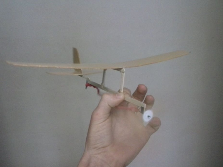
Step 3: Add Wings and Tail

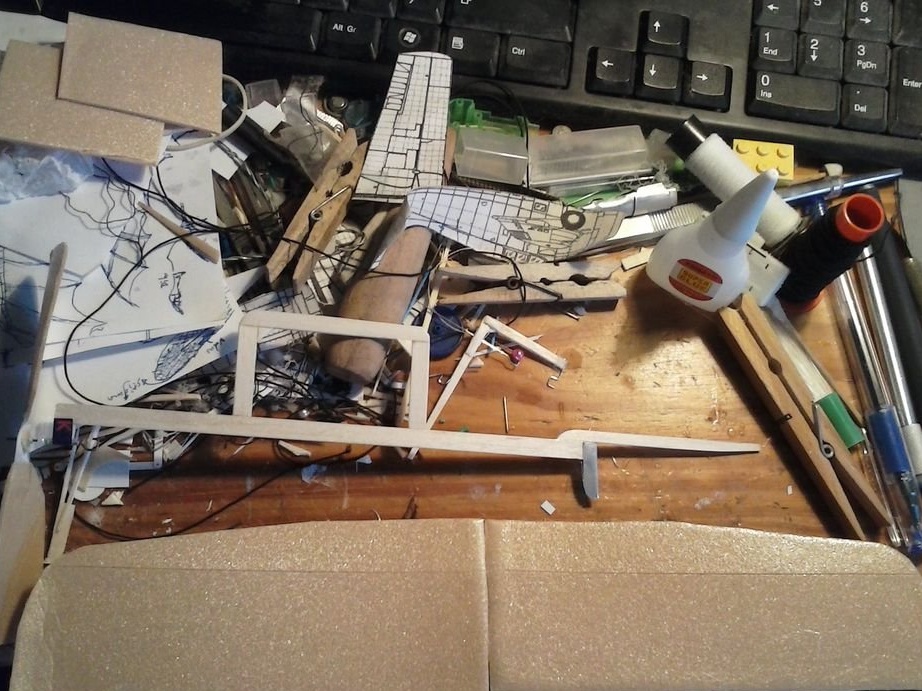
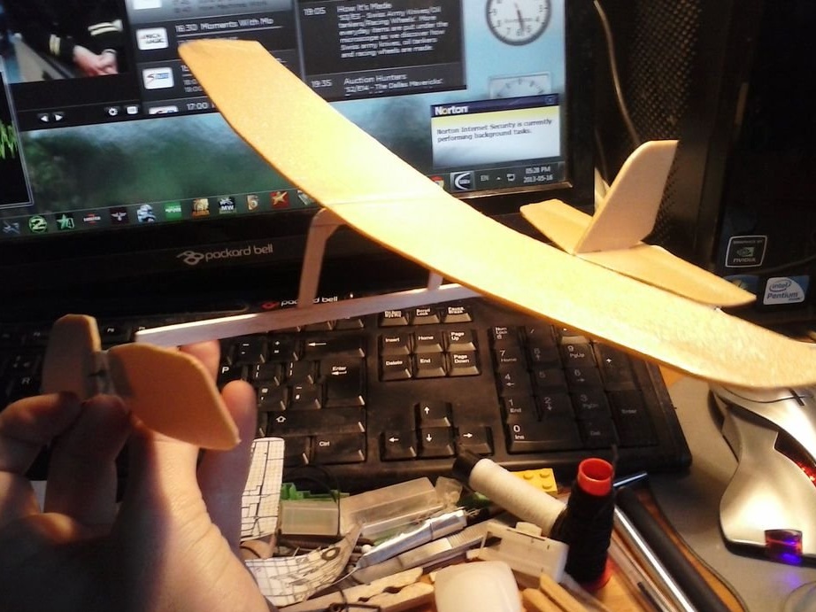
For better weight distribution, the elastic does not reach the end of the tail in this model. The fuselage should be expanded to give the necessary support to the tail. This can be done by cutting off a piece of wood with the aspect ratio shown in the photo (in my model it is 80 mm in length) and gluing the tail hook on top, as shown in photo 2.
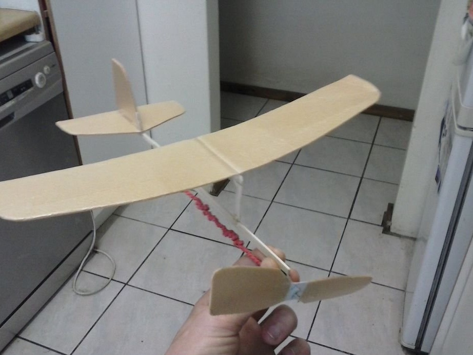
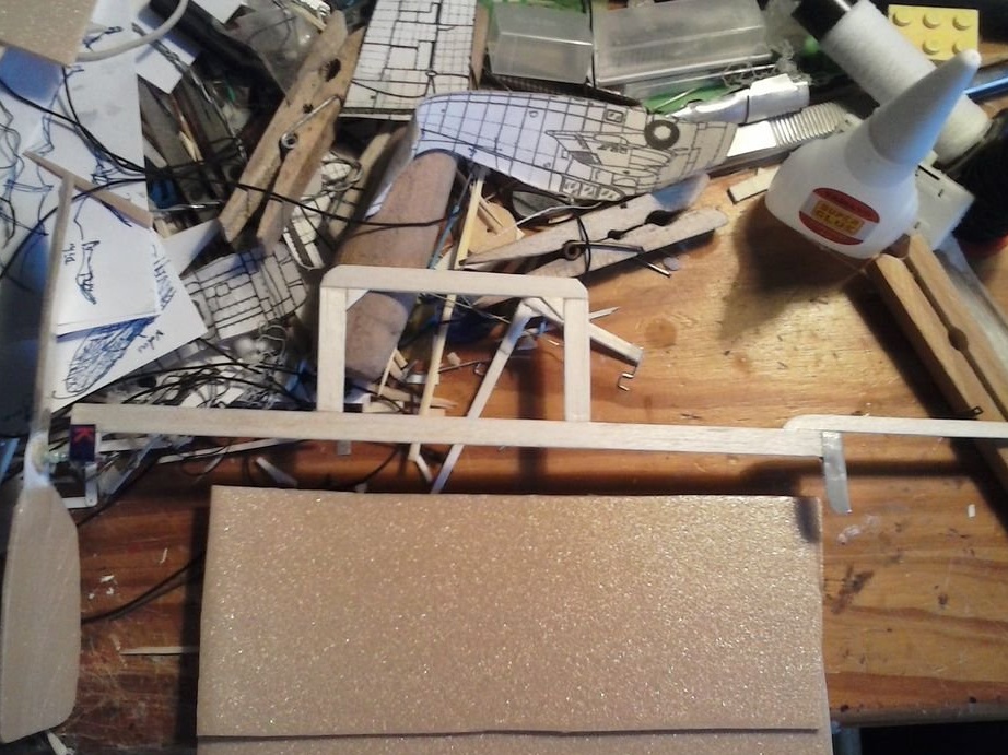
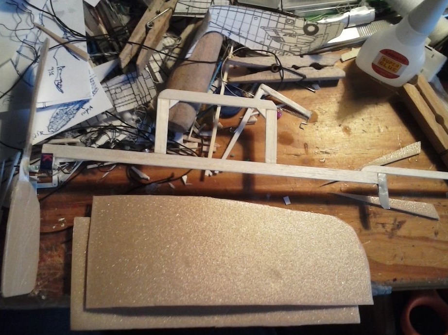
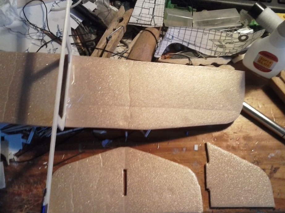
For wings, cut out two rectangles of foam, each in a ratio of about 1: 2.5 (I have 60 x 160 mm). The length of the rectangle should be equal to ¾ of the length of the main fuselage beam. Look at the third photo. You can cut one rectangle, and already make a second one on it. The wings can be left rectangular, but the flight of the model will be more stable if the wings are cut, as shown in photo 4. Connect the two wings together with duct tape (photo 5). They should be glued over the support (photo 6).
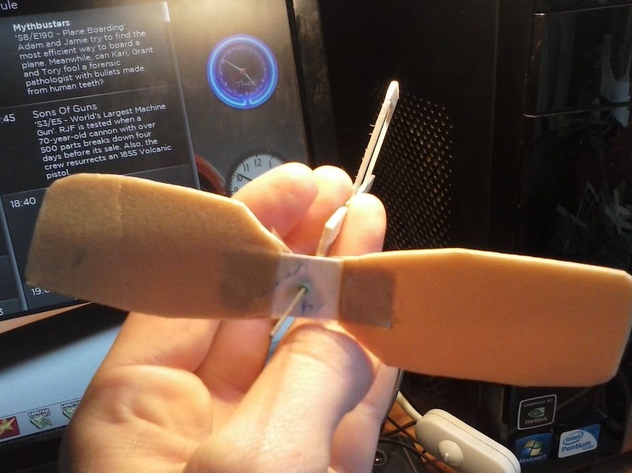
A horizontal stabilizer should be made in the same way. The aspect ratio of the rectangle (both keels in the bill) is about 1: 1.5 (I have 55 x 13 mm), the length is ¾ the length of one of the wings. To cut a symmetrical keel, you can fold the rectangle in half, and cut one contour.
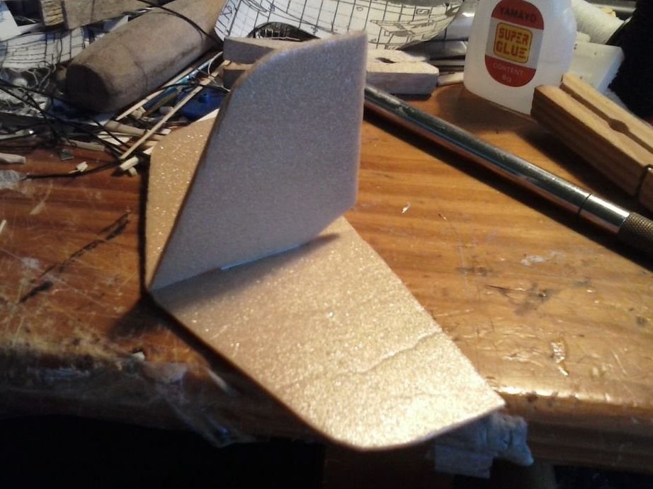
For a vertical stabilizer or “keel”, make one more such “half” (as you just cut) and cut the bottom edge, as shown in photo 7, so that you can insert it into the horizontal stabilizer (in which you need to make a cut, as shown in same photo). Photo 8 shows the assembled keel.
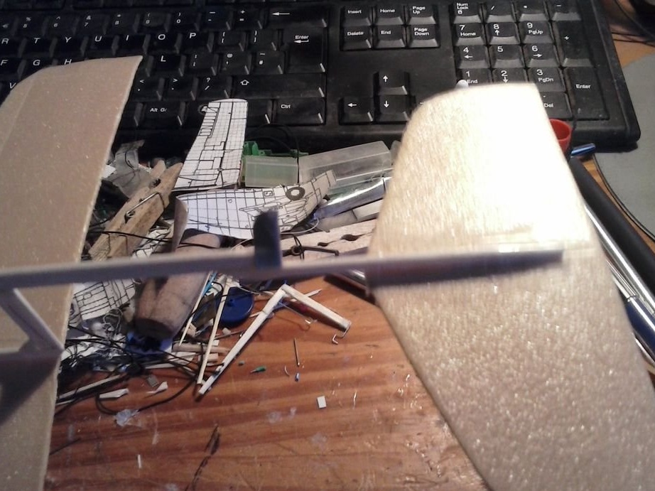
When the parts of the keel are fastened, it must be glued with tape to the top of the tail boom.
Pull the gum between the front and tail hooks and spin the propeller in the opposite direction, as far as possible without slipping the gum. Release the propeller and see how it rotates during the test flight. Correct the parts of the model so that it flies without problems. It is better not to launch the aircraft in a too crowded or cluttered place. If used improperly, you can injure others!
Pleasant flight!