
For the third year now, when Hackaday is hosting the next conference, it follows a good tradition: it distributes badges to the participants, which at the same time are quite powerful computing systems. Devices are included in the ticket price. They are produced in industrial small series, but are open hardware, which means that everyone who can’t get to the conference can, if they have the desire and the ability to make themselves the same badge as homemade do it yourself. This time the development team is quite large: these are authors under the nicknames Lutetium, Aleksandar Bradic, Mike Szczys, Sophi Kravitz, Mike Walters, Sprite_tm, Elliot Williams, de∫hipu, Kumar Abhishek, Piotr Esden-Tempski, Voja Antonic, Zapp, Roger, Hyr0n, Sylvain Munaut, and Sean Cross. And yes, Voya Antonich is again the same one, the developer of the now vintage, and once-new Galaksija home computer.
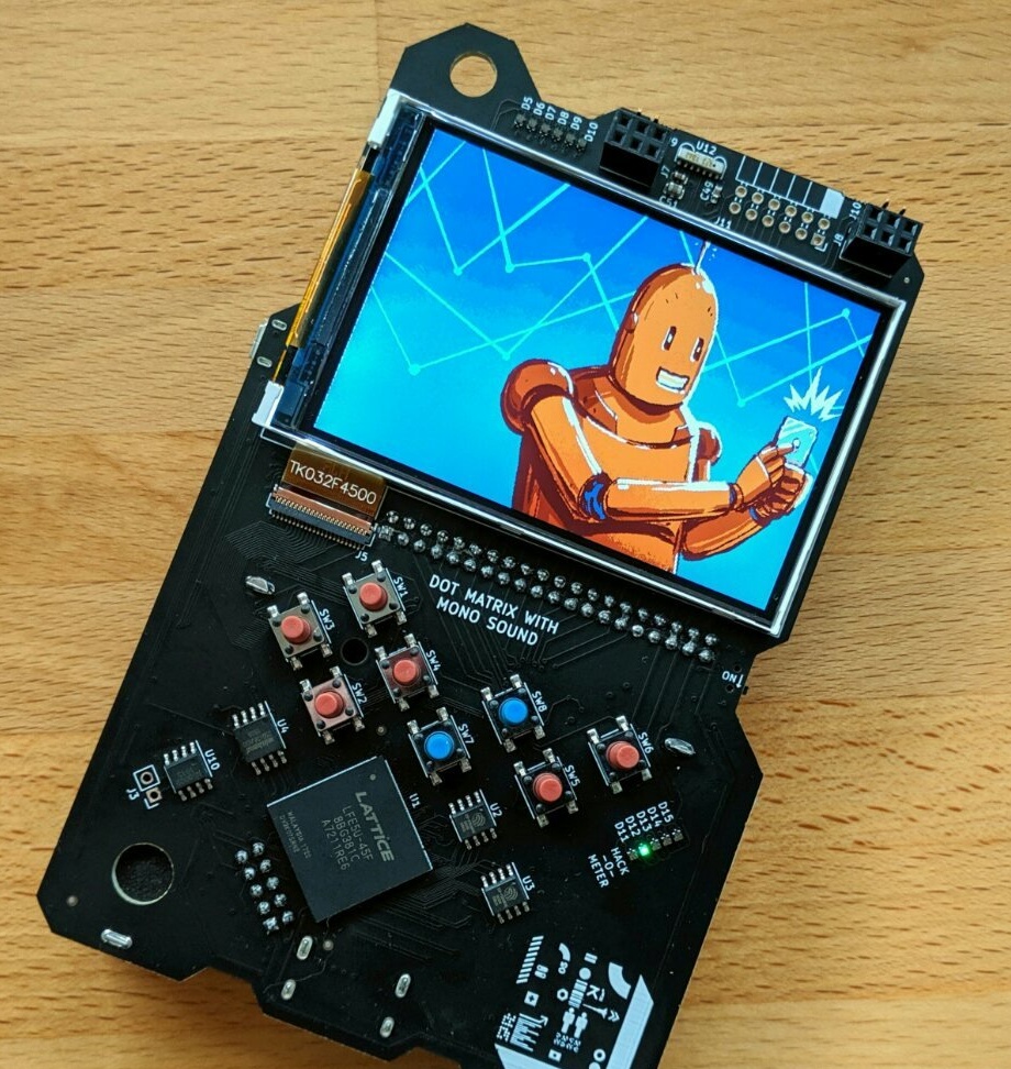
If in previous times the badge was made in a form factor similar to Cybiko or a QWERTY keyboard phone like Nokia Asha 200, and it could run the Z80 emulator, CP / M operating system and Basic language interpreter, now it looks more like a pocket one a game console like Game Boy. And even allows you to connect 40-pin cartridges. And this time it was made on the FPGA Lattice LFE5U-45F.
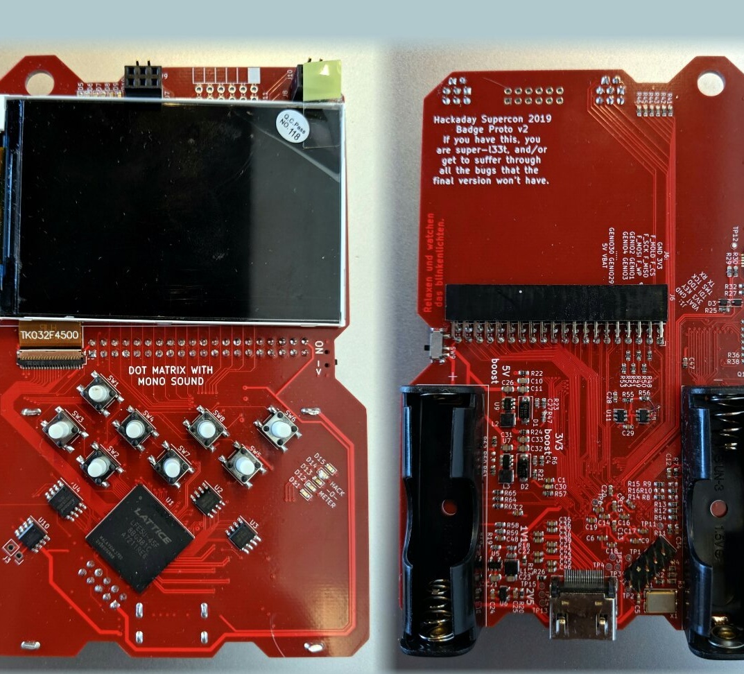
Repeating the device should begin with the hardware. The first thing to do is download all the files from here and install the necessary software, first of all - KiCad. Open the diagram in it (hadbadge2019.sch file) and purchase all the components included in it, having previously read the notes (hadbadge2019-bom-notes.txt file). Open the circuit board drawing (hadbadge2019.kicad_pcb file) and export to Gerber format. Order the manufacture of a board in a company of the appropriate profile. Even if you are fluent in LUT, in this case it will not help. In the workshop for repairing smartphones, order mounting on a component board in BGA cases. You easily solder all other components yourself, focusing on the photo below, remembering that some components, for example, LEDs, are polar.
In the FPGA, you need to fill the bootloader with the programmer by downloading all the files necessary for this from here. After that, all further interaction of your PC with the board will occur via USB. To fully revive FPGAs, you need to download the toolkit from here, and the code for the implementation on the FPGA of the RISC-V processor and interaction with peripheral devices is from here. Compile and fill in the code.
After that, the board will be defined as a regular flash drive, and it will be possible to put files with the programs intended for it on it. The program cards stored in the memory can be selected using the buttons through the on-screen menu.
The cartridge is optional. This is a very simple board that can be done by LUT, or even on perfboard. Below is a diagram of the cartridge and a picture of its board:
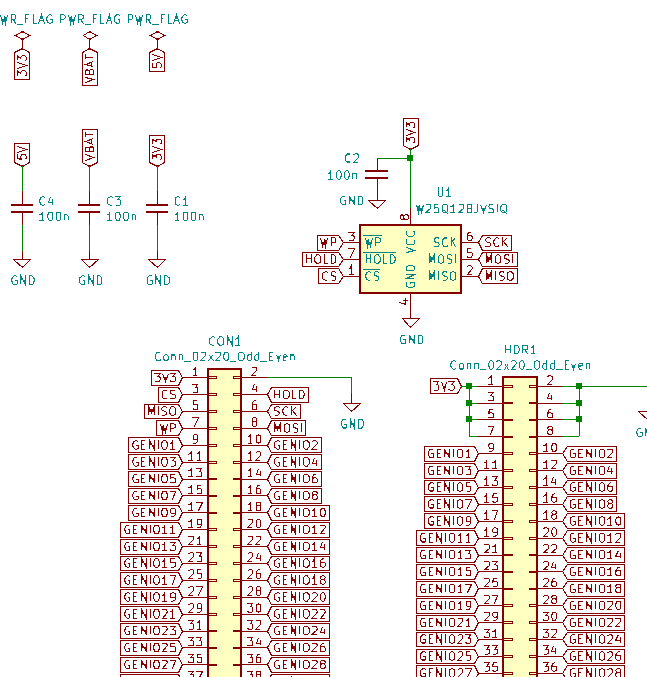
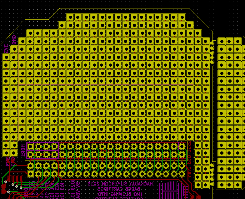
You can install a flash memory chip on the cartridge, and then when it is installed, loading from it will start automatically when it is turned on. There are also platforms for connecting various peripherals on the cartridge board. Files needed to repeat the cartridge are hereand KiCad, if you repeated the badge itself, you already have it.
If you are not a programmer, then you are all set. You can take examples here and here and experiment. If you decide to write any badge software yourself, the developers introduce everyone to the methods of contacting their user programs to the periphery.
The button names consist of the word BUTTON, an underscore, and one of the following words: UP, DOWN, LEFT, RIGHT, A, B, SELECT, START.
Example code for polling a button:
if ((MISC_REG (MISC_BTN_REG) & BUTTON_RIGHT)) {
    // Do something when right button is pressed.
}
Example code for reading a timer reading up at a frequency of 60 Hz:
uint32_t counter60hz (void) {
    return GFX_REG (GFX_VBLCTR_REG);
}
Example code for reading a number from a hardware random number generator:
MISC_REG (MISC_RNG_REG)Example code for LED control:
MISC_REG (MISC_LED_REG) = 0xF;The most complete information on the graphics engine of the device is given in this file. Graphics - tile and sprite (like on NES). The image on the screen consists of four layers (listed from top to bottom): a sprite layer, layer B, layer A and background layer. Sets of tiles, each of which has a total resolution of 256x512 pixels, consist of square tiles with a side of 16 pixels. The palette is 16-bit.
The layer holds 64x64 tiles, but a window of 30x20 tiles is visible on the screen. When a layer is selected, all changes in it become visible immediately. The window can be moved smoothly relative to the layer.
Layers with tiles can be scaled and distorted, the current examples are given in the main.c file. Work with the sprite layer has not yet been implemented, it will be made closer to the conference. The examples will then be placed in the same file.
Here's a team of developers got an interesting design. Someone will say that in previous times with a QWERTY keyboard and BASIC it was more interesting, but retrocomputers remember both worlds - and home computers, and consoles. And probably that's right.