» Topics » Advice »Flashlight, working from the heat of the hand (on Peltier elements)

Flashlight, working from the heat of the hand (on Peltier elements)


Greetings dear lovers homemade and young (and maybe not so already) electronic engineers, as well as lovers of alternative energy. In this article I will tell you how to make the simplest converter of heat into electrical energy. It is even more true to say not heat, but temperature differences. If you still do not know what the “Seebeck effect” and Peltier elements are, then before reading the article I recommend reading the relevant materials on Wikipedia. Today I’ll just tell and show how in practice all this can be applied. There are quite a lot of materials on the Internet on this topic, but I constantly did not like either the performance or the incomplete explanation of the “topic”. My homemade product is very simple, so it can be repeated by almost anyone who has ever held a soldering iron in their hands and knows how to understand circuits and understand radio components (although I will explain everything for completely newbies).

And before starting to read the article, I recommend watching a video with a demonstration, and a detailed assembly process.


And so, here is the scheme that we have to collect.

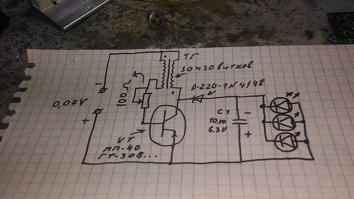
As you can see, it is necessary to apply only about 0.07V to the input for the circuit to work. It is just such a low voltage that our Peltier element will give out.

To build, we need the following:
- 1 Peltier element
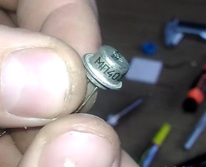
- Germanium transistor mp 40
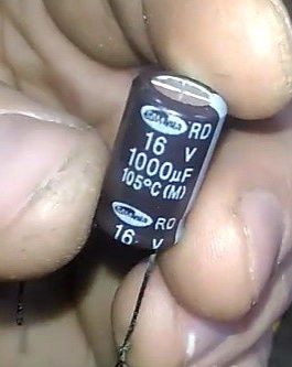
- electrolytic capacitor 16V 1000mkF
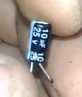
- electrolytic capacitor 25V 10mkF
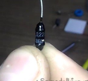
- rectifier diode D220 (although you can use any other with low losses)
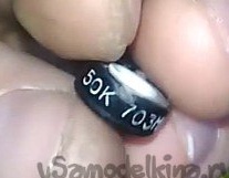
- tuning resistor (from 1kΩ, I use at 50kΩ)
- Light-emitting diode
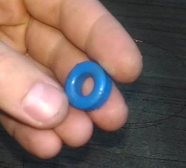
- ferrite ring
- varnished wire 0.25 mm
- radiator (optional, for more efficient cooling)

And:
- soldering iron and accessories (flux, tin)
- knife (for stripping wire)
- glue (optional)


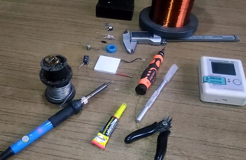
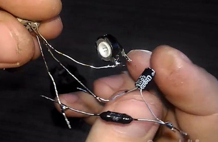
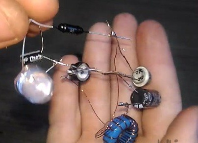
Here is an image of the components that will be required.


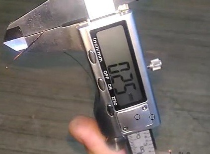
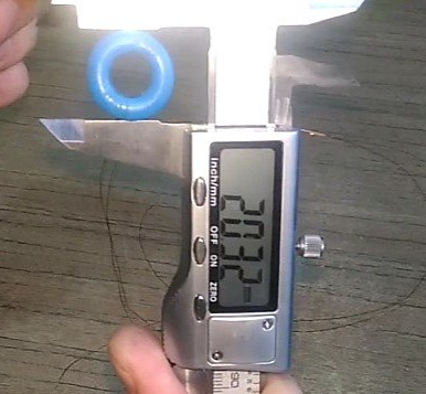
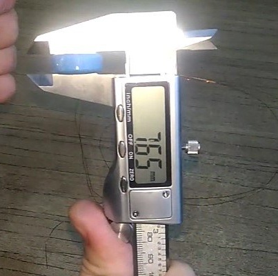
First, measure and cut 2 pieces of 50 cm of varnished wire 0.25 mm.
[center]

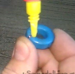
Next, we prepare a ferrite ring. We immediately pass 2 pieces of wire, make 1 turn and fix the winding with glue. I also recommend that you immediately sign the beginning and end of the windings (in any way convenient for you).

After evenly wind the wire, periodically fixing with glue.


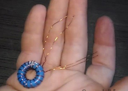
After completing this step, something like this should come out.

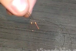
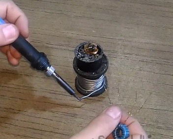
Next, we clean the ends of the windings, and then tin them.


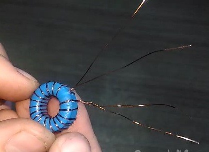
After this, it is necessary to find the beginning of one, and the end of the other winding (for this it was necessary to somehow designate them), then twist them and solder them together.

After these actions, 3 ends should come out of the ring (there were 4, 2 twisted together).

With this stage sorted out, it was the turn of assembling the main parts of the circuit.

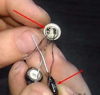
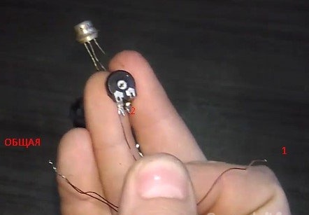
We take our transistor, and immediately sign where what is located (collector, emitter, base)

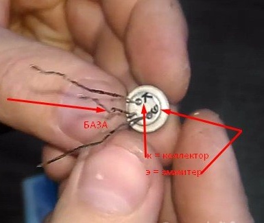
If it is positioned as shown in the figure, the collector will be on the left, the base in the center, the emitter on the right.
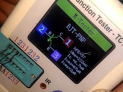
If anyone is interested, here are some characteristics of a transistor.


We need to solder our trimming resistor to the base (central leg) of the transistor.

Next, we take our diode in the hand, and determine its anode (triangle) and cathode (arrow).

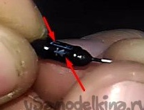
Now solder the diode with the cathode side (arrows) to the collector of the transistor.

Then we prepare the capacitor for 10 μF which, and solder it “minus” to the output of the diode.

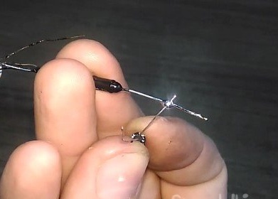
And the “plus” of this capacitor is the emitter of the transistor.

Thus we get "this."

It was the turn of the LED. We solder it parallel to the capacitor and according to its polarity. That is, the minus of the LED is soldered after the diode, and plus to the emitter.


It is time to connect the ferrite ring to what we just soldered.
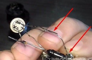
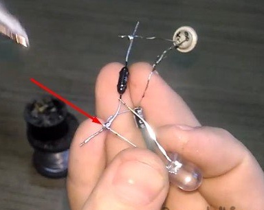
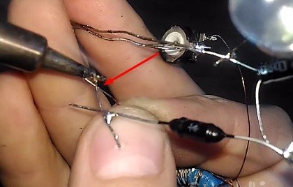
As you probably remember, 1 of the outputs of the tuning resistor was soldered to the base of the transistor, well, and 2 of the output must be soldered to one of the ends of the winding on the ferrite ring (the end that is not twisted!).

And the remaining free winding (again, which is not common!) Is soldered to the collector (above the diode!)

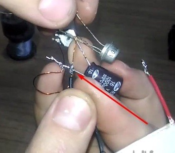
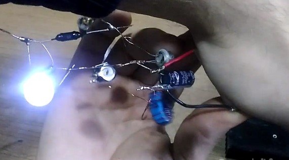
We get something like that.

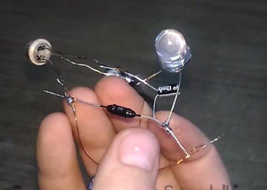
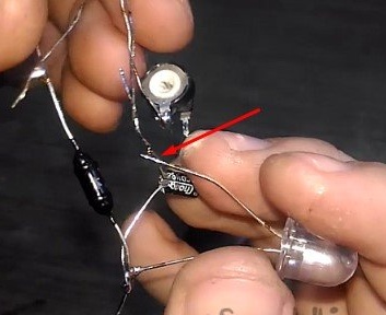
Next, we take the remaining capacitor (at 1000 μF), and solder its “plus” to the emitter, and the “minus” is connected to the same double winding of the ferrite ring.


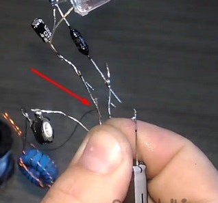
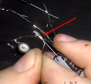
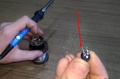
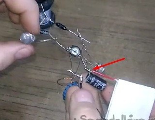
On this, the circuit can be considered practically assembled, it remains only to solder the element itself.

To do this, the black wire (minus) is soldered to the minus of the capacitor (it is clear that the one at 1000 μF), and plus to the plus of the same conder. That is parallel to him.


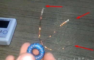
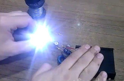
ALL! At this stage, the assembly is complete! What now is needed for this circuit to work? Nothing, just put your hand on one of the sides of the element and it will work.

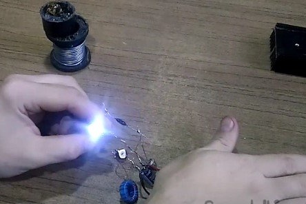
But for a more efficient conversion, more efficient cooling of the reverse side of the Peltier is also necessary. For this, a radiator is used.


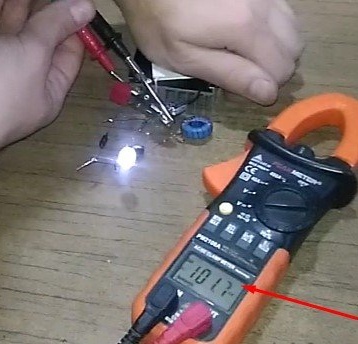
By the way, the circuit "starts" from a voltage of only 100mV!

Well, now I will express my opinion a little about this. The topic of alternative energy is developing more and more in the world, solar, wind and many others. But the topic of thermoelectric converters is raised quite rarely, although this is a very effective way of converting energy. The temperature difference is found everywhere, inside and outside the room, at different levels of the layers of soil, air and so on!

Our world is immersed in a huge ocean of energy, we fly in infinite space at an incomprehensible speed. Everything revolves around, moves - all energy. We have a daunting task - to find ways to extract this energy. Then, extracting it from this inexhaustible source, humanity will move forward with giant steps.
~ Nikola Tesla

Suitable for topic

Related topics

Add a comment

    • smilesmilesxaxaokdontknowyahoonea
      bossscratchfoolyesyes-yesaggressivesecret
      sorrydancedance2dance3pardonhelpdrinks
      stopfriendsgoodgoodgoodwhistleswoontongue
      smokeclappingcraydeclarederisivedon-t_mentiondownload
      heatirefullaugh1mdameetingmoskingnegative
      not_ipopcornpunishreadscarescaressearch
      tauntthank_youthisto_clueumnikacuteagree
      badbeeeblack_eyeblum3blushboastboredom
      censoredpleasantrysecret2threatenvictoryyusun_bespectacled
      shokrespektlolprevedwelcomekrutoyya_za
      ya_dobryihelperne_huliganne_othodifludbanclose
26 comments
But they found an error in the circuit.

There was a description, copied somewhere, but I can not find where. In your own words: when starting up on the secondary side, the voltage is rectified by the MVR3545 diode assembly (what the hell is a 35 amp diode?), From the other end of the winding it is fed to capacitors C11 and C13, and from them to the microcircuit, driver and output stage, i.e. Self-charging occurs and no battery is needed.
Quote: R555
Not a fig yourself! In this circuit, it smacks of returning energy back to the battery ...

They claim that the battery is needed only to start, and on the diagram is a button, not a toggle switch.
Not a fig yourself! In this circuit, it smacks of returning energy back to the battery.
I did something similar, but they told me that the Perpetual motion machine is not possible. I listened and quit this venture.
A familiar alternativeist showed me a flashlight, where he drives energy in a circle.
Curiously, I will try to delve into the scheme for a future dream.
Stumbled on the Internet - here guys make flashlights! xaxa

Later scheme


I don’t know if links can be inserted, maybe someone from ours will repeat ...
(https://realstrannik.com/forum/akula/661-akula-0083)
brackets must be removed
I don’t know, like the bourgeoisie, but we have riveted transistors like that. We stamped the batch and passed through the installation and watched which transistor fits into the tolerances.

I worked a bit before the army in the diode workshop. (I don’t remember which ones. In the glass). I did the holder myself - for specials. two different types of wire were welded by contact method and cut. (I remember it was platinum and also, some kind of bimetallic ...). So .. The holder surrendered to the Quality Department in boxes of 50,000 pieces approximately. And his quality depended on the sharpness of the knife in the machine. Payment was piecework. Top grade was valued more, then another first and second. Those. It was possible to grind the knife every hour, and only do the highest ... But not enough!)))) Therefore, they did a lot - the first boxes went to the top and so on ... So, the top grade went to the "defense", the first - for export (our diode, as they said, was in any Japanese tape recorder, because it was made by two factories in the world, and one of them in the USA, the other - our Tsvetotron). And the second grade - "will go to the Union")))) ... There was also a third ... This is - on the circles of young hams, in schools and more ...)))
Yeah. and if you look closely, there are rhombic, pentagonal star and VP, OS stamps. xaxa

I have such semiconductors, somewhere in the early 60's, they are in some of my products and still work. Amazing Able to do then.
Quote: R555
I ... It is necessary to add a block to this circuit so that you can insert different transistors without soldering ....

In the photo with a red LED under the transistor, the edge of the socket is visible.
Such transistors came across - it’s beautiful, shiny, and the top is smeared with paint and clumsy KT8 ** stamp. And under the paint - 2T8 **, PZ did not pass.
R555
there are transistors in which the noise is much less than what is written in the manual and the label on the transistor itself!
In reference books, as a rule, limit parameters are indicated!
Кш - Transistor noise figure: no more ** dB at a frequency of ** MHz;
I will add about the difference between the parameters of a real transistor from the reference data.

When he was very young, he presented at the exhibition a device for selecting transistors by noise (for the military). That is, from the finished batch of transistors produced by the plant, the samples with the smallest noise were selected.

This meter was a steel coffin with 2 handles on each side, we barely unloaded it from the car and brought it to the exhibition xaxa

And this box showed that there are transistors whose noise is much less than what is written in the manual and the label on the transistor itself! good

The saturation voltage and gain can also differ for the better from the declared ones.

But it is not necessary to make a coffin, it is enough to put a block, and it is better to bring out 3 crocodiles on the wiring.

And you can experiment boss
This is what I thought. It is necessary to add a block to this circuit so that you can insert different transistors without soldering.

I had something to do with transistor manufacturing.

I don’t know, like the bourgeoisie, but we have riveted transistors like that. We stamped the batch and passed through the installation and watched which transistor fits into the tolerances. On appropriate set appropriate

marking. So from here such a mass of letters went on the same transistor.

Well, most went straight to the trash. xaxa

Therefore, it is necessary to try different transistors in this circuit, quickly transferring them. In the reference book give averaged data.
He made a converter based on the circuit of S. Belyaev (Converter for powering a digital multimeter. Radio 2003) There are 2 transistors. It was a long time ago. Something did not like ... In my opinion there was a low efficiency (and noise?)
... But the problem is to open the mosfet you need to apply to the shutter of volt 3, it seems ....
Yes, at least 10, you just need more turns in the winding of the OS.
And yes, they don’t have such a thing as saturation voltage, they have a drain-source resistance, miliomas.
Here I was thinking about the use of mosfets, because their saturation voltage is generally insignificant, in any case, less than 50 mV. And the gate’s current is negligible, not like the base current of the bipolar. I wish they could stir up this miracle generator. But the problem is to open the mosfet you need to apply to the shutter of volt 3, it seems.

I have some kind of brilliant idea spinning, but I just can’t catch up swoon
I remembered KT863, KT630 ​​with their U-ke of us 300 mV. And about the turns at MIT-4 ... well, it’s inconvenient to rewind it dance
Yes, MP42B was the best. Even less common MP20, MP21 can be tried, with the number of turns and their ratio play.
And from Shotka, what do we have?
As for the capacitors, I agree. MP16 is the ancestor of MP42, i.e. It is considered to be pulsed, in the photo it is, MP40 is worse. In general, I wanted to try on a fieldwork.
So - is another matter. To start the BG, 70 mV is not enough, then, after starting, you can slightly lower the voltage. To improve performance, you need to shunt the base resistor with a capacitor, and to increase reliability, turn on a small resistor in series with the trimmer. From RF transistors in this circuit is unlikely to be better. It is necessary to take transistors with large h21e and small Uost. You can try those that are designed specifically for pulsed circuits.
At 98 mV (minimum) it starts and works, but only with red (the smallest voltage) and if it is work, then ... It’s a bit visible. Transistors MP40A, MP16B, HF have not tried. For a parallel pair of white runs 300, an acceptable glow of 700 mV.
Of course. D220 - silicon, where does the small drop come from?
Has a BG from 70 mV started? Or started up at a higher voltage, and then worked when it was reduced to 70 mV?
I take off my objections, sorry smiles First: with zeros it is necessary to be more careful, not 70 mV, but at least an order of magnitude more gives Peltier. Second: soldered, here is the picture.

But for a real glow you need more voltage [center]
I read and want to say that the MP40 transistor will not work from 0.07V. I did so much of them ... Yes, the author writes that it is necessary to use the D220 diode with a small voltage drop. Since when does he have a small voltage drop? Here is D310, D311, another thing.
"... As you can see, it is necessary to supply only about 0.07V for the circuit to work ..."
0.07 V is 70 mV. yes
"... By the way, the circuit" starts "from a voltage of only 100mV! ..."
Unclear smiles fool
In the evening I’m not too lazy, I solder and see how many mV will work.
It seems like
Not "Flashlight, working from the heat of the hands", but a model showing the Peltier effect. ;)
A bunch of discrepancies between the list of elements, the scheme and the description surprised.
And the picture, allegedly depicting a UGO transistor, simply delighted.

We advise you to read:

Hand it for the smartphone ...