
The author of Instructables under the nickname mansurkamsur needed large LED arrays - 100x100 mm, despite the resolution of 8x8 pixels. Ready-made boards with this resolution come in various sizes, the maximum of which is 60x60 mm. I had to make custom matrices do it yourself.
Homemade executed on the MAX7219 chip, so it is fully compatible with existing programs for Arduino and other platforms that control similar off-the-shelf matrices. According to the scheme, it also does not differ from them, only the LEDs are larger. And chaining, like shift registers, allows no worse. But, unlike the shift register display, the indication here is dynamic.
The device diagram is also standard:
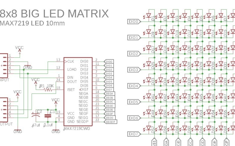
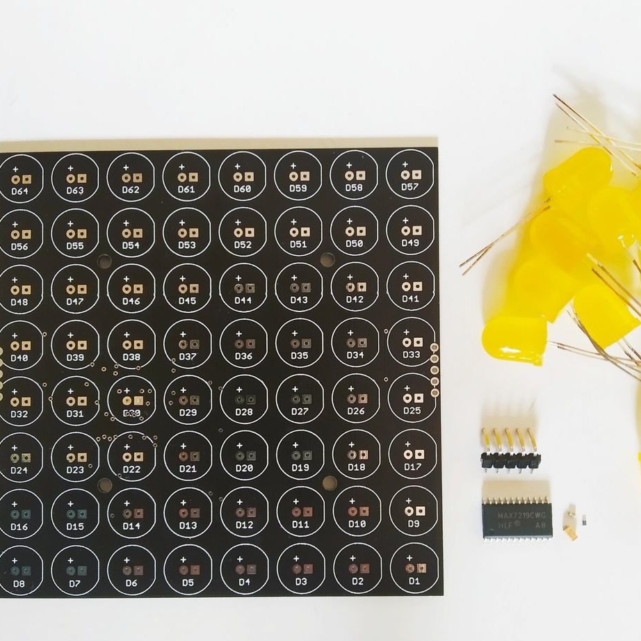
Large LEDs will be needed - with a diameter of 10 mm. If you do not find such, you can take the usual, 5 mm, also with flexible leads. But then the step between them will be very large. All other components, including driver chip - vice versa, miniature and SMD. This also applies to the polar capacitor, which is taken not electrolytic, but tantalum. It is not recommended to use it, since such capacitors light up when accidentally reversed and / or overvoltage. Literally. By the fire. It is better to solder a conventional electrolytic capacitor with leads to the same pads. Anyway, the board is big.
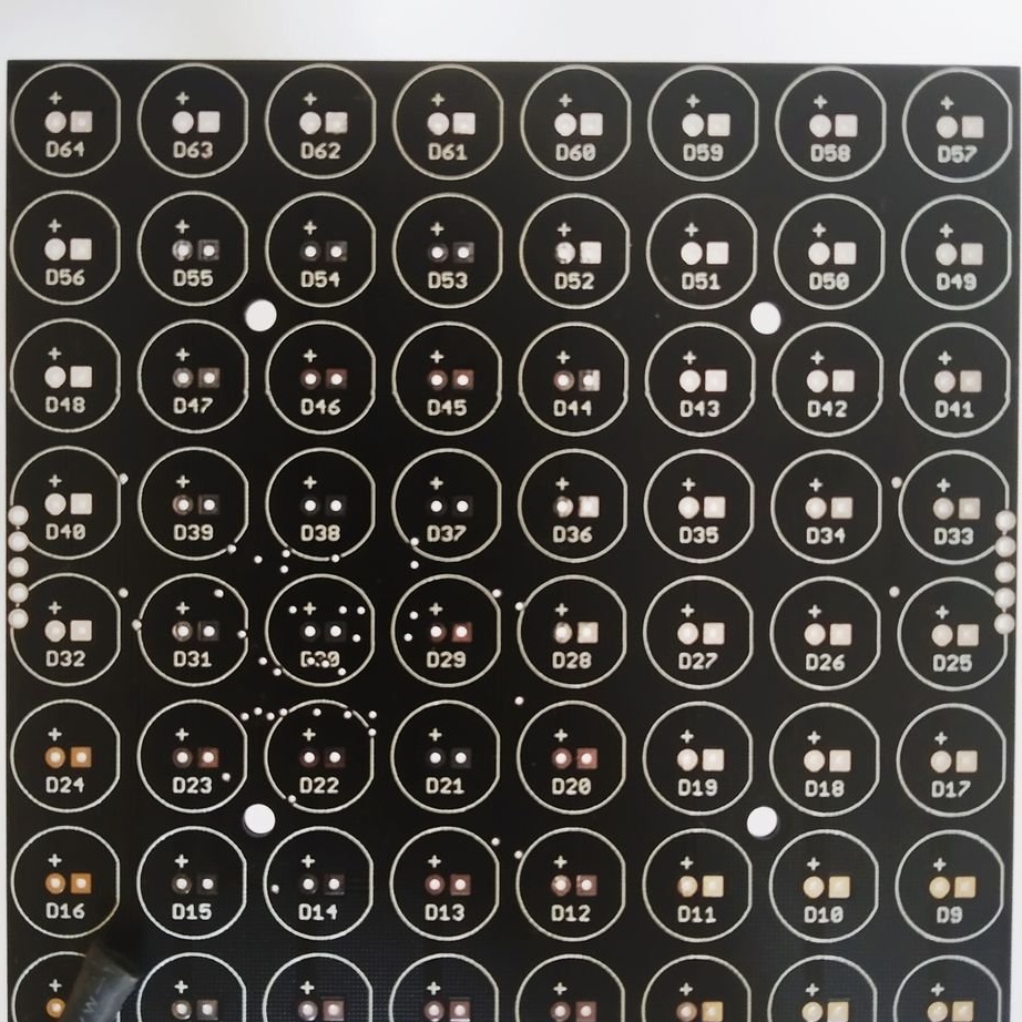
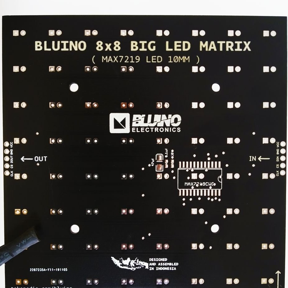
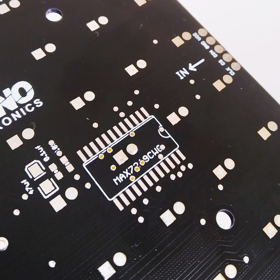
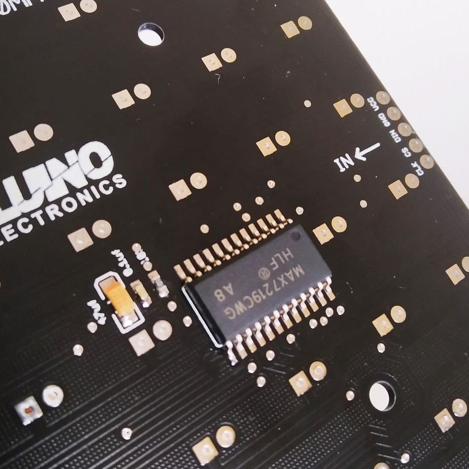
Master uploads Gerber format files for making a board here licensed under CC-BY-SA. To download them, the simplest registration is required. There is nothing complicated in the manufacture of the board, it is possible and LUTom. And with a certain dexterity - and on perfboard. But the master decides to order the boards (he needs several modules) right there (from another manufacturer it is also possible). And so they come, consider any of them from both sides:
And the components come:
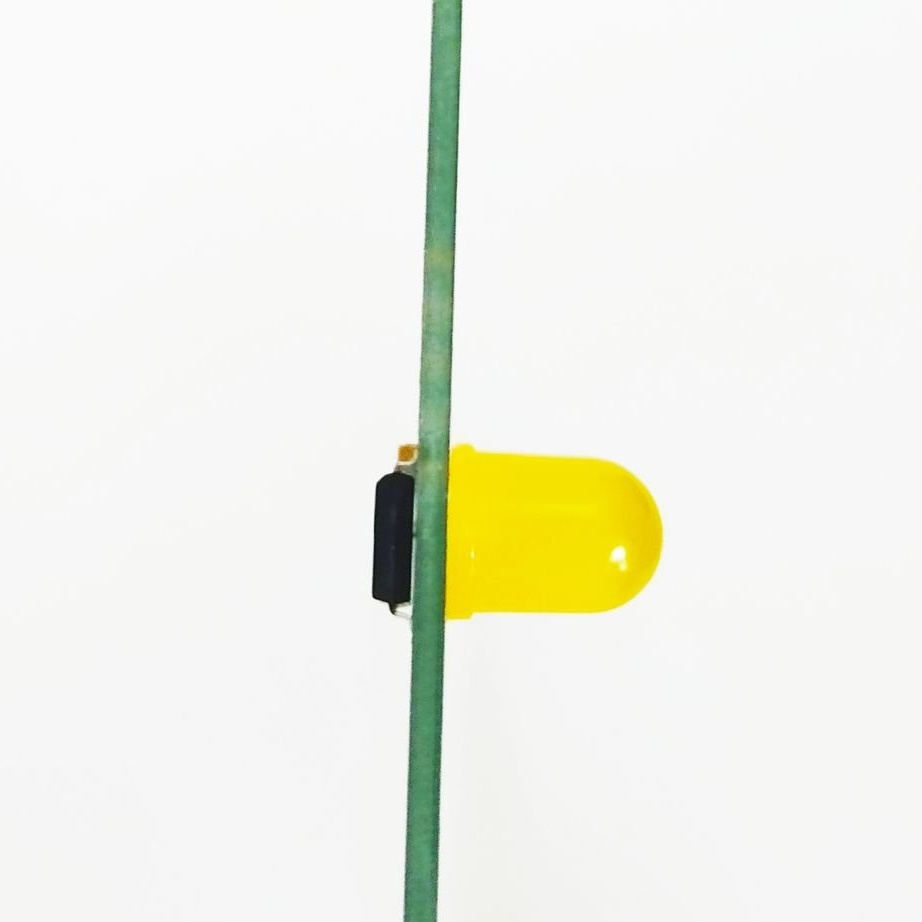
A feature of the device is the location of the driver chip on top of the solder points of the LED with the designation D30. Therefore, he first solders this LED, having bitten off the conclusions to such a length in advance that the microcircuit fits:
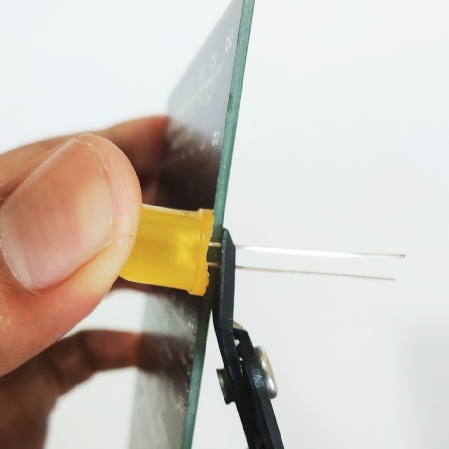
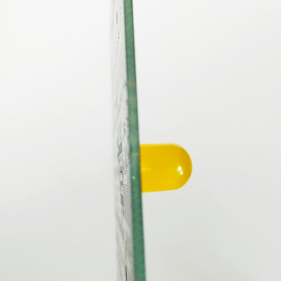
Due to the metallization of the holes, this focus passes, and the “legs” on the back side of the board do not protrude. If the board is made by LUT, you will have to bite off after soldering, and the LEDs themselves - not solder right next to the board to solder on both sides. The role of jumpers will play their conclusions.And the conclusions of the microcircuit will have to be slightly bent so that it can be slightly raised above the solder points of the LED. But the master solders the chip itself:
And behind it - and the rest of the LEDs:
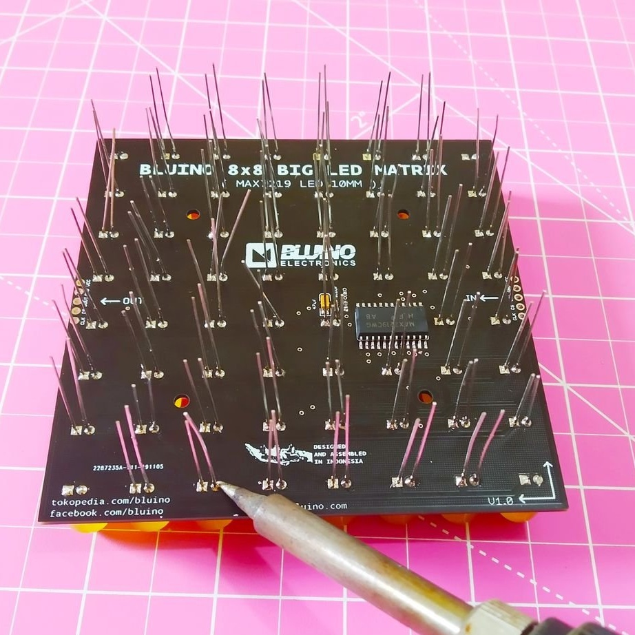
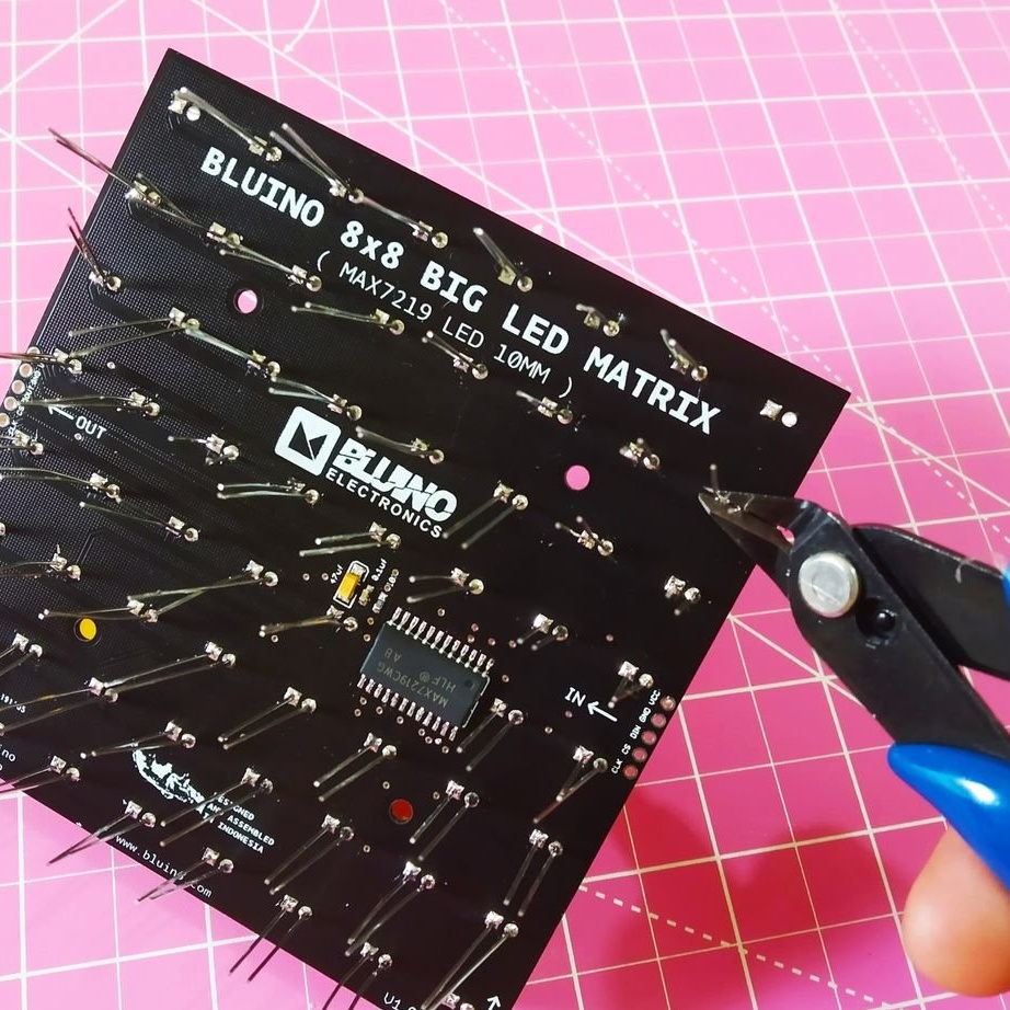
These LEDs bite off the conclusions after soldering:
And passive components. If you still decide to use a tantalum capacitor, check the polarity ten times. For LEDs, it is enough once, for tantalum - all ten. And check the polarity of connecting the power to the finished board as many times before turning it on. This is a fire safety issue. But it is better, of course, to install an ordinary electrolytic capacitor instead of tantalum. He, of course, is also afraid of polarity reversal, but at least there will be no fire.
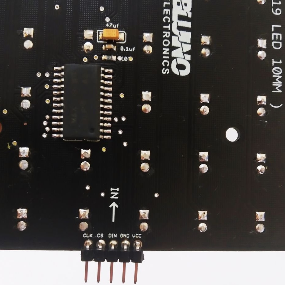
Finally, the master solders the comb from the input side into the board. Now you can connect a connector to it and apply power and control signals. To connect the matrices into a chain, it is necessary to solder the input comb of the next board to the output platforms of the previous ones. All boards must be fixed on some basis, since the strength of rations alone is not enough.
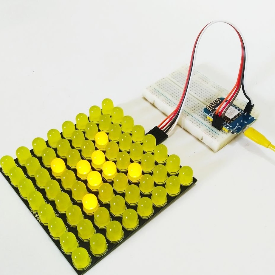
Finally, the wizard tests the module:
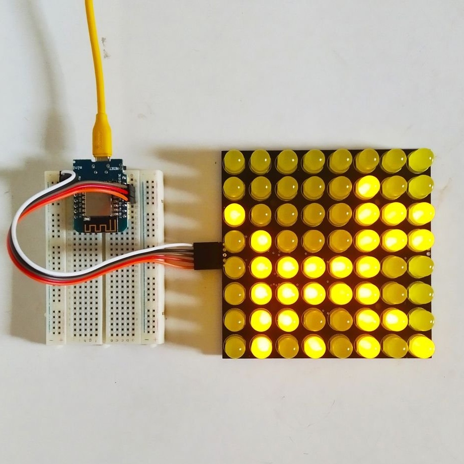
To do this, he uses the Wemos D1 board, since there is ready-made software for it that manages such matrices. Arduino and other platforms are also suitable, for some of them you will have to write software yourself. Having made the right number of devices, you can make a display of the required size and resolution from them.