» Fixtures » Machine tools »Drilling machine - rhomboid

Drilling machine - rhomboid

Drilling machine - rhomboid

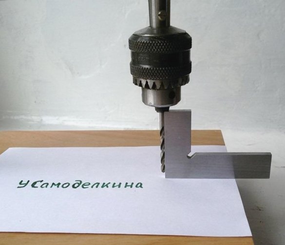
It is proposed to make a small drilling machine of a very simple design. For its manufacture, the pattern parts will not be required - precise guides, rolling bearings, moving mechanisms. If in your household there is a small instrument motor with a drill chuck on the shaft, then you can start work. We make the machine from improvised materials. Billets for components will not be difficult to find.

Design Features.
This machine is easy to manufacture, but has some limitations. Its design is designed for drilling holes up to 10 mm deep. The capabilities of the machine in drilling diameter and the material being processed depend on the characteristics (power, shaft rotation speed) of the electric motor used.

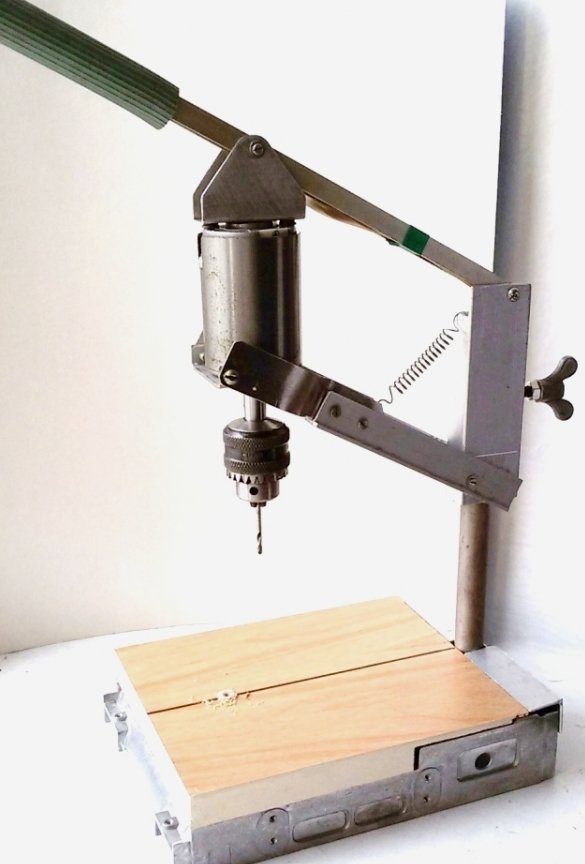
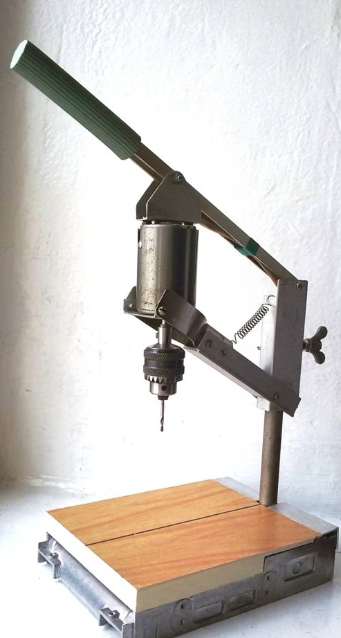
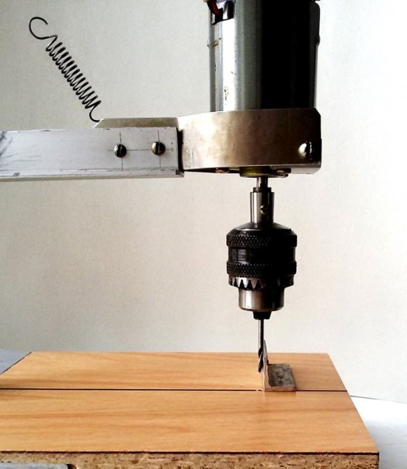
A limitation in drilling depth is associated with the design of the drill drive suspension. The device is based on a hinged parallelogram. Two vertical, equal in length and opposite links parallelogram, this is the electric motor and the base of the suspension. The remaining two equal and opposite links are the connecting elements. As you know, in this design, the opposite links will be parallel at any rotation of the links of the parallelogram. Therefore, the common axis of the electric motor and drill (in the exact manufacture of parallelogram elements) will always be parallel to the axis of the fixed stand and perpendicular to the machine table.

For reference, a rhomboid is a parallelogram in which adjacent sides have different lengths and the angles are not straight.

Setting up and working on the machine.
The position of the connecting links parallel to the table will be taken as the zero position. When machining a part on a machine, to increase accuracy, the location of these links should approach a horizontal position.

In this case, with the axial movement of the drill from +5 mm to -5 mm (10 mm stroke) from the zero position of the links, the radial offset of the drill (in the rhomboid plane) will be 0.08 mm. This amount of displacement will be at a link length of 150 mm. In practice, this displacement is imperceptible, and will not be critical for the tool and the hole being machined.

When drilling printed circuit boards, even with a brittle carbide tool with a diameter of 0.8 mm, the offset of the drill on the board with a thickness of 2 mm will be 0.003 mm (3 microns). Compare the given value with the offset and position of this drill when processing boards manually.
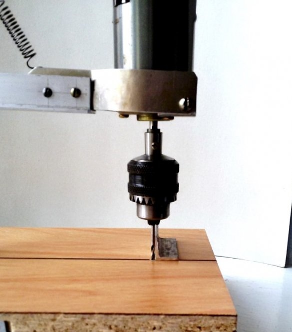
Setting the machine to the size of the part, in height, is carried out by quickly moving along the machine rack manually, the suspension base and fixing it with a thumb screw. The height of lifting and fixing the base of the suspension is visually determined by the risk of the zero position (plotted on the base of the suspension - the last photo) when touching the part with the tip of the drill. When drilling various boards with a thickness of 1 ... 3 mm, a readjustment in height is not required.

Additional design advantages.
The ability to install large-sized boards (with an increase in the overhang of the drill, the accuracy of drilling increases).
When releasing the handle, at the end of drilling, the motor with a drill under the action of the spring quickly goes up and back a considerable distance, freeing up the processing zone of the part.

In the highest position, you can conveniently quickly and safely change the drill.
I think that the above characteristics speak in favor of the manufacture of the proposed machine. The time spent on the manufacture of this machine design pays off in a good mood from the exclusion of breakdowns of expensive and scarce drills.

1. Applicable materials and details.
Electric motor and mechanical or collet chuck.
Pieces of a metal sheet with a thickness of 1.5 ... 2.0 mm.
Aluminum profile hire, pipe.

2. Making a table of a drilling machine.
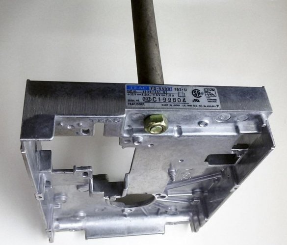
First of all, you need to decide on the table of the drilling machine. Its size, rigidity and strength will determine the accuracy and ease of use. There are many different table designs. In the given version of the machine, the case of the CD player, which has long been waiting for its secondary use, is used. Rectangular case with dimensions of 145 x 200 mm, cast from aluminum alloy. It has low weight, a rigid structure and flatness along the periphery of the lower part of the part, which gives good stability to the future product. In addition, this part requires virtually no additional processing. For these reasons, the casing was taken as the basis of the machine table.


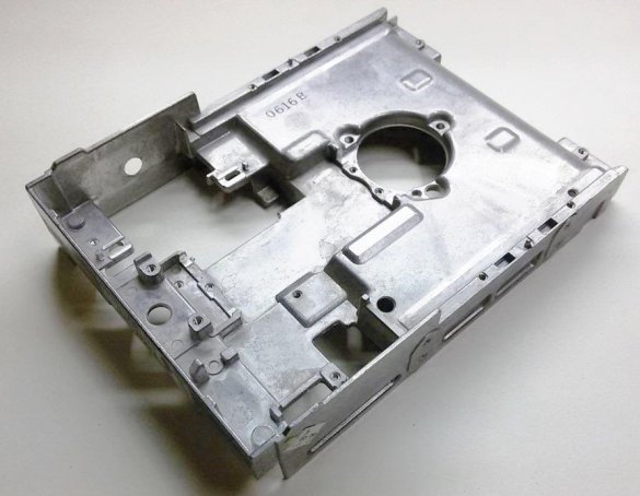
One of the short walls (in the photo on the left), in the middle, has a hole for the M8 bolt, which automatically determines the installation of the machine rack there.
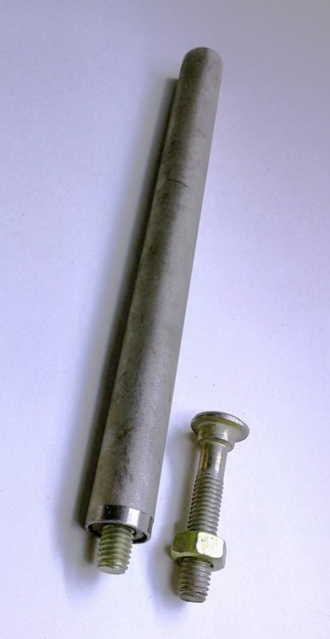
As a rack, you can use rolled metal or a pipe with a diameter of 18 ... 25 mm.
The structure under consideration used a thin-walled steel tube with a diameter of 18 mm, which made it possible to simplify the method of fixing it to the table.
We select a bolt with an M8 thread and a head, the diameter of which fits tightly into the hole in the tube (it may require some refinement of the diameter). Screw the nut onto the bolt and press them into the tube. The stand is ready. It remains to fix it on the table with a second nut.


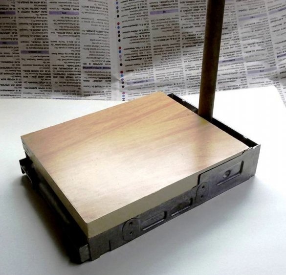
On the upper part of the table we fix the countertop cut from the laminated chipboard along the contour of the workpiece body. In this case, the machine stand will be additionally sandwiched between the wall of the housing and the countertop. In the future, on the free sides of the rack we fix the lining of an aluminum square. All this will provide the installed rack additional rigidity.

In the process, we check and, if necessary, adjust the perpendicularity of the machine stand to the table.


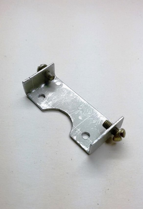
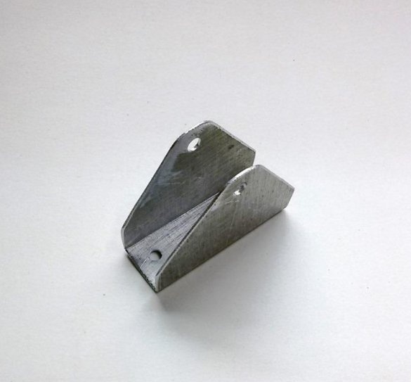
3. Making the base of the suspension.
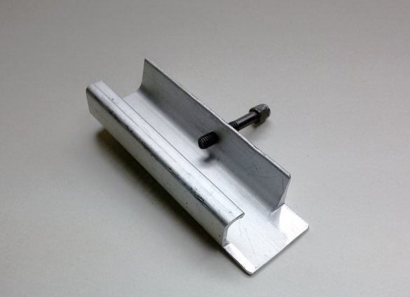
The suspension base is necessary to install the articulated parallelogram mechanism on the machine stand. It serves as an integral part of the rhomboid, fixes it on the rack, at the desired height and at a selected angle from the edge of the table. Shaped aluminum profile (18 x 40 mm), which previously served as a furniture door handle, was used as a blank for the suspension base.

In the middle of a section of the profile, about two electric motor lengths, we drill a hole and cut an M6 or M8 thread under the fastening screw. We check the reliability of the suspension base installation on the machine rack.


Manufacturing a mechanism for mounting an electric motor

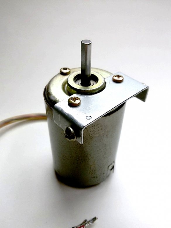
4. Lower engine mount.
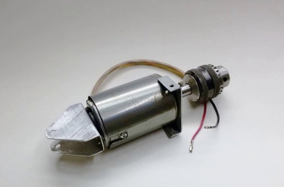
For the proposed drilling machine used a DC motor with permanent magnets DC 24V, 0.7A.


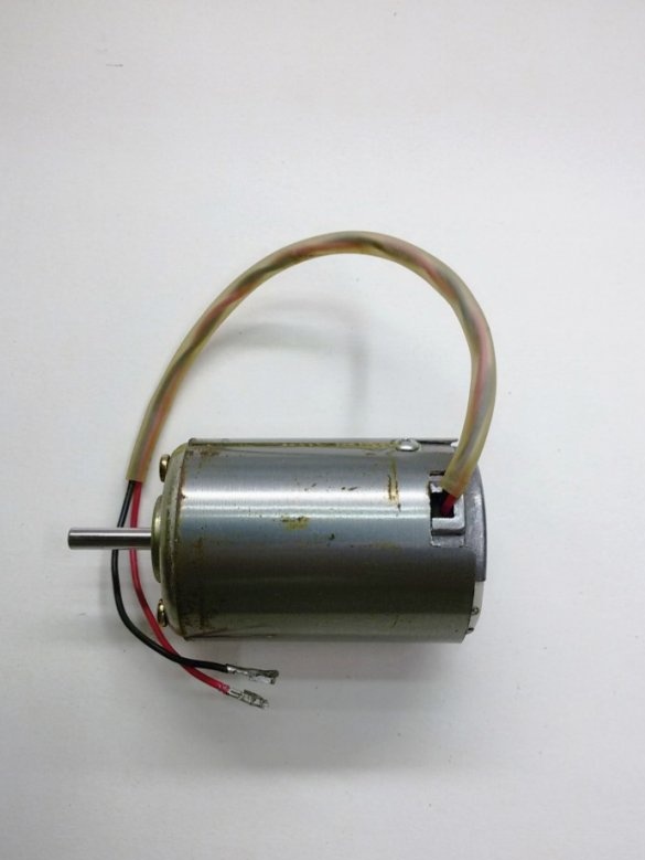
We begin the production of the articulated parallelogram with the main link, consisting of an electric motor and its fastening elements. The dimensions of the engine used may be different, as well as the location of the mounting holes. Therefore, the dimensions of the fasteners are not given.

From a steel sheet with a thickness of 1.5 ... 2.0 mm, we produce the lower engine mount. In the side shelves of the support, drill coaxial holes and cut the M4 thread into them. Install the engine mount with two standard screws.


5. The bottom link of the parallelogram.
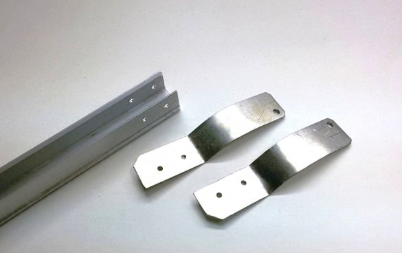
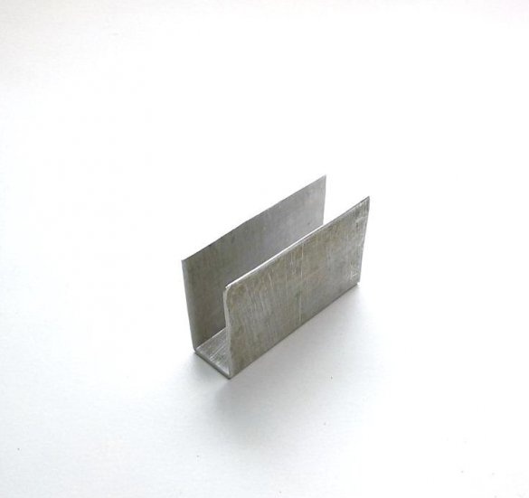
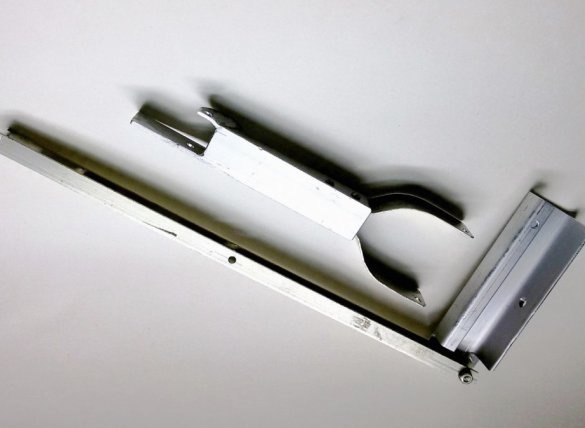
We will make the lower link of the parallelogram from the rolled aluminum available at hand. For example, in the proposed design, a U-shaped aluminum profile (20 x 20 mm) was used, which was previously used in the manufacture of windows.

To connect the lower link with the motor support, from a steel sheet with a thickness of 1.5 mm, we produce two mirror-made transition elements. They are rigidly connected to the link profile with two screws (rivets).


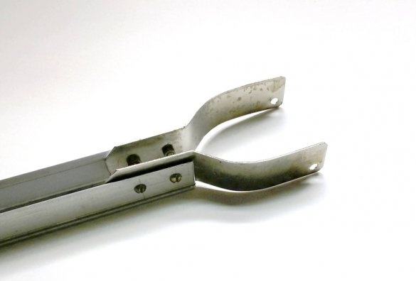
6. Lower link with motor support
The length of the lower link is determined by the size of the manufactured table. In this design, this length (the distance between the axes of the mounting holes) is defined as 150 mm. Mark the holes for connection to the base of the suspension and cut the profile to the desired size. If necessary, on the cut side of the profile, we form the width of the groove for a tight connection in width with the mating base of the suspension. We drill along the marking coaxial holes.


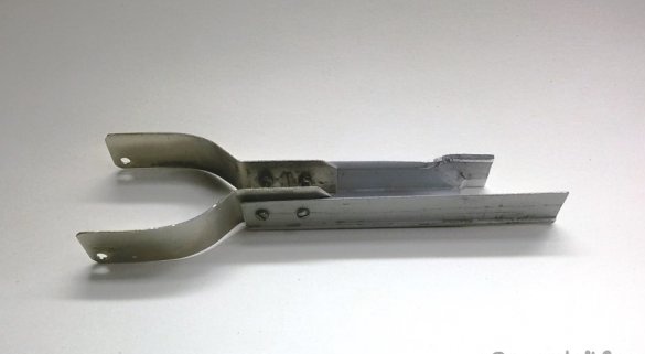
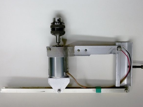
We assemble the lower link with the support of the electric motor. Using the M4 screws, we attach the lower link to the motor support, ensuring free rotation in the connection. The location of the hinge hole in the lower link, behind the engine, is dictated by the maximum possible increase in the length of the link, therefore, increasing the accuracy of processing.


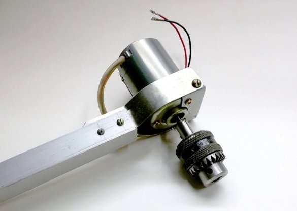
7. Upper engine mount.
From a steel or aluminum sheet with a thickness of 1.5 ... 2.0 mm, we produce the upper engine mount. The design of the part will depend on the location of the attachment points on the existing engine. Install the upper engine mount.


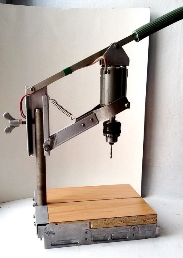
8. The top link of the parallelogram.
The upper link of the parallelogram is also made of rolled aluminum. For example, the proposed design used an H-shaped aluminum profile (12 x 16 mm). Mark the workpiece of the upper link. We transfer the distance between the axes of the mounting holes of the manufactured lower link on the workpiece of the upper link. Drill holes for marking. It is desirable to double the length of the workpiece of the upper link relative to the working size of the link. We will use the free end of the profile as a handle for feeding the drill, which will reduce the force of the hand by half. A piece of plastic tube can be put on this part of the workpiece.

The distance between the axes of the mounting holes and their location on the motor supports, we transfer to the suspension base. In other words, in the manufactured parallelogram, the lines connecting the axes of the mounting holes on the engine mounts and the suspension base must be equal and parallel.

To fulfill this condition, in the manufactured machine design, a part of the profile is cut out on the basis of the suspension (in the upper part).


9. Assembly of the articulated parallelogram - rhomboid.
We assemble the rhomboid, install it on a rack and check the mechanism in operation.


10. Mechanism accuracy control
perpendicular

for drills with a stroke of 10 mm


under load.
6
7.4
6.5

Add a comment

    • smilesmilesxaxaokdontknowyahoonea
      bossscratchfoolyesyes-yesaggressivesecret
      sorrydancedance2dance3pardonhelpdrinks
      stopfriendsgoodgoodgoodwhistleswoontongue
      smokeclappingcraydeclarederisivedon-t_mentiondownload
      heatirefullaugh1mdameetingmoskingnegative
      not_ipopcornpunishreadscarescaressearch
      tauntthank_youthisto_clueumnikacuteagree
      badbeeeblack_eyeblum3blushboastboredom
      censoredpleasantrysecret2threatenvictoryyusun_bespectacled
      shokrespektlolprevedwelcomekrutoyya_za
      ya_dobryihelperne_huliganne_othodifludbanclose
35 comments
And the sentry sits on the roof of the car, putting the machine on the bells.
In this case, the meaning of my proposal is not to include, but in the ban inclusion in a position other than horizontal more permissible.
I wanted to say that I am anyway. women-friend
named IRA miR.
ABOUT NABU BABU !!
While working on Selmash, he submitted a rational proposal - to install a limit switch on the pipe cutters where the beam lowers, to automatically turn off the engine. We discussed it - you are not the first, this decision begs for itself, but human psychology requires something else: pressed a button - turned on, brought up a disk, cut off, removed a disk, pressed a button - the end of the cycle. Those. process management should be 100%. Although in this situation - hz
Listen, I got young 23,

and I am 53 hl / odika.

Maybe take her as a wife?
Listen, I got young 23,

and I am 53 hl / odika.

Maybe take her as a wife?
Why?
Old has become ... Nurses do not like ... smile drinks I understand, such a ...
No-no-no, we tried, the tool should enter the working area already in working mode. Yes, and spontaneous, read - an unexpected inclusion is not good, annoying.
Yes, and there is such an experience ... I read this method, I remember, in one of three very useful children's books: Workshop at home, "About the hammer, pincers and other necessary things" and .... I don’t remember the third ... Series was such ....
Valery, nothing that I pressed you a bit in second place?
Valery
I drilled dental drills in the USSR
And I, as a kid, sewing needles with a broken ear, drilled just nowhere to take! yes
Vladislav Vasilievich Papish
They can’t work !!!
R555
And the tripod with a microscope was stolen at the school where he studied. Right?
I was personally given a decommissioned microscope (the eyepiece was lost) by the head physician, an excellent stochok turned out, and the microscope itself rises there, and there are no vibrations, backlashes, but a serious infection! yes
And the tripod with a microscope was stolen at the school where he studied. Right? xaxa
Mike
At school age he made a stenochka for printed circuit boards from a tripod from a microscope. Parallelogram is not our way
Firstly, the sensor can be turned off, and secondly, in the idle state, the ED is raised up and will not turn on.
Only sensors need to be installed, most likely two because of the large triggering sector of each of them.
The Chinese have position sensors (I assume that the design is just dangling contact). Type now I will not say for sure, maybe I will find later.
I’ll say it like this ....
I did similar for a drill ...))) I realized that she would move forward. But...
Then I had a small workbench on the balcony at the end against the wall. And so, on this wall I fixed a parallelogram mechanism with a door spring, on which I fixed the bracket that came with the Alesya drill. And all my drilling then came down to drills 5 mm and above and workpieces 5 mm and thinner !!! I didn’t even think of drilling Tolstoy ... And it helped! At the very least, this made it possible to press the drill with one hand and hold the drill plate with the other.
That is, the main convenience is time !!! I do not need to get a drill, unwind the cord ...No need to drill on the floor, pressing the workpiece with your foot, because both hands are busy! Here it is, a drill !!! Framed under it, "aimed", pressed the button and the drill itself .... Anyway, I drill the metal by the "pressed-released" method. And I do not clamp the workpiece in a vise - it will move if ....
Although, in theory !!! .... In theory - bad !! (Compared to a full-fledged machine - of course, bad! .. Nobody argues!
... But compared to just a drill lying under the sofa - good! )))))))

Each product must be evaluated in terms of WHAT FOR WHAT IT IS NECESSARY! Otherwise ...
For example, a professional sewing machine, it turns out much worse than a household “Singer”? (I'm not talking about "Bernina", "Jean" and others, more eminent))))
After all, she is bulky !!! The table is not removed !!! Expensive!! And it does (cannot be!) Just ONE OPERATION !!!
But she copes with this operation !!!
I mean that this stanochka needs to be evaluated in practice! He copes with his narrow specialization ??? They say yes! Does accuracy suit you? - again, they say yes !!! Facilitates the work - like, they say that, too, yes !!

And at the same time, I completely agree that planning a drilling machine on this principle - .... well, do not do this ....
Only now ... if you do not do a machine tool, but a primitive "adapt" for one operation - is it maybe good? Indeed, the ease of assembly covers all the disadvantages ... And even more so, because of the “tolerances” of this operation, these disadvantages are not even visible at work! If the solid metal is not cured, fixing the workpiece strongly - the drill does not break ... But in the PCB, I think. very few people are very important that the hole - not one and a half mm, but 1, 58 will work!))))
I in the USSR drilled with dental drills. They are also with a 3.2 tail. Only they have a working part - like a "head on the neck". This "neck" broke constantly ...)))). But there was a nurse in dentistry ...)))
Ehhh ... Youth, youth ... Now I would not have worked ... I would not wear it ...)))))
"There are two opinions, one of mine, the other wrong," "If a plumber comes to you and does not scold the previous plumber, this is not a real plumber." Most of all, I was outraged by the assessment of the "inferiority" of the idea of ​​homemade work, as well as knowledge of geometry (more precisely, trigonometry of small angles). The author clearly wrote:
the machine is easy to manufacture, but has some limitations. Its design is designed for drilling holes up to 10 mm deep .... with axial movement of the drill from +5 mm to -5 mm (10 mm stroke) from the zero position of the links, the radial offset of the drill (in the rhomboid plane) will be 0.08 mm.
If we consider that the machine is made without the use of other machines, then this offset is compensated by the backlash of the joints.
And at the expense of “inferiority” - here a good half of homemade products fall under this definition, if not worse. The same machine is really simple to manufacture, fulfills its purpose and is made of suitable materials, in general, the homemade product is quite working.
They made a similar drill from the enlarger on the parallelogram with the boys


"Leningrad", however ...)))))
There is such a mechanism. I don’t know what to do with it ...
I remember it was a long time ago, I bought (got out) drills like cutters for printed circuit boards. And his shank is convenient ~ 3.2 mm. wear resistance is high. And when drilling with a hand drill, I broke it. Tk does not like lateral displacements ...
I found it necessary to intervene in this topic. I have drilled thousands of printed circuit boards, and now I drill from time to time. So I have the right to say.

Here some talk about their lift table. While he will position his table for drilling one hole, I will have time to trace three with a mini-drill in my hand!

Therefore, lihvin Do not hear anyone, your machine is not even bad.

About 2 years ago I did something similar, there, in general, the motor went down vertically with the click of a hand and I freely drilled about 1 hole in the fiberglass signet every 2 seconds, just moving the board without any tables.

Then this machine was bought from me by a radio amateur for decent money.

Now I drill a mini drill myself, it is presented here on the site.

But he had already decided to repeat that machine, having improved, for example ... a secret.

When I do, I will definitely post it for general discussion, see what the critics will write. I'm not used to it xaxa boss
You can make and use any tool convenient for you. But, once put it up for discussion, you will have to come to terms with negative reviews.
And in my youth I generally drilled the seals with a small motor with a collet clamp. He just held it in his hand, and then he secured it and made a lift table.
Author
Quote: Nruter
Quote: Khatul Madan
looks more like "I didn’t look, but I condemn"

And looked, and tried. Therefore, so categorically. When drilling printed circuit boards, it is best to make a lifting table, and the drill should remain in place.

Do you think that when raising the table, the board lying on it cannot move relative to the drill due to the play in its guides? So what is the difference?
Author
Quote: Nruter
The very idea of ​​using a parallelogram in such a device is flawed. Anyone who knows a little geometry will never “invent” such a drilling machine.
And here it doesn’t matter, the deviation is 0.8 or 0.08. It should not be at all.

"It should not be at all." !!! Why so categorically? You can give at least one construction (not even your own), where are absent backlash, beating of the drill and its not perpendicular to the table.
Author
Quote: Ivan_Pokhmelev
lihvin, but did not think about the option of installing a position sensor that includes ED only with the position of the lower link close to horizontal. The sensor could be turned off if necessary.

It is easy to make such a sensor on the reed switch and adjust it to the desired switching range. But I'm a little "annoying" unexpected inclusion of light, engine, as after some time you forget about this function.
Quote: Khatul Madan
looks more like "I didn’t look, but I condemn"

And looked, and tried. Therefore, so categorically. When drilling printed circuit boards, it is best to make a lifting table, and the drill should remain in place.
Quote: ino53
parallel enlarger drill

The enlarger has a completely different “pendant”. There is a special corrective traction. Therefore, he has no bias.
He led one time a radio club on a part-time suite. They made a similar drill from the enlarger on the parallelogram with the guys (recently I went in, it’s standing on an air mug, it’s working, but since how many have passed since the 90s scares ) Boards to drill - no problem, something thicker - you need to cast out, but you can, a habit is needed. Our design was flimsy, it seems to be tougher here. And yet - lads (ha! Lads - the eldest fifty dollars this year exchanged) a couple of bulbs in lampshades hitched near the cartridge, with small work well.
The very idea of ​​using a parallelogram in such a device is flawed.
Why so categorically, more like "I did not look, but I condemn." For a small working stroke is quite acceptable.
it doesn’t matter, a deviation of 0.8 or 0.08. It should not be at all.
It doesn’t happen, on any machine there are deviations, even on accuracy class “C” (especially precise), gaps are everywhere. And it is not yet known which machine has the deviation more, the one considered in this article, where the deviations are honestly stated, the working stroke and purpose of the machine, or similar "not flawed" homemade products, where the parameters do not climb into any gate at all.
I would not be so categorical. When drilling a “bare” printed circuit board, you do not press it firmly into the table, it has the ability to move on these microns. Of course, in addition to drilling PP or thin plates for other purposes, the machine is of little use, but it’saboutthe majority of all drilling, at least among ham radio operators.
The very idea of ​​using a parallelogram in such a device is flawed. Anyone who knows a little geometry will never “invent” such a drilling machine.
And here it doesn’t matter, the deviation is 0.8 or 0.08. It should not be at all.
lihvin, but did not think about the option of installing a position sensor that includes ED only with the position of the lower link close to horizontal. The sensor could be turned off if necessary.

We advise you to read:

Hand it for the smartphone ...