

In this article, I will describe how I made a simple probe for USB devices. The probe helps you quickly check the health of chargers, computer ports, USB extension cords. Made in the form of a flash drive, it is convenient to carry with you.
Many modern electronic devices have the function of receiving USB power for operation and charging.
Often there are situations when the device stops working or charging. And it is not clear whether the device itself or the power supply source has failed. Or a faulty USB extension cable.
You can, of course, try connecting another USB device, such as a USB flash drive, to the source. But, firstly, not every flash drive includes its own indicator just from connection, and secondly, it is unreasonable to use a storage medium, sometimes important information, for such purposes.
By the nature of my studies, I often have to repair and check various devices with USB. These are computers, chargers, and more. To make my work easier, I made a USB tester.
Making a USB probe is easy. Enough basic knowledge, skills and a minimum of materials and tools. But first, I’ll talk about how the probe works. He is very simple.
This is his scheme.
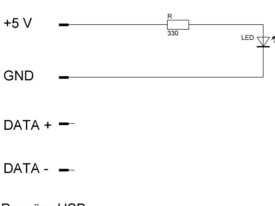
Description of the probe.
When connecting the probe to the device under test, let's call it the donor device, since we will check the supply of +5 Volts from it, plus 5 Volts and ground (GND) are supplied through the USB connector.
A current flows through the limiting resistor and the LED, causing the LED to glow.
The data contacts of the connector (DATA + and DATA-) are not involved, are not connected, therefore they cannot disrupt the operation of the donor device, cause a malfunction in its operation. This is very important when checking the USB port of a desktop computer or laptop.
The current consumed by the LED is many times less than the current allowed for a standard USB output. Therefore, it cannot disrupt the operation of the donor device.
At the same time, it creates some load by simulating a real connected device, this is necessary in some cases.
The brightness of the LED can be used to judge the voltage value +5 V. Of course, the presence / absence of this voltage.
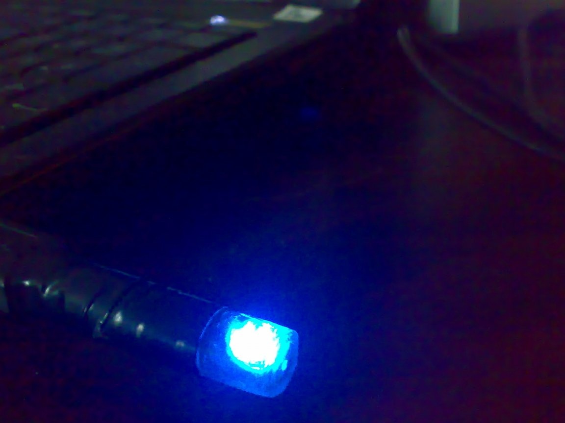
You can observe how the donor device supplies or removes power from its output.
And finally, you can use the probe as a flashlight.
Now I will talk about the assembly of the probe.
Details and materials:
USB port
330 ohm resistor 0.25 W
Light-emitting diode
Pencil case
Solder
Rosin
Lacquer
Insulating tape
Instruments:
Soldering Iron 25-40 W
Nippers
Stationery knife
Permanent marker, in other words CD / DVD / BD-PEN
Small pliers
Tweezers
Hacksaw
Small file
Multimeter (optional)
The probe assembly process.
Step 1.
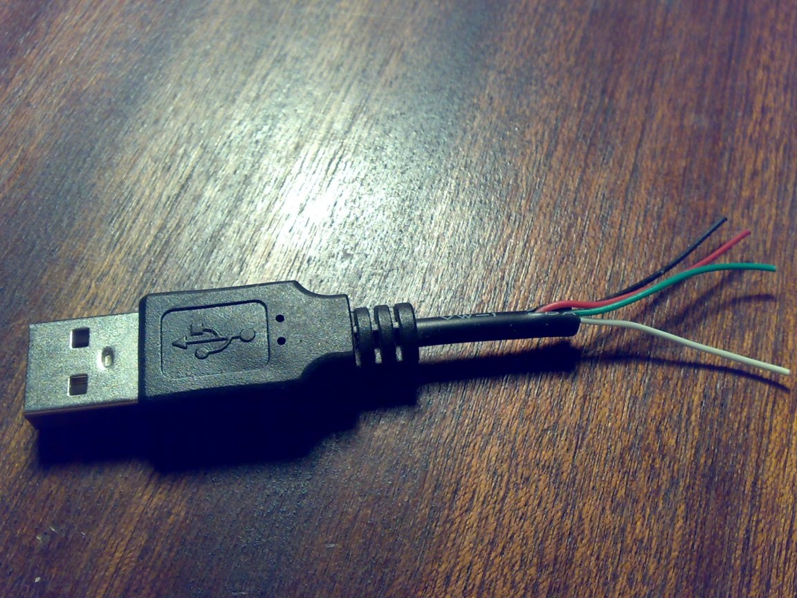
I found in my stocks a cable from a non-recoverable and discarded computer mouse. I cut off a USB connector with a small length of cable from it.
Step 2
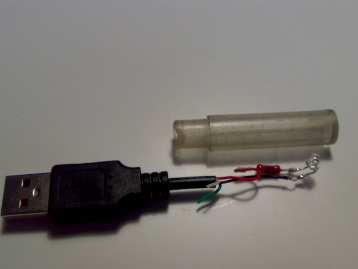
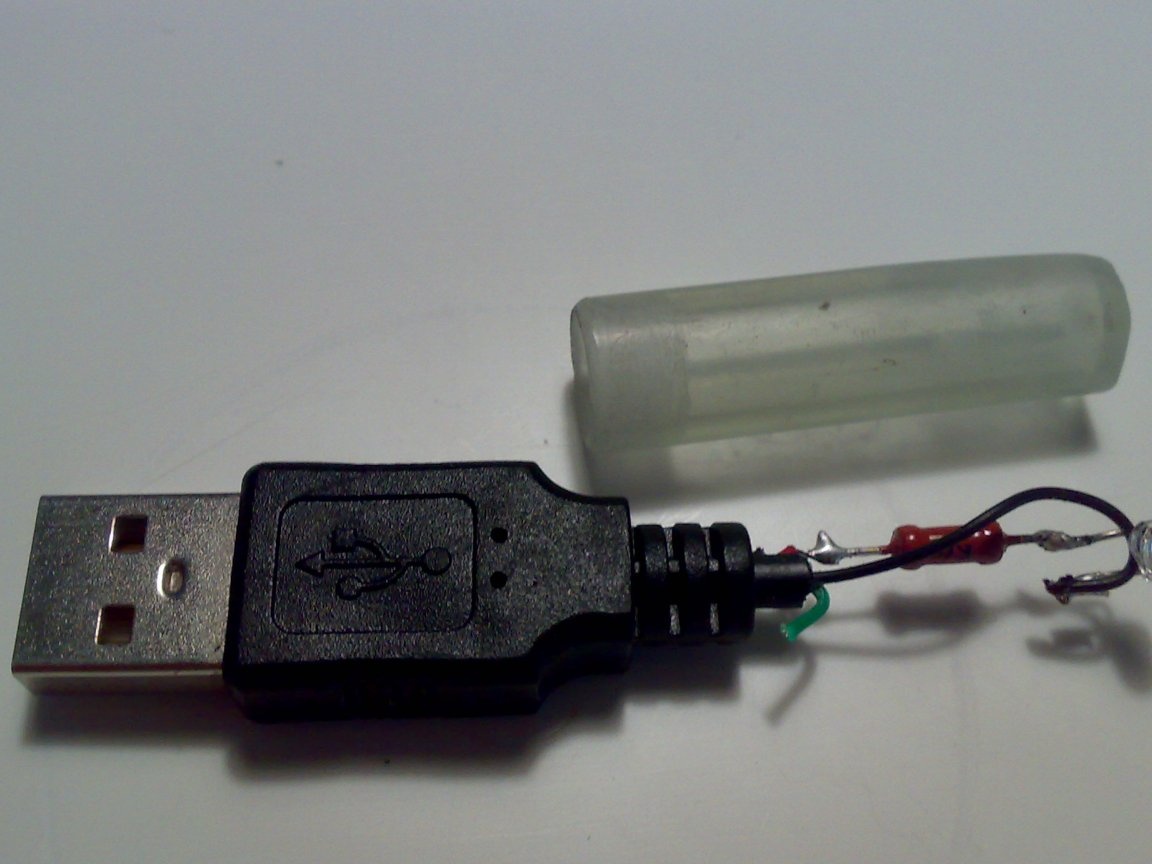
Prepared the details. This is the aforementioned connector, MLT-0.25 330 Ohm resistor and a bright blue LED. I drove out the LED from the removable front panel of the car radio that cannot be restored.

Step 3
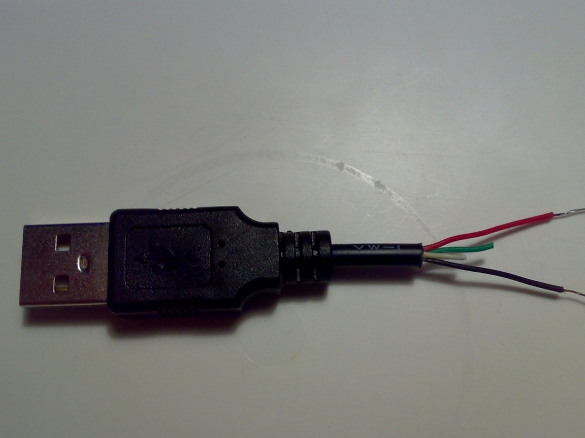
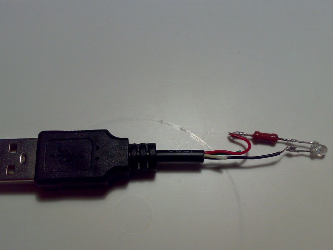
Prepared connector wires for the assembly of the entire circuit. He removed the external insulation, stripped and tinned the red (+5 V) and black (earth) wires. And green and white (data) shortened, they will not connect to anything.
Step 4
Since I pulled out the LED from the board, I did not know where it had the anode (+), and where the cathode (-). Therefore, I determined this with a multimeter. For this, I turned on the multimeter for the semiconductor continuity. I connected the probes of the device to the LED, changing their places. I noticed in which position the LED was lit. I marked the terminal of the LED to which the plus wire of the multimeter was connected with a permanent felt-tip pen. This is the anode of the LED.
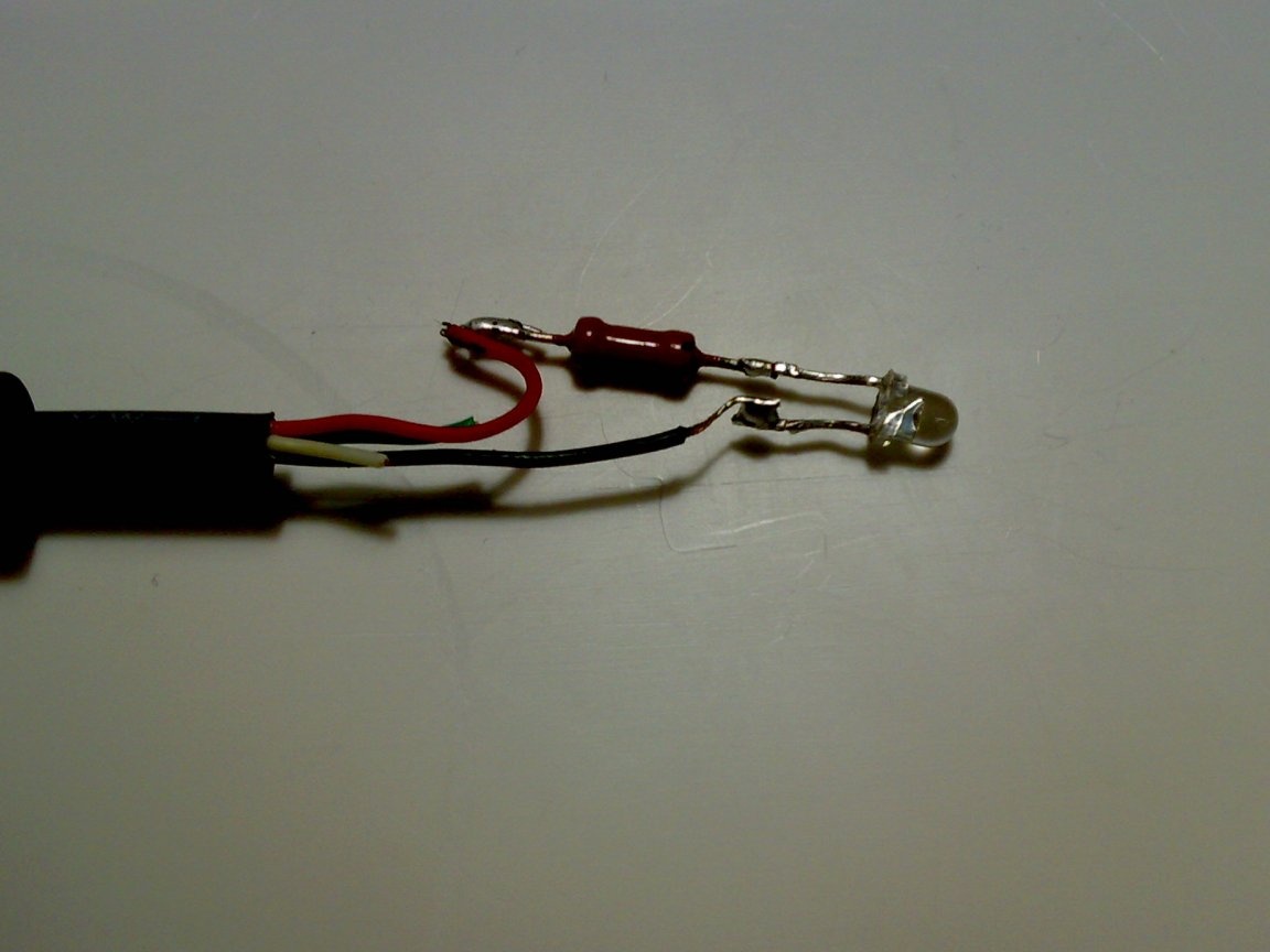
Step 5
I soldered the circuit.
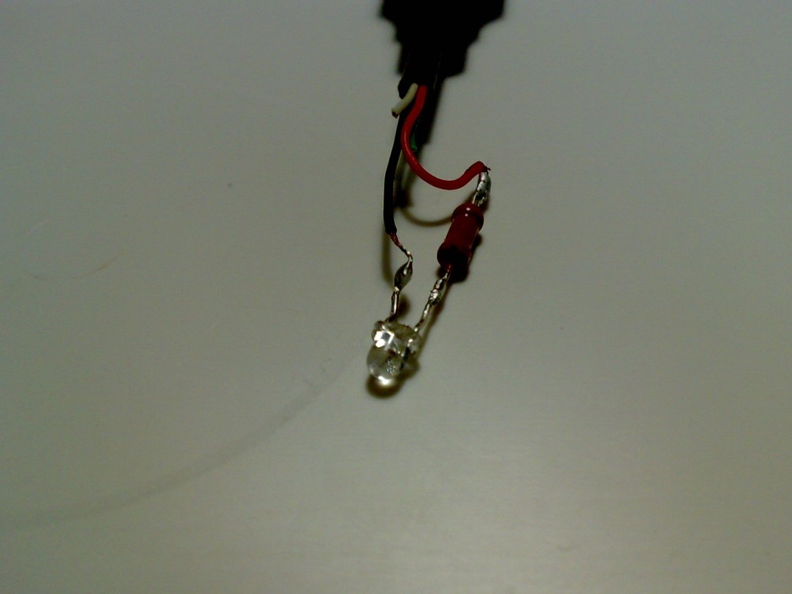
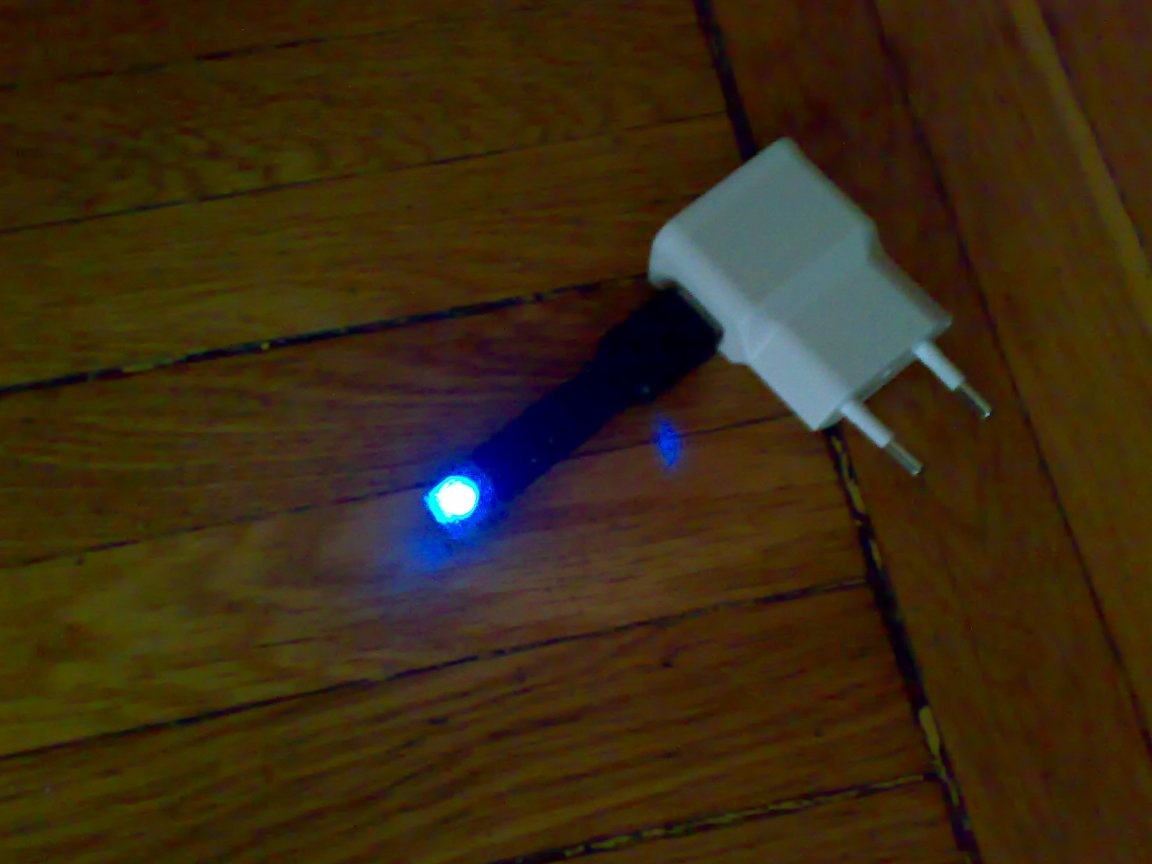
Step 6
I started a preliminary check of the circuit's operability. To do this, connect the probe to a USB charger.
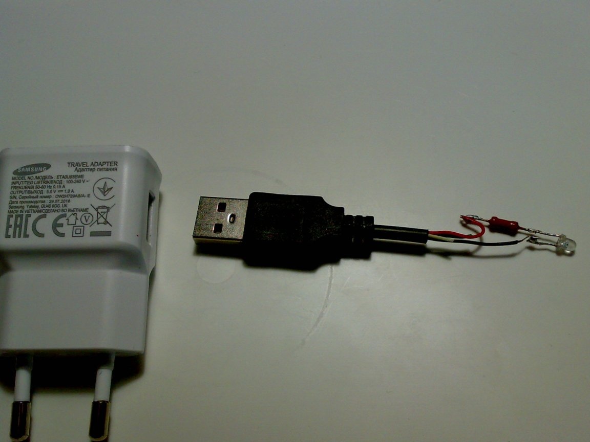
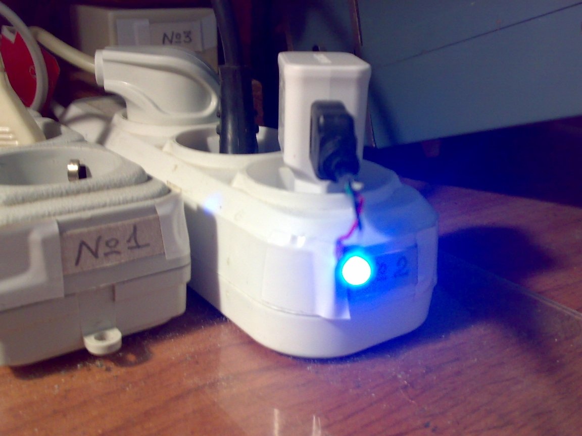
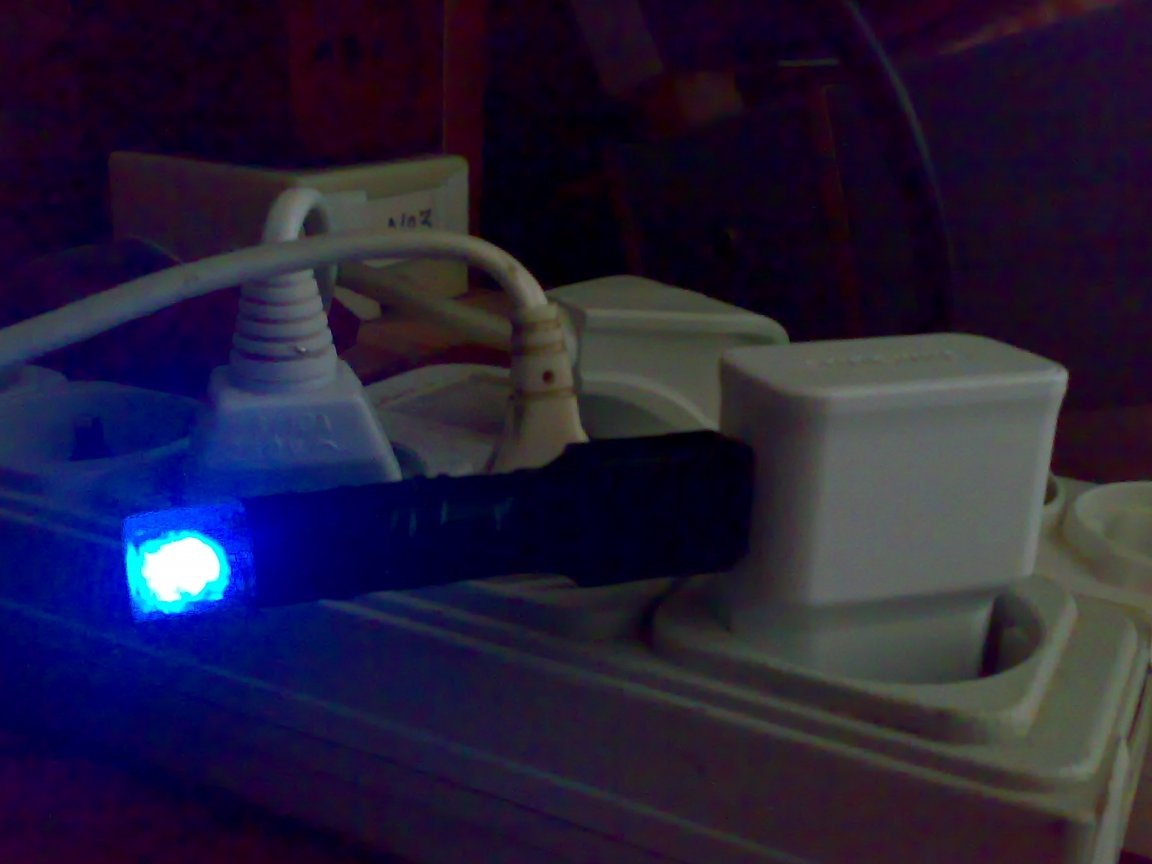
Step 7
I inserted the charger into one of the socket blocks on my desktop. The LED lights up brightly. Excellent! Everything works as intended.
Step 8
Disconnected the charger from the network. But the LED continued to glow for a while.
And with another charger, the LED went out immediately after disconnecting from the network. This suggests that manufacturers have saved on capacitors. I did not find it necessary to take pictures.
Thus, this probe can reveal this nuance.
Step 9
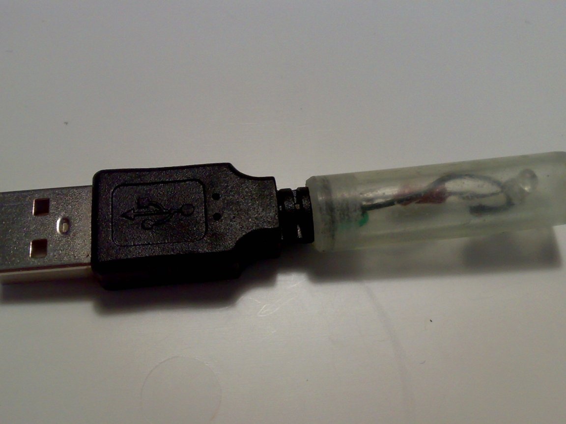
It's time to tackle the probe case. Having estimated the necessary dimensions, I decided to use a small transparent pencil case, in which I used to store small drills.
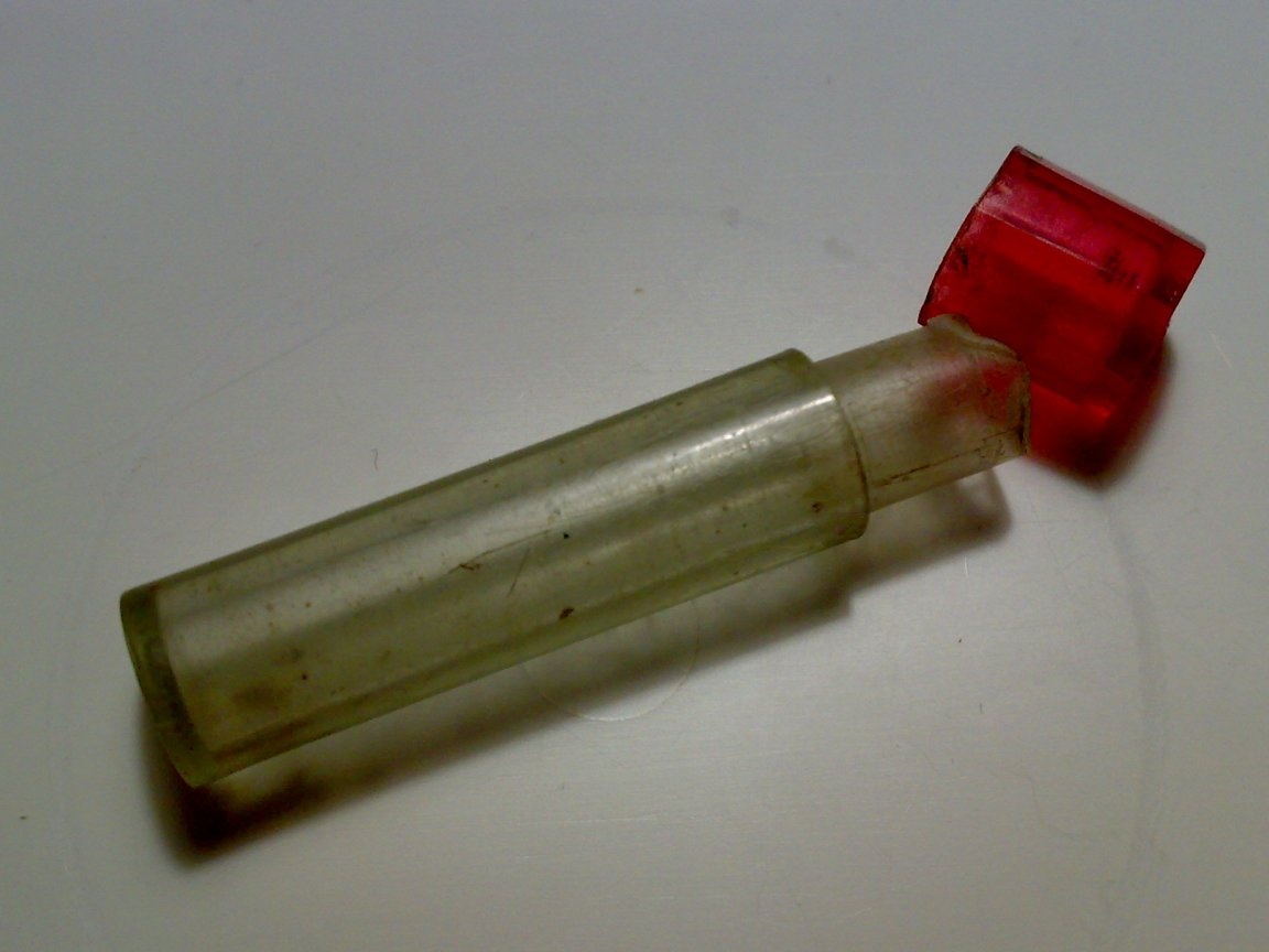
I bent the conclusions of the LED at 90 degrees and positioned the LED so that it shines in the same direction where the USB symbol on the "trident" connector "looks", that is, on the one who plugs the probe into the socket.
Step 10
I noted with a permanent felt-tip pen where it is necessary to cut off excess from a pencil case. I sawed off the excess with a hacksaw and processed the edges with a file. Also, with a file, I expanded the inner diameter of the pencil case in the front so that it fits tightly on the back of the connector.
It turned out that the whole circuit does not fit inside a shortened pencil case; wires interfere. I had to partially solder the circuit, shortening the wires.
I checked how well, tightly, the pencil case is put on the back of the connector. Everything is fine.
Step 11
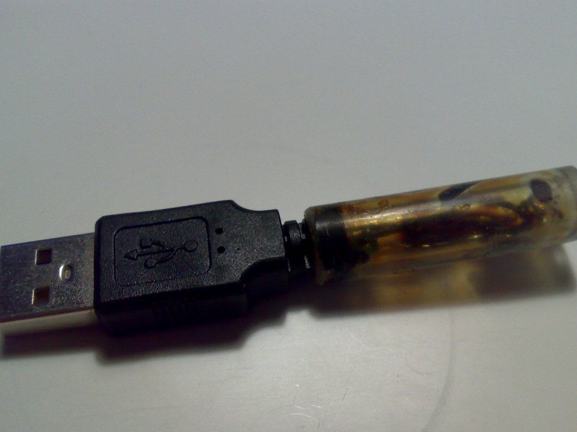
Final assembly. To fix the circuit inside the case I took a varnish. In a good way, it was necessary to take a transparent varnish, but it was not at hand. Used what it was. This did not particularly affect the results of the work. Varnished the details of the circuit and the pencil case from the inside and put the pencil case on the back of the connector.
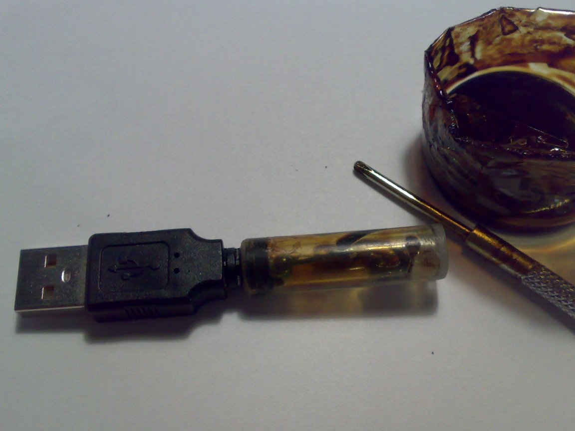
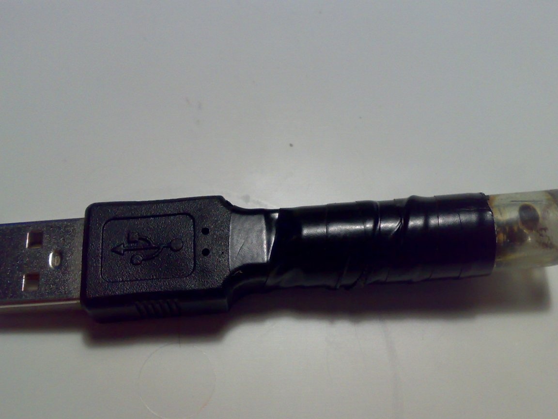
Step 12
Decided for design purposes, I decided to hide the device diagram and wrapped part of the case with black electrical tape. I must admit, it didn’t turn out very beautifully. But he did not remodel, for fear of spoiling the finished product.
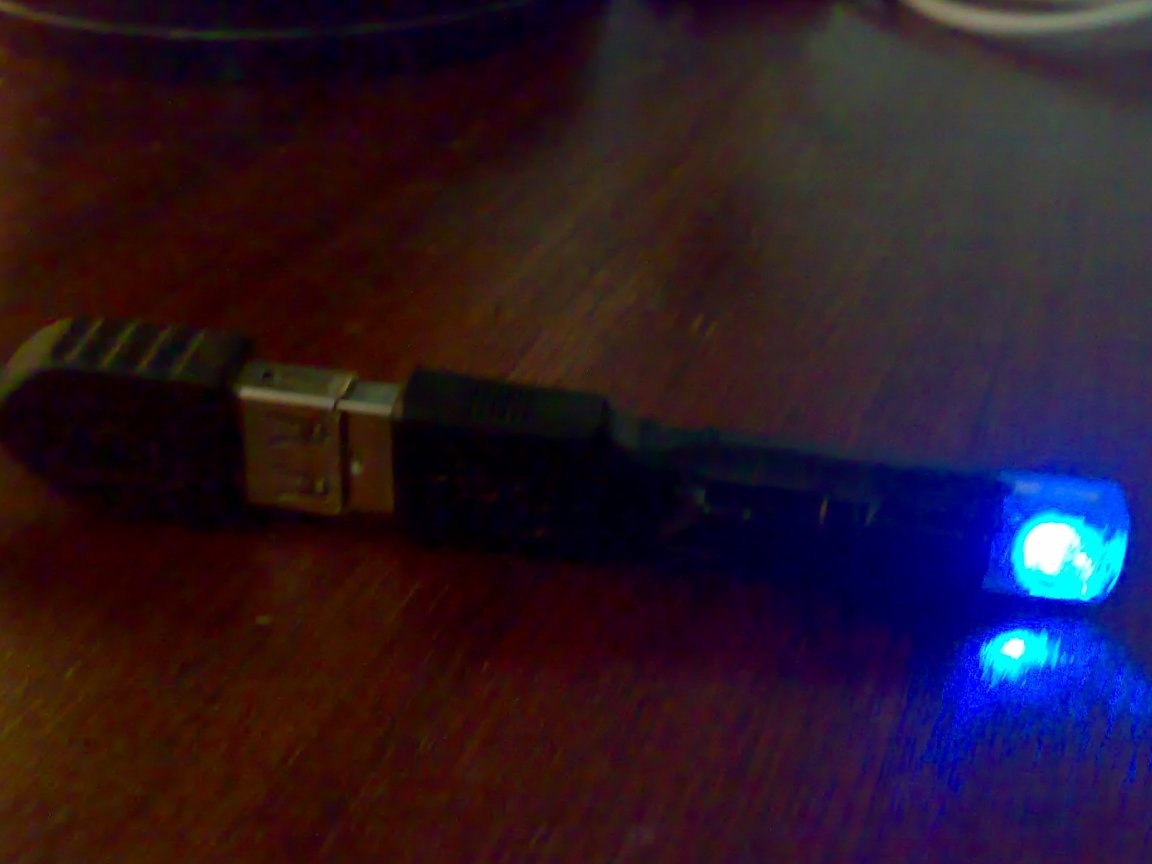
Step 13
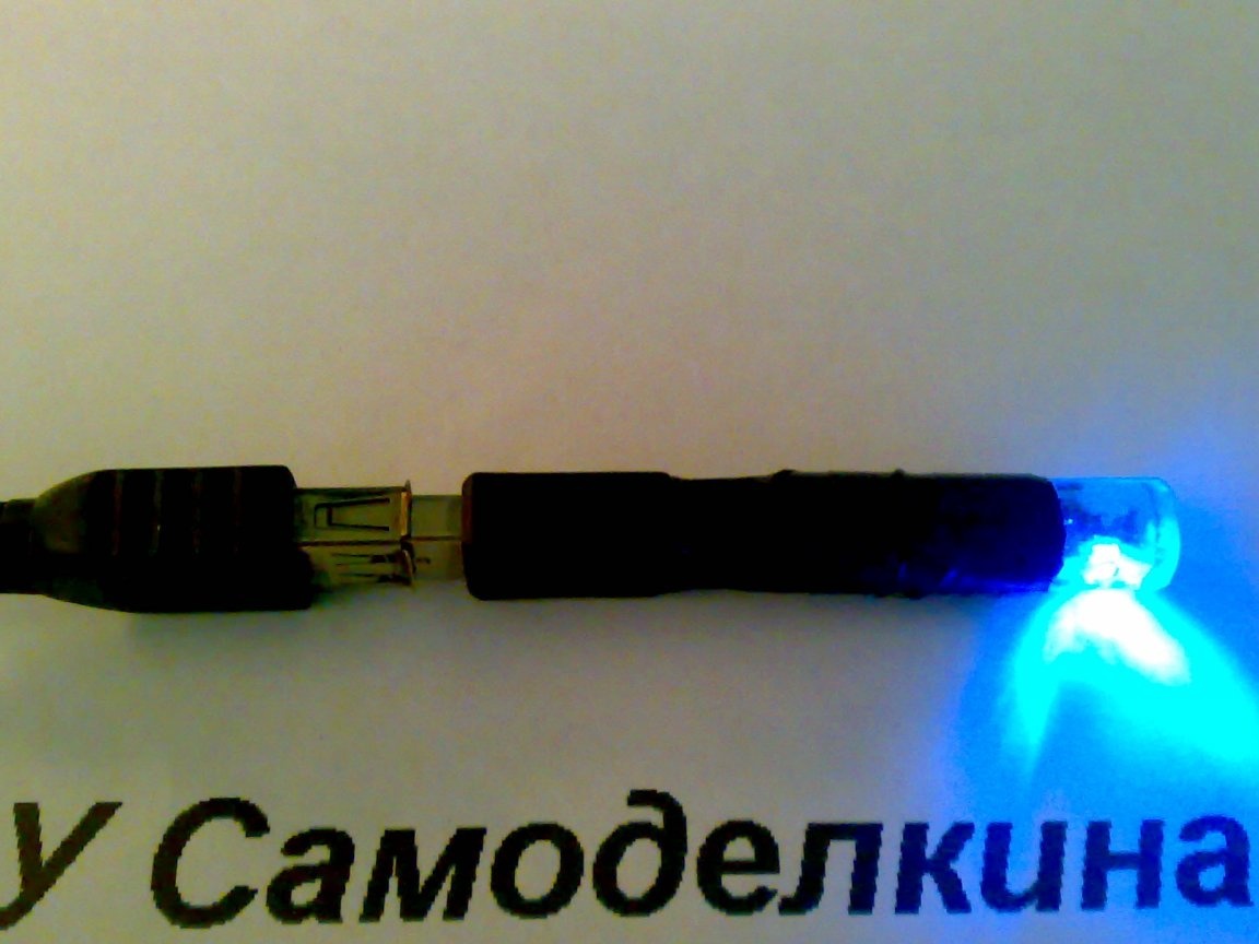
Final test probe. As in the case of the preliminary check, I connected the probe to the charger and inserted the charger into a power outlet. The LED is lit. Everything works! You can use the probe!
Checking the USB of the laptop.
Checking the USB extension cord.
I made this probe about a month ago and over the past period I have used it more than a dozen times. The probe helped me save time on repairing and checking various USB devices.
Hope this homemade and the article will be useful to you.
I will be glad to your comments and suggestions.
Regards, R555.