
In this article, the author of the YouTube channel Radio-Lab will show how you can connect two separate mono audio amplifiers to get one stereo amplifier.
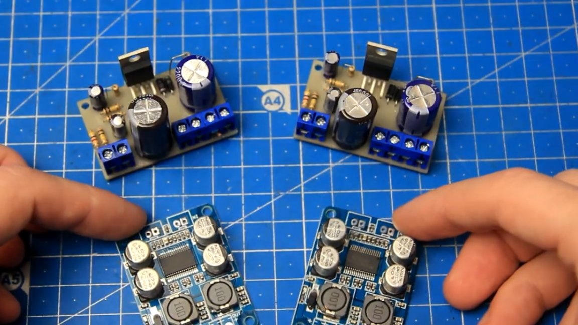
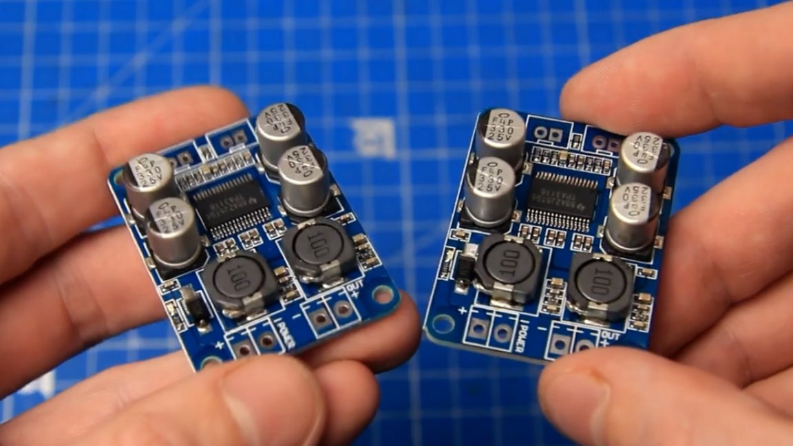
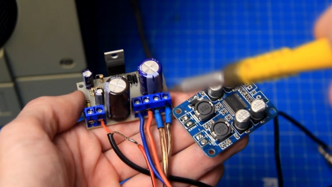
For an example, the author will use two boards of mono D-class amplifiers on microcircuits TPA3118, as well as a couple of boards of mono AV class amplifiers on microcircuits TDA2030a.
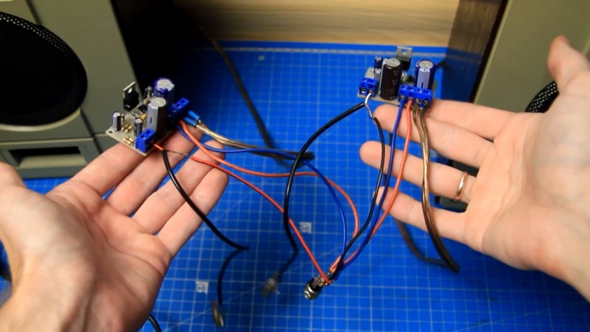
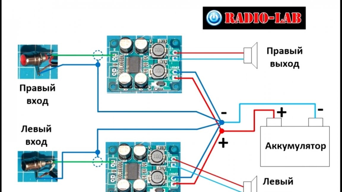
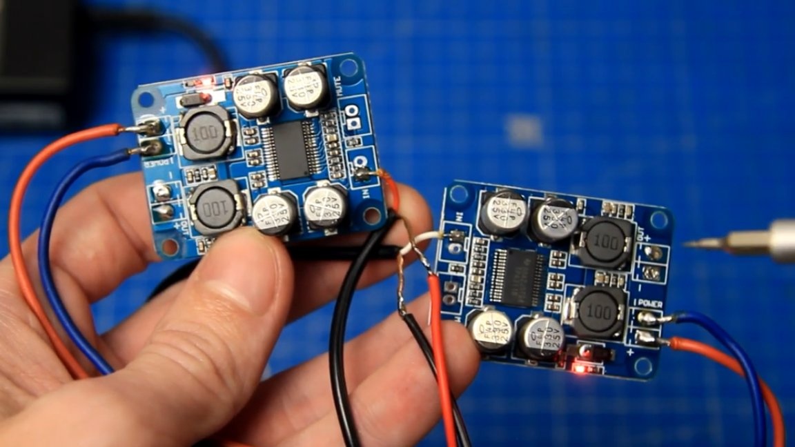
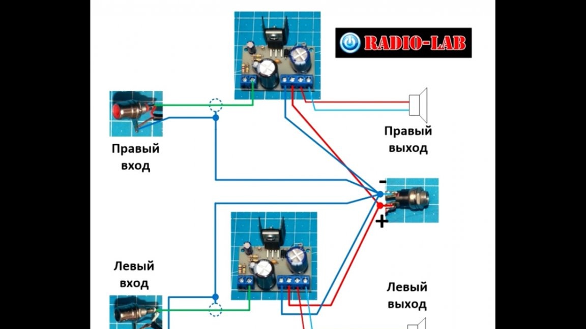
The unipolar power amplifiers presented above are when 2 wires are needed for power: one is plus and the second is minus. If stereo amplifier on one board, then everything is clear with this: input, output and power.
But when we are dealing with two mono amplifiers on separate boards, then certain questions already arise, especially for beginner radio amateurs.
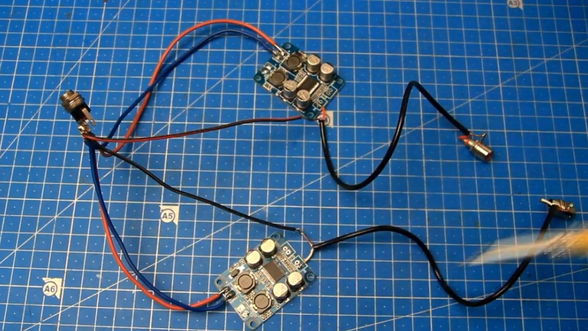
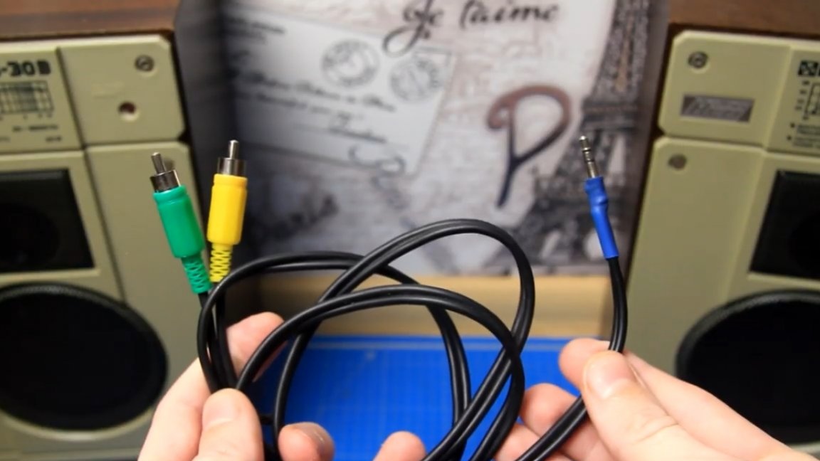
To send a sound signal to the sound amplifier board, you will need RCA connectors (tulips).
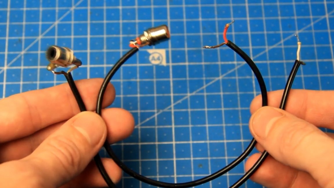
They must be soldered to the connector pins.
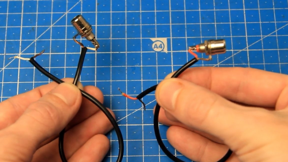
Each amplifier needs its own wire with a connector.
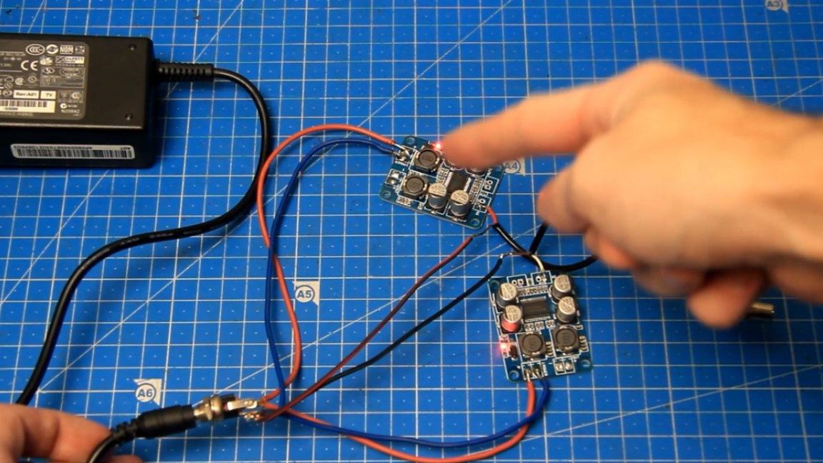
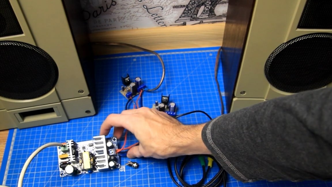
To power the amplifiers, the author decided to use such a pulse laptop power supply with a voltage at the output of 19V and a current of 4.74A.
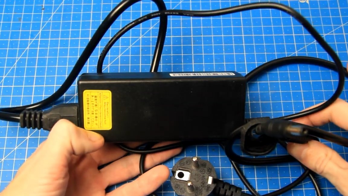
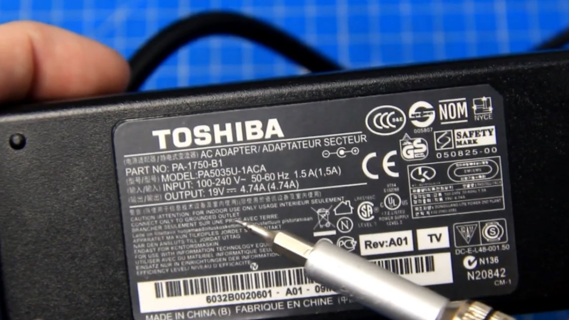
This value of the supply voltage (19V) falls into the allowable range of supply voltages of the aforementioned amplifiers.
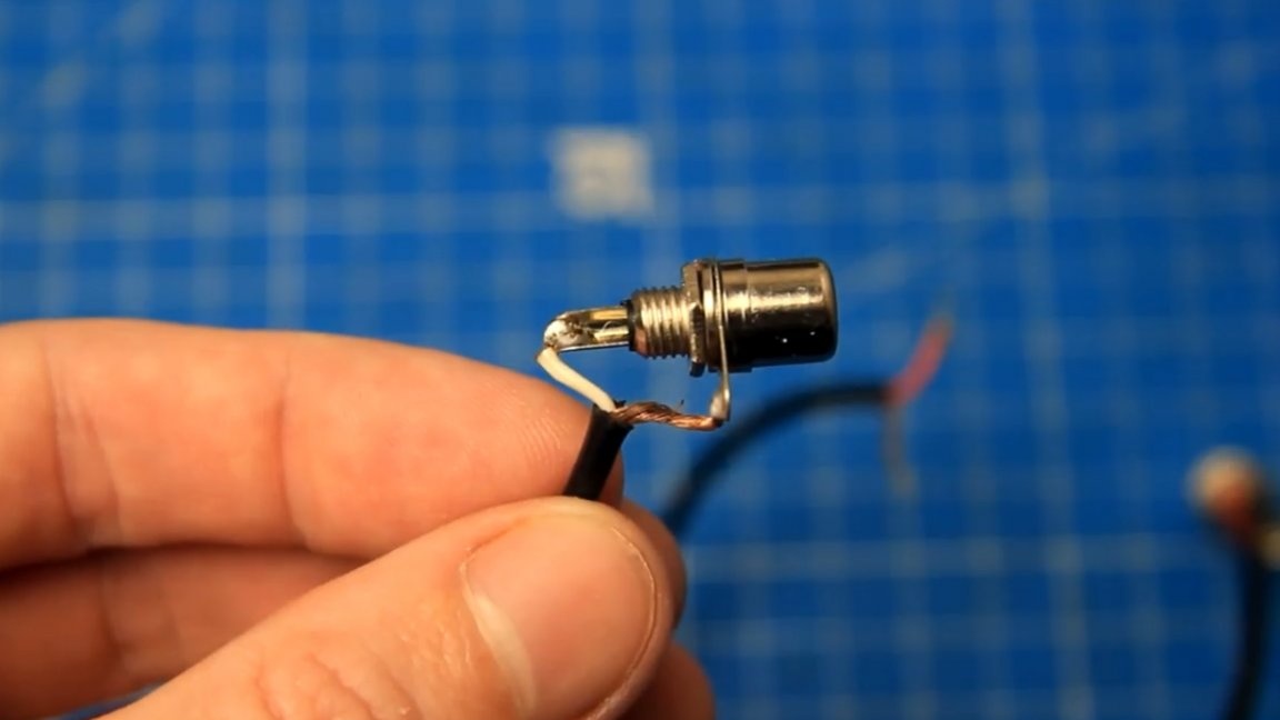
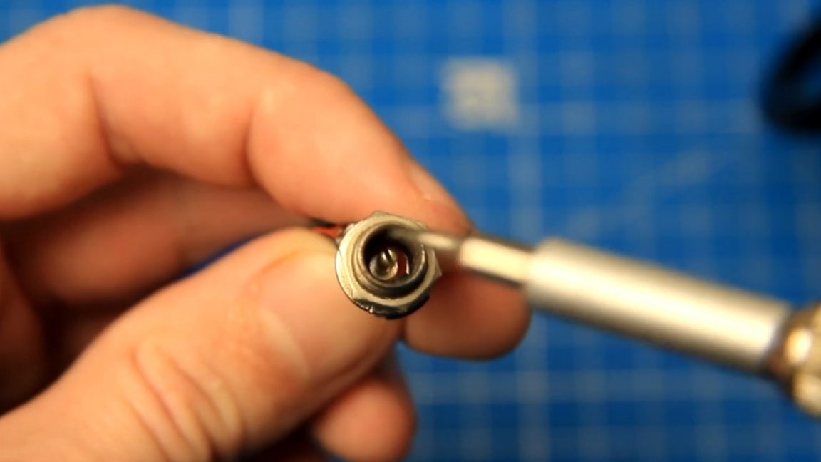
To connect the boards to the power supply, such a 5.5 x 2.5mm connector will not be out of place.
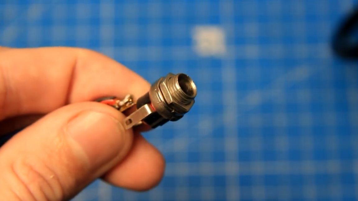
The pin in the middle in this example is plus (+), and the pin in a circle is minus (-).
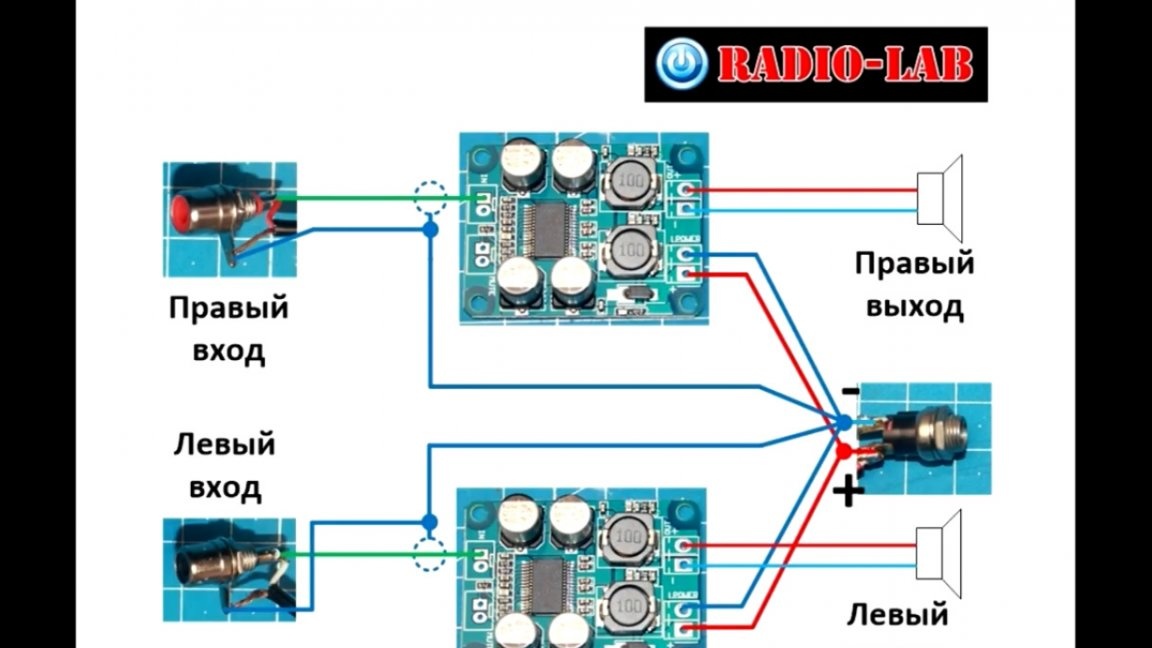
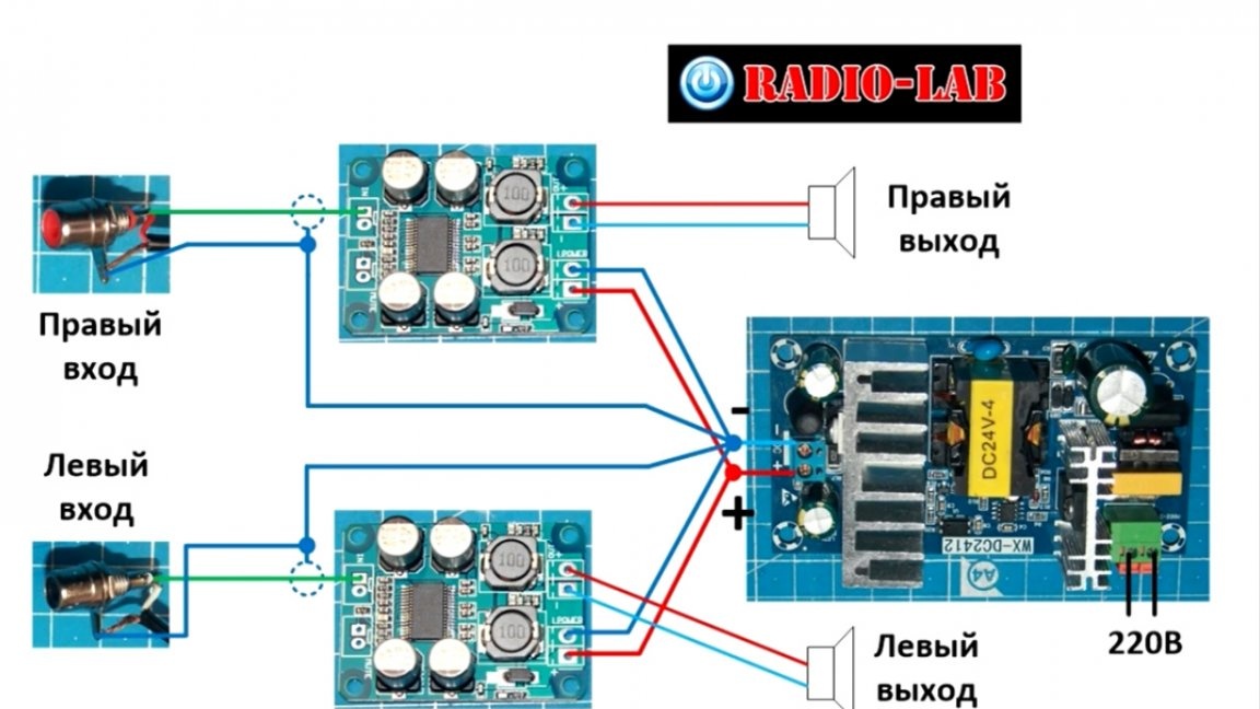
For easier understanding, the image below is wiring diagram amplifiers:
When using battery power, the connection is done in the same way.
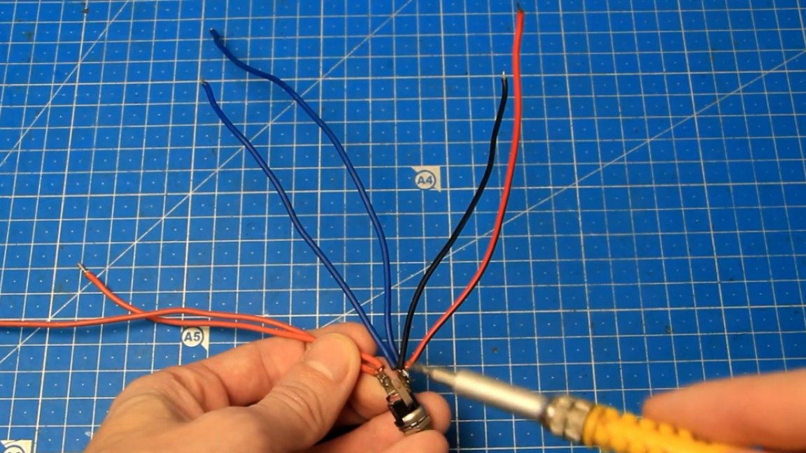
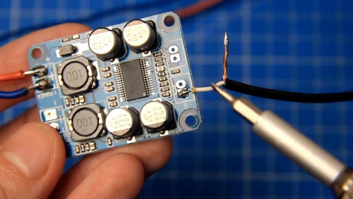
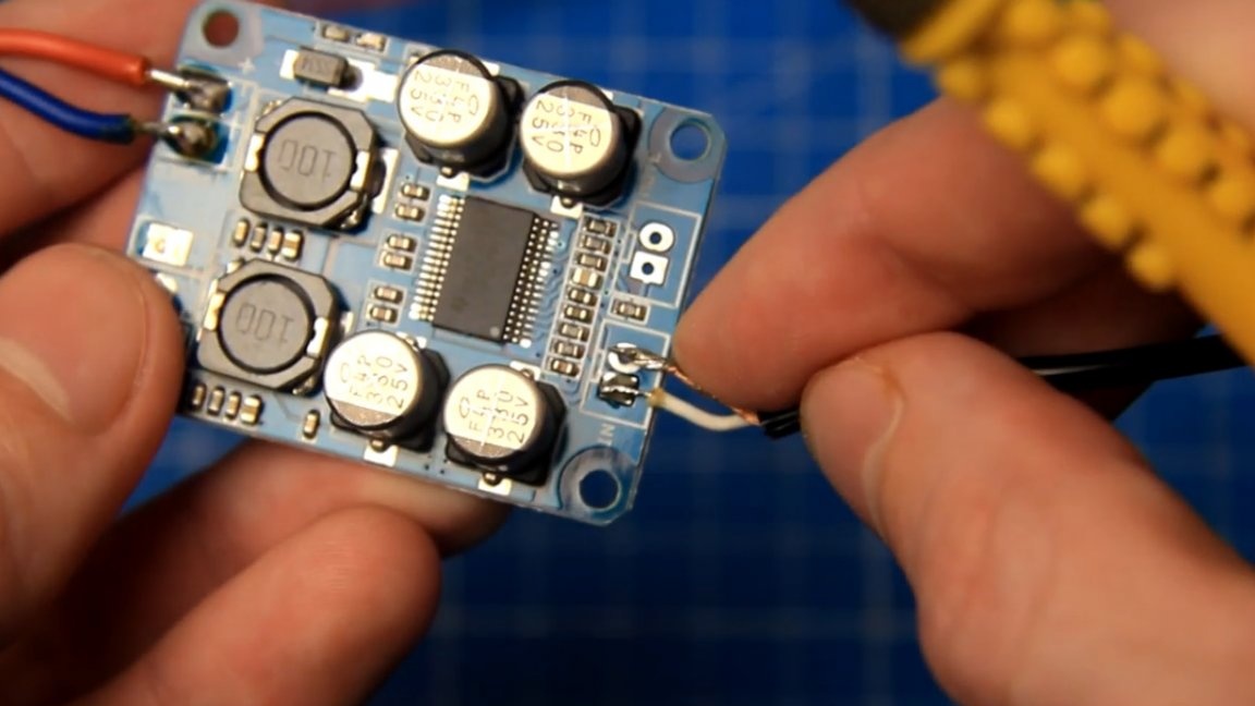
Further, observing the polarity, solder to the contacts of the power connector all the necessary wires.
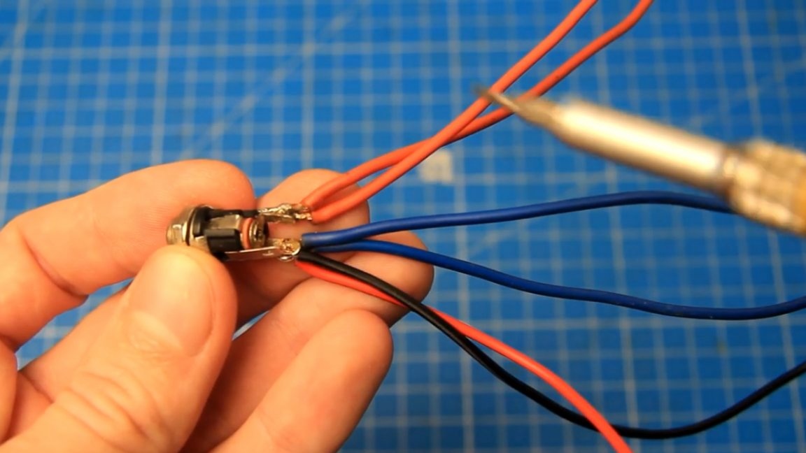
The author soldered 2 red wires to the positive contact, and 2 blue wires to the negative contact. Also, a couple more thinner wires were soldered to the negative contact for connecting to the shields of the input wires to the amplifiers.
As a result, all the cons seem to converge at one point closer to the power source. Such a connection according to the "star" scheme makes it possible to get rid of the loops in the negative and thereby eliminate the likelihood of the formation of various buzzes, interference, interference and other troubles.
In the case of the power supply, all connections must be made as close as possible to the terminals of the power supply.
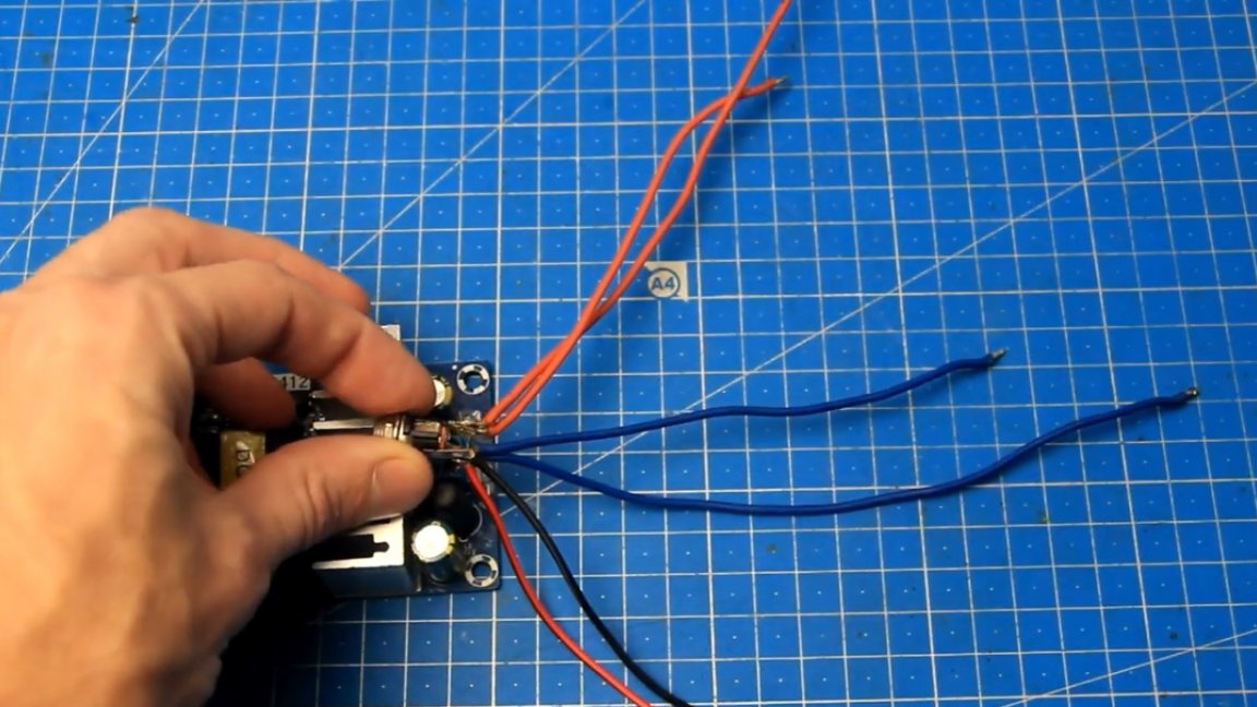
When soldering the power wire to the power contacts on the sound amplifier boards, be sure to observe the polarity! Next in line we have input wires with connectors.
On the amplifier board there are corresponding input contacts, one signal, and the second negative. The signal contact in this amplifier is indicated as plus (+).
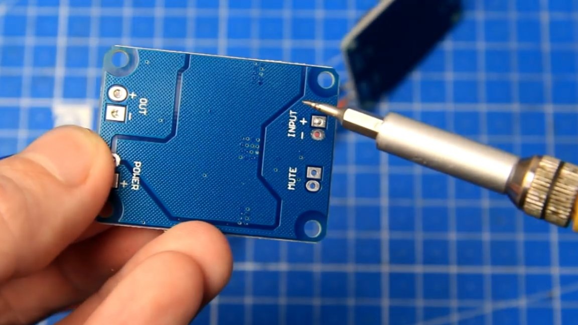
The signal wire, which is isolated, is soldered to the signal input of the amplifier with a plus (+) mark, and the screen wire can be soldered next to the negative terminal.
But it is worth considering that with such a connection, loops in the minus may appear in the circuit and noise may occur in the columns. If everything is done wisely, then in this case it is necessary to reduce all the minuses to one point according to the "star" scheme.
Pull the power wires first to one amplifier, and then from one to another is not desirable.
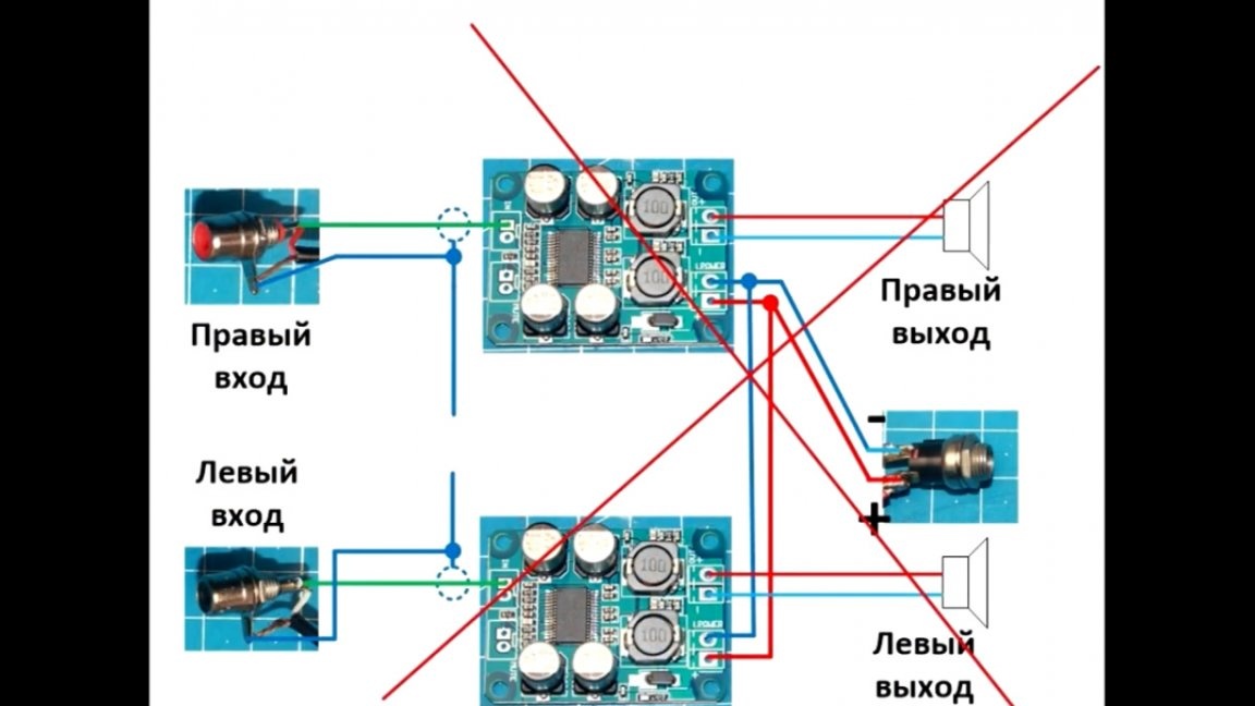
Correctly and in theory - this is to pull the power wires to each amplifier, and all the minuses (they are also the earth in amplifiers with unipolar power), and sound as well, you need to pull it to one common point according to the "star" scheme and thereby forcibly setting the paths of movement current, so that the current does not arbitrarily reel according to the scheme.
In short, the appearance of background noise in the speakers is associated with different lengths of audio ground wires and minuses of the power wires, and the current, as we know, flows along the path of least resistance. Thus, if the circuit assembly is not correctly assembled, it can turn out that the current of the supply minus partially or completely flows, for example, by the same sound minuses. This will lead to a drop in the supply voltage at the sound minus, there will be a formation of a weak magnetic field, there will be a tip from this weak magnetic field to the input wires or tracks on the boards, and in the columns we will hear a background buzz.
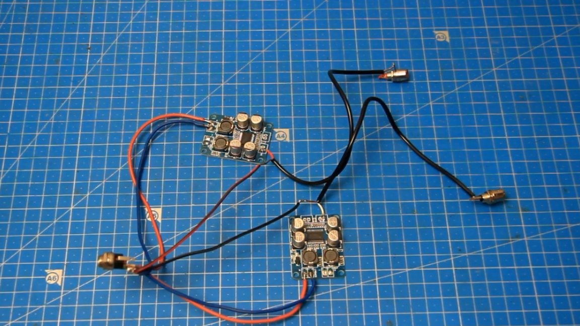
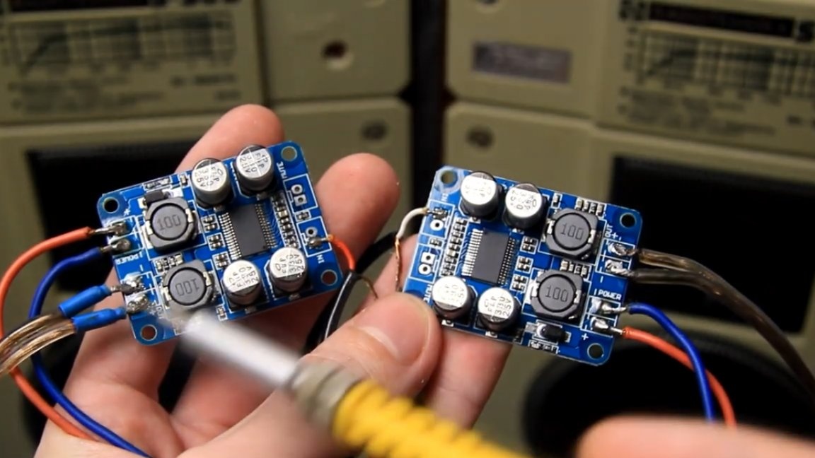
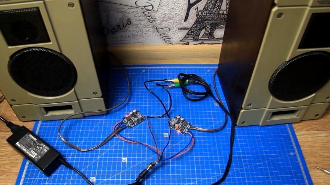
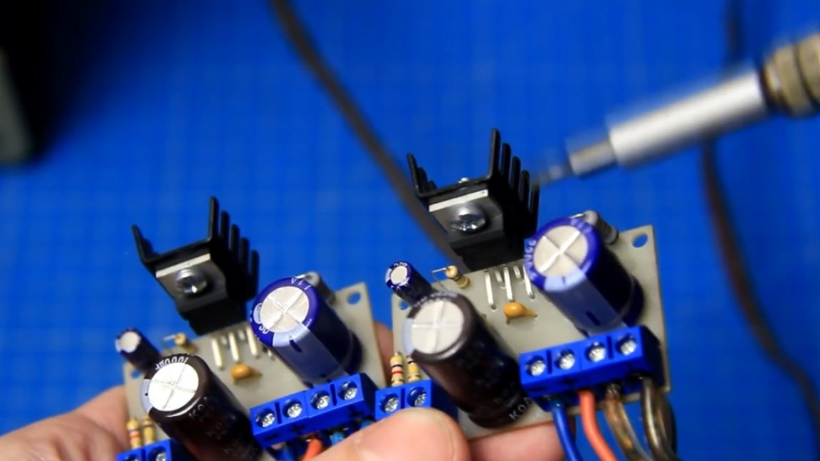
Here is the assembled circuit, consisting of two amplifiers:
If you do everything slowly, then no difficulties should arise. The next step is to try to supply power to the amplifiers, but before that you need to check everything again and make sure that the assembled circuit is correct, and only after that you can confidently connect the power supply to the power connector of the amplifiers.
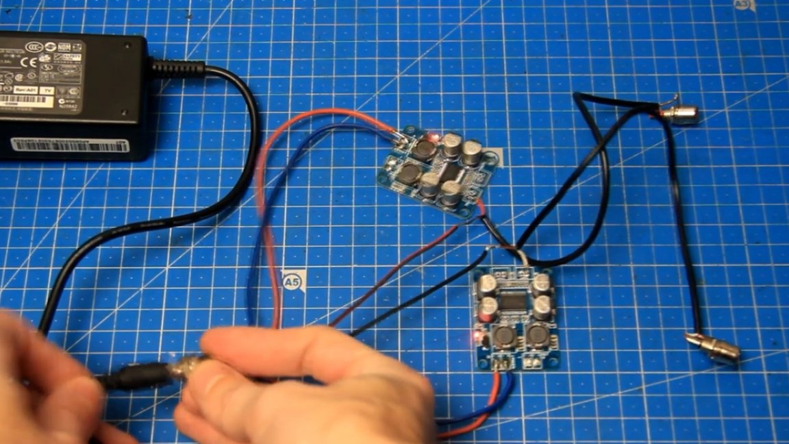
As you can see, the LEDs on the amplifiers lit up, which in turn signals the presence of power. Great, the amplifiers are powered.
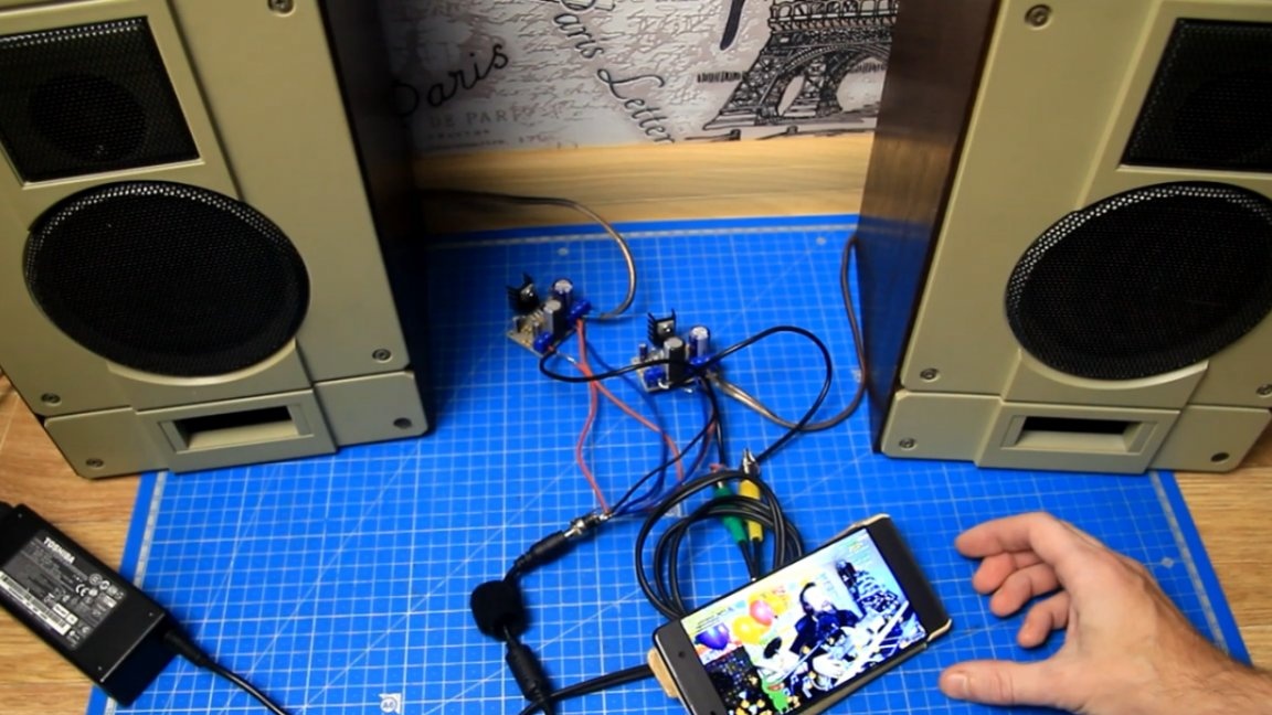
For the test, the author decided to use the Radio Engineering S-30B speakers.
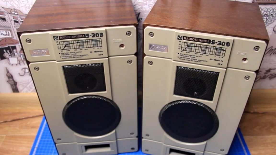
Be sure to observe the polarity, it is necessary to solder the wires from the speakers to the contacts of the outputs of the sound amplifiers.
To provide a sound signal to amplifiers such a cable with connectors: on the one hand - a 3.5 mm minijack, on the other - 2 RCA, they are also tulips.
Everything is ready, you can begin to test the performance. The first thing we do is power the amplifiers.
There was no popping when turned on, but there was not a lot of background noise in the speakers. This background is due to the fact that the inputs of the amplifiers are not connected anywhere and the circuits at the inputs are open, in this case the background is normal. To get rid of the hum, you just need to connect the sound source to the inputs of the amplifiers and close the circuit at the inputs.
The sound source will be a smartphone. We again supply power to the amplifiers and plug the 3.5mm plug into the phone.
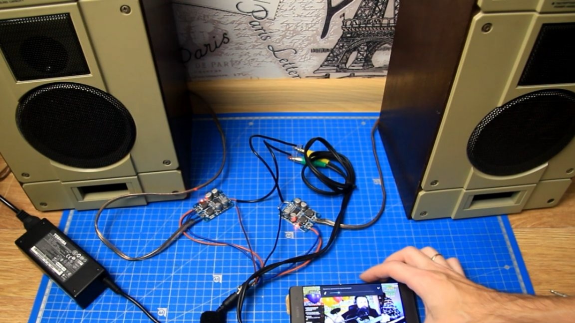
The input circuits are closed and the background is completely gone. Music sounds from the speakers, therefore, the amplifiers work. At minimum volume, complete silence, no extraneous noise, no interference either, the circuit works fine, so everything is assembled correctly.
Similar AV class amplifiers with unipolar power supply are connected in exactly the same way as class D amplifiers with unipolar power supply, similarly, class A amplifiers with unipolar power supply, etc. Regardless of the class of the amplifier, it has input, output and power, and they are all connected the same way. Of course there are exceptions, but they are rare.
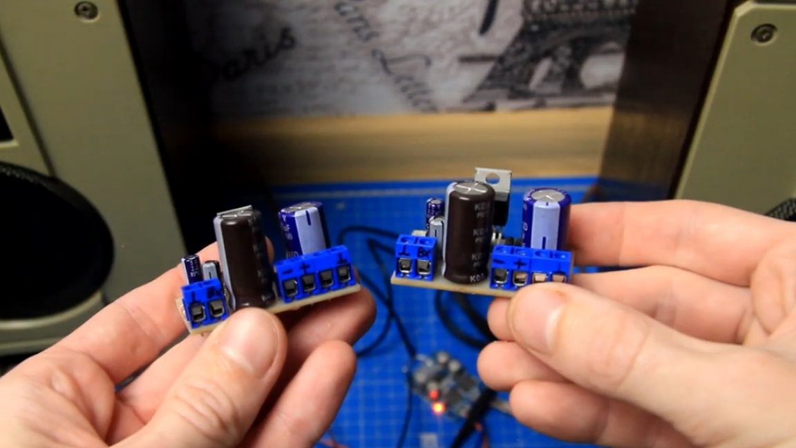
To demonstrate this, the author, instead of amplifiers on TPA3118connected the amplifiers to TDA2030aThe power supply voltage of the amplifiers allows them to be powered from 19V.
For the duration of the test for microcircuits, it is advisable to screw small radiators. After that, we supply power to this assembly.
If the phone is not connected, then the background is also present, although the class of amplifiers is already AB. Accordingly, when the phone is connected, the background disappears and at minimum volume in the columns there is complete silence similarly with D-class amplifiers.
Further, the author decided to try to power the assembly from such a pulse power unit, with an output voltage of 24V.
Everything works and plays, but in the speakers there is a characteristic ringing high-frequency background at a minimum volume. This background comes precisely from the operation of the internal pulse circuit of the power supply, which we eventually hear from the speakers.
If we change the AV class amplifiers to the D class amplifiers, the background practically disappears, but still at a minimum volume it can still be heard. So it’s best to try and select the right power supply specifically for these tasks. For the test, pulsed power supplies were used, but transformers can be used in a classic way, this is already optional.
That's all. Thank you for attention. See you soon!
Author's video: