
Using the so-called radio buttons - virtual switches with dependent latching in the design of various interfaces - modern programmers rarely think about why they are called that way. The thing is, where their real mechanical prototypes were used first - in radiol. Press one key - the one that was pressed before this returns to its original position. Then, such switches - large, as in the same radios, and small, as in the P2K series - began to find application in car radios, portable cassette recorders, three-program receivers, televisions and other equipment. And in floor fans they can still be found.
Transistors, and then microcircuits made it possible to manufacture electronic analogs of switches with dependent latch. They are called multistable triggers. Specialized microcircuits, for example, K04KP020, allow them to be implemented with a minimum number of external elements. It is possible that you once had, or even still have a TV with a switch on this chip.
When graphical interfaces (GUIs) began to spread in computer technology, it became necessary to implement virtual analogs of such switches in them. In their name, the programmers decided to perpetuate their original purpose, and they called it - radio buttons. For example, in HTML they are implemented So.
If you for any homemade, say, the amplifier input selector, you will need a multi-stable trigger, take for it any specialized chip is somewhat unsportsmanlike. The author of Instrictables under the nickname throbscottle implemented such a device on a general-purpose chip - 74HC174 (КР1564ТМ9), containing six ordinary D-flip-flops.
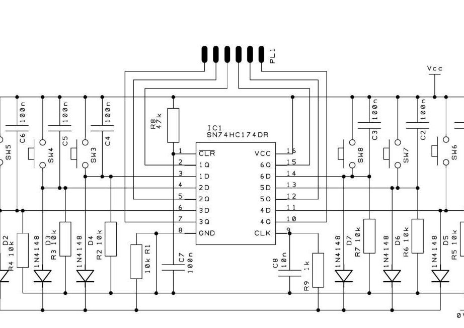
All that is needed to combine these triggers into one multi-stable one is an OR diode and an RC circuit that provides reset when turned on. And so that the device can be controlled by buttons, the wizard adds capacitors to suppress contact bounce and pull-up resistors. He has the following scheme:
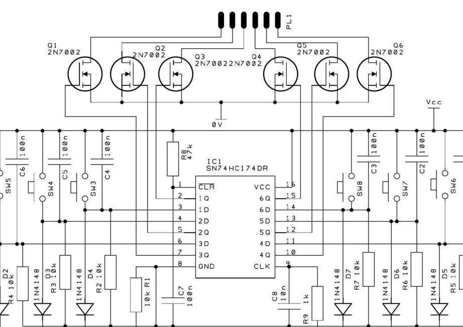
To control the loads from the device, say, the relay windings in the amplifier input selector, you need to add transistor switches, for example, such as shown below. You can perform the keys on bipolar transistors, then we need resistors that limit the base current. Parallel to the windings, diodes in reverse polarity should be connected (not shown, as are the windings themselves).And when connecting to the outputs of the LEDs, they only need one resistor, because in any state of a multistable trigger only one LED is turned on. In the circuit diagram of the microcircuit K04KP020, the same is done.
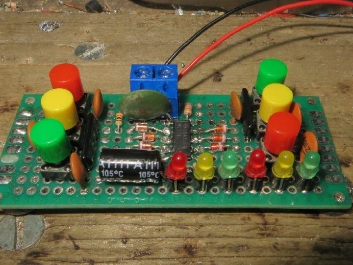
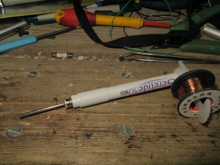
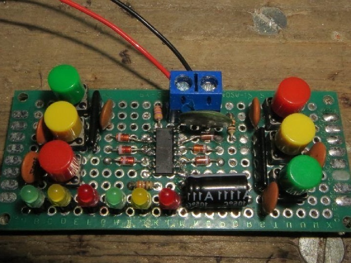
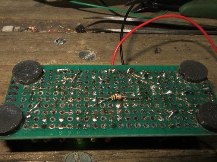
The wizard simulates the operation of the device in the program Logisim. It turns out such a file, the extension of which after downloading and before opening in this program should be changed from unknown to circ. After making sure from the simulation results that the circuit is correctly drawn up, the master assembles it with a winding wire on a breadboard type breadboard. Since he uses the chip in the SOIC package, he bends its conclusions through one. It’s more convenient to solder them. Rubber feet on the back of the board do not allow it to move around the table when the buttons are pressed, and thanks to the pushers, it is more convenient to press them. Perhaps the use of homemade pushers.

And finally, the wizard checks the finished construction in action:
Before implementing the same algorithm on Arduino A multi-stable hardware trigger has the following advantage: it does not have a clock generator that thrashes continuously and can cause interference that is very undesirable when used in equipment of a fairly high class.