
Today we will look at how do it yourself make cool electronic the device that all students dream of - a miniature digital cheat sheet!
The author of this homemade product is AlexGyver (YouTube channel "AlexGyver").
Winter is coming, which means students will have a session soon. And you need to prepare for the session, and prepare wisely. Six months ago, Alex already told how to make a virtually imperceptible cheat sheet with your own hands, with which you can write off any test for which the answers are known in advance. Moreover, to write off as discreetly as possible, without committing absolutely no actions that can be regarded as cheating.
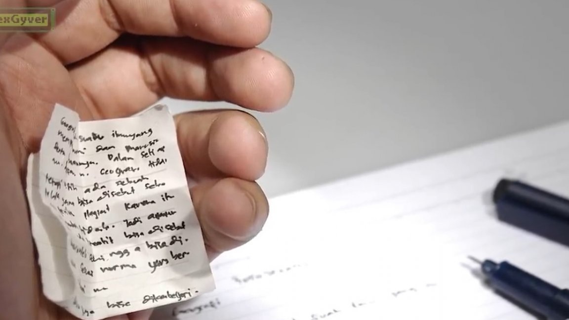
This time we will try to make something more classical, similar to a piece of paper with very finely written text.
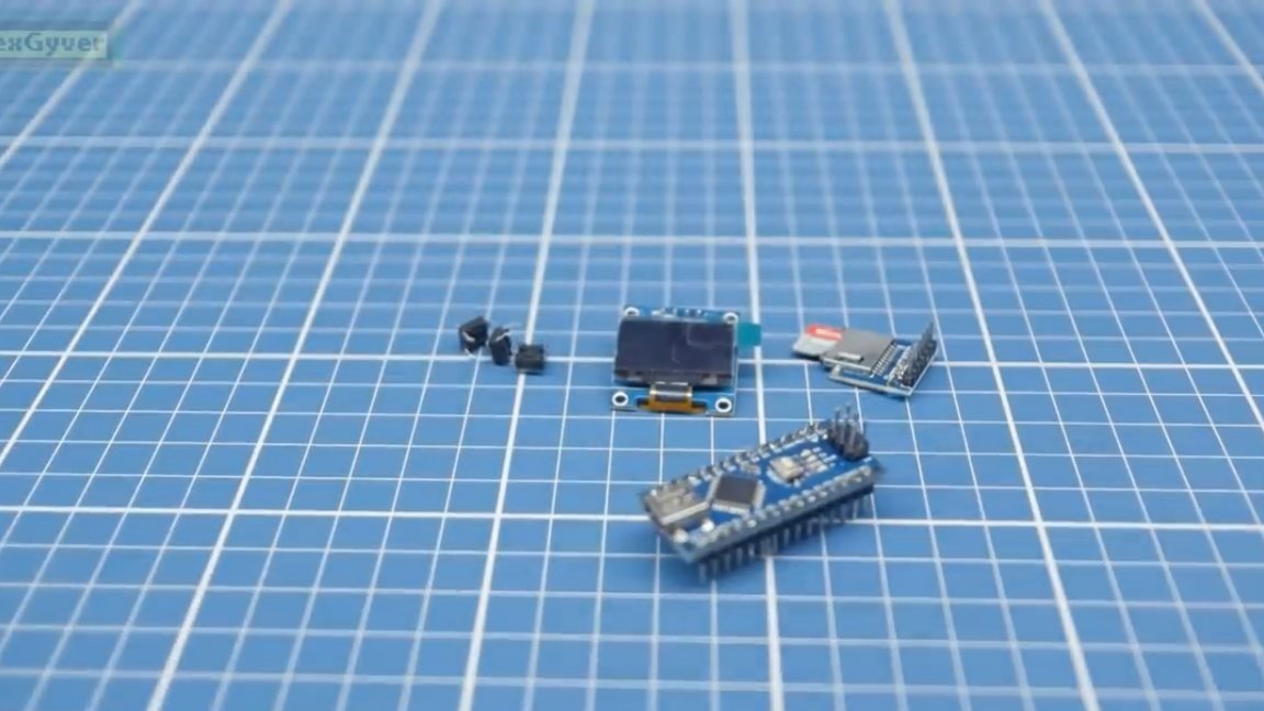
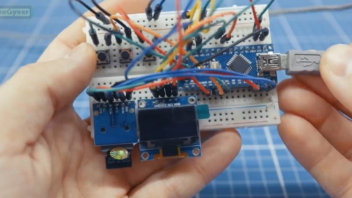
So, to repeat this project we will need:
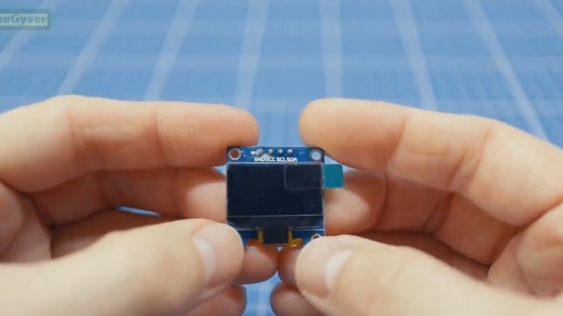
- OLED display with a resolution of 128 by 64 points with i2c connection, 4 pins;
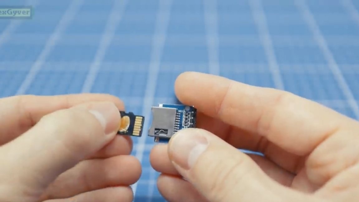
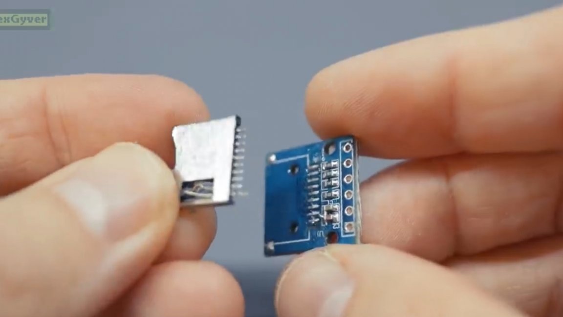
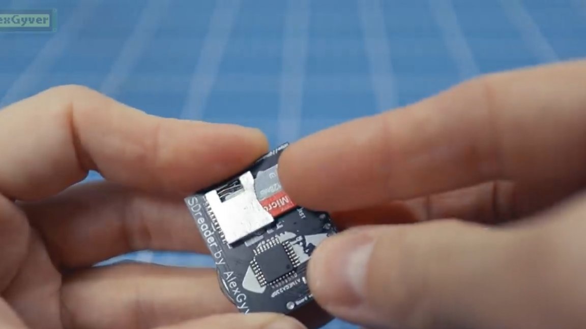
- card slot;
- directly the microSD memory card;
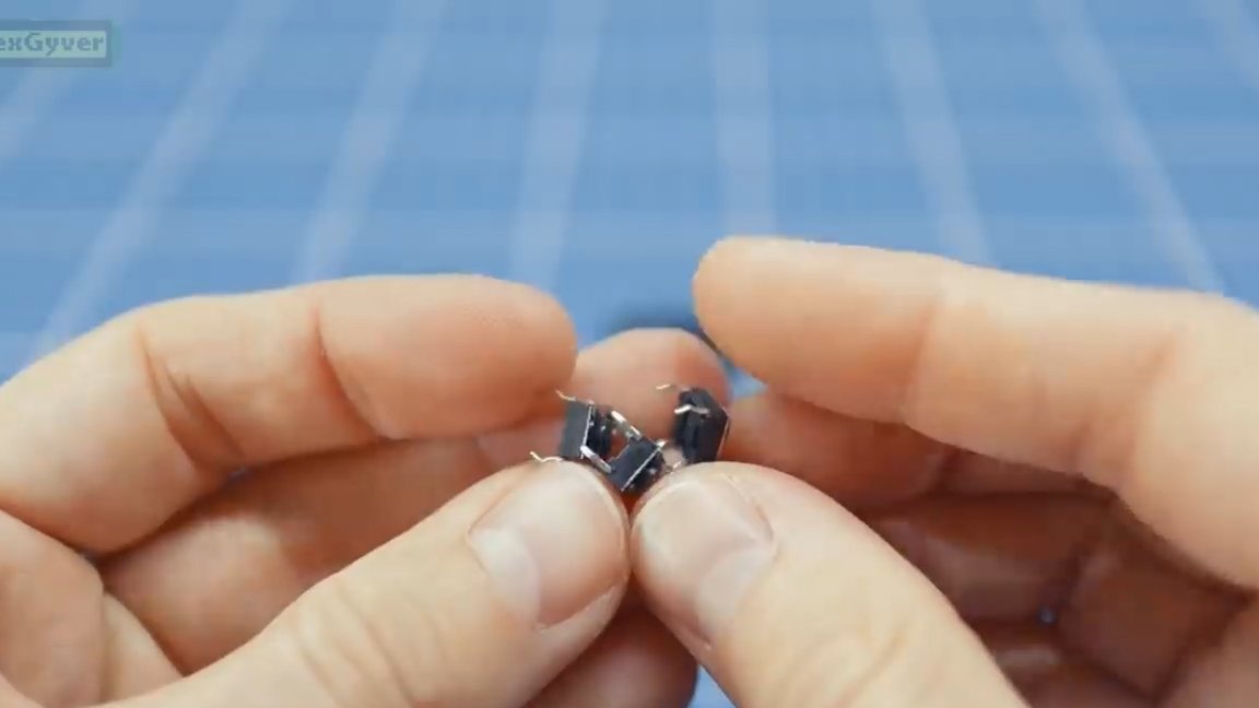
- buttons to control 3pcs;
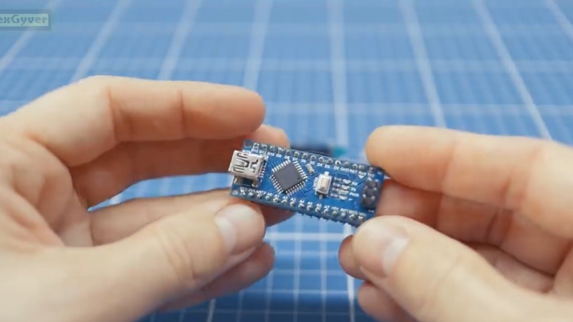
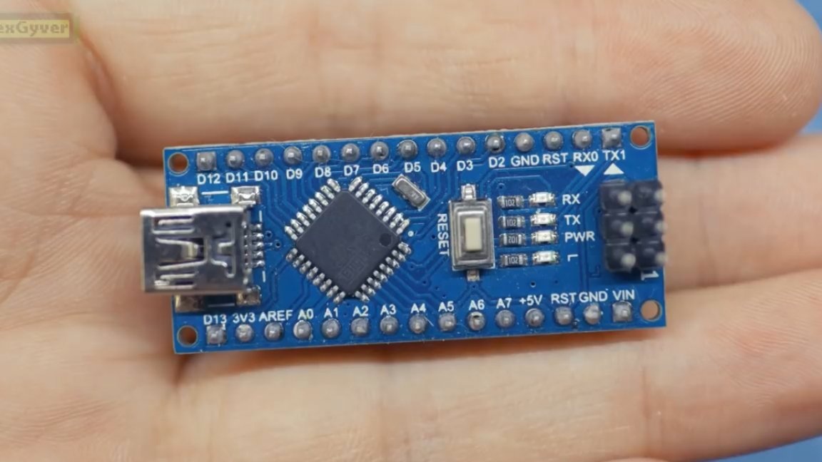
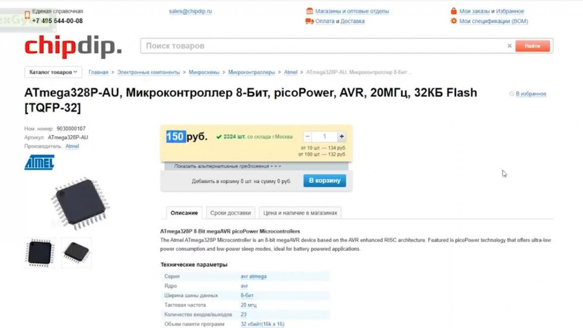
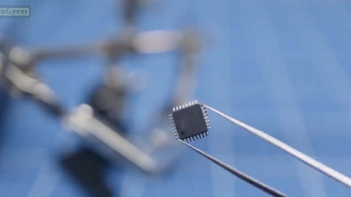
- and of course Arduino nano, which will manage all this iron.
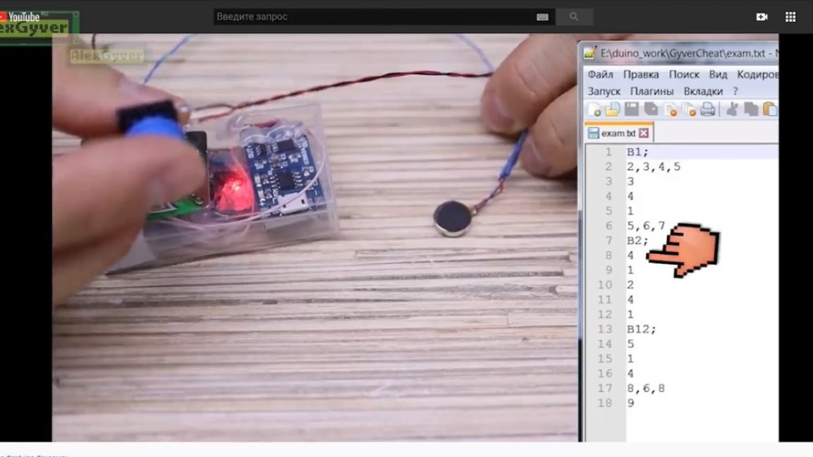
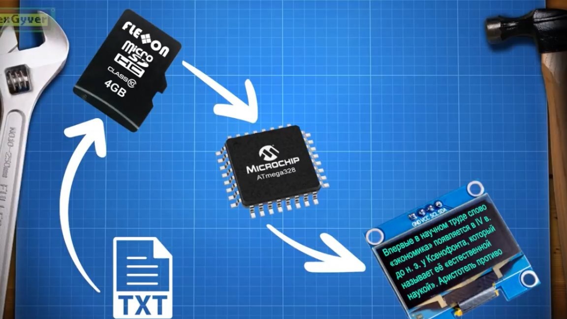
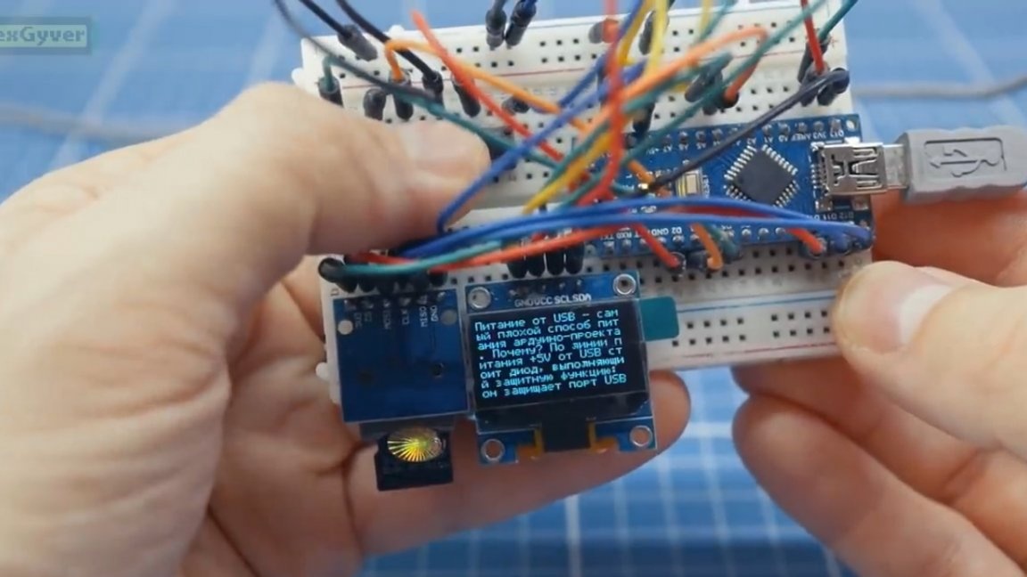
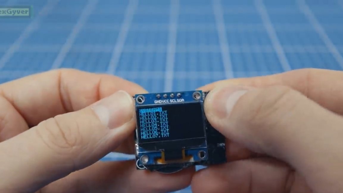
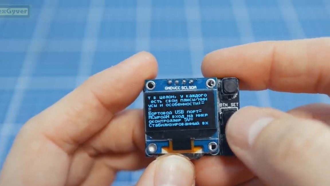
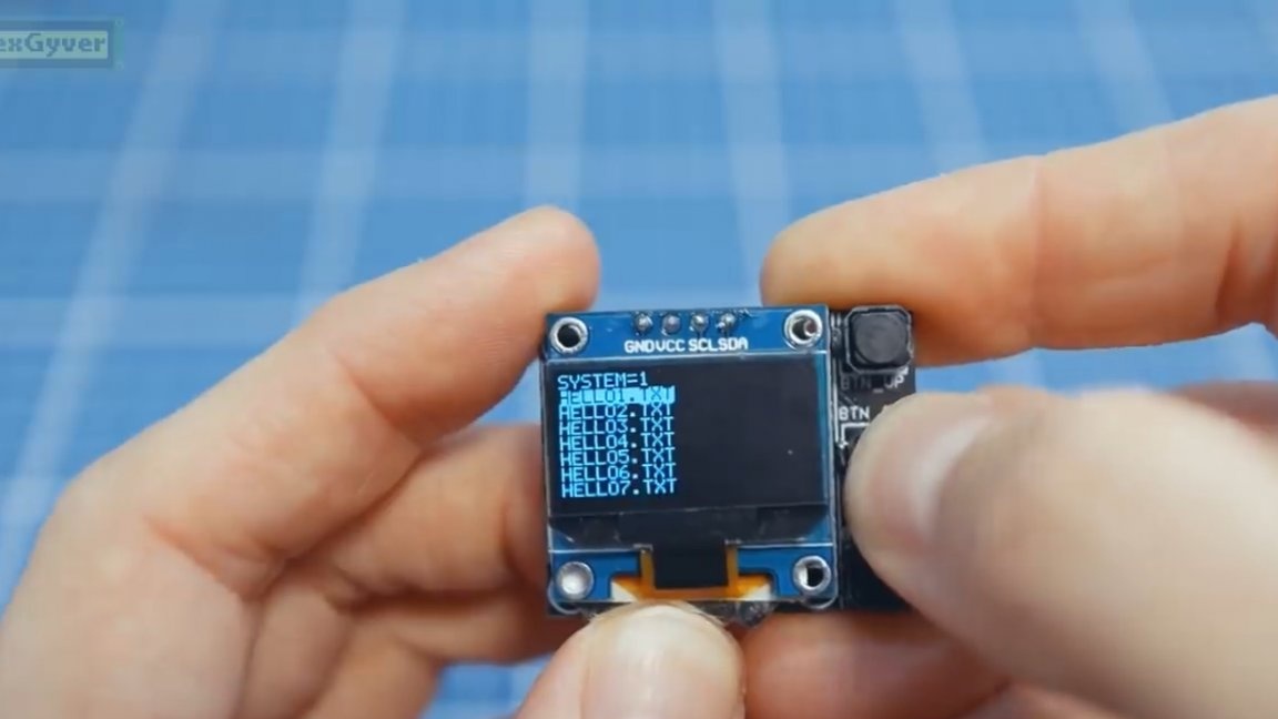
The idea is this: we drop any text in txt format onto a memory card, using a plain text file. The microcontroller will read the text from the file and display it.
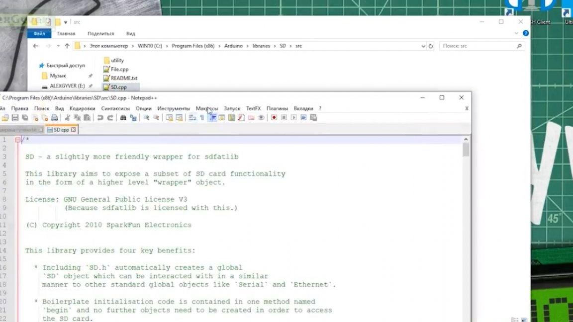
At first glance, the task seems quite simple, but in fact it is not quite so. The native library for working with a map of this type was written naturally by Indians for Indians, and the author decided to redo it a little.
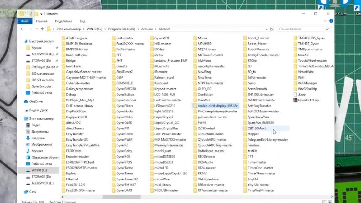
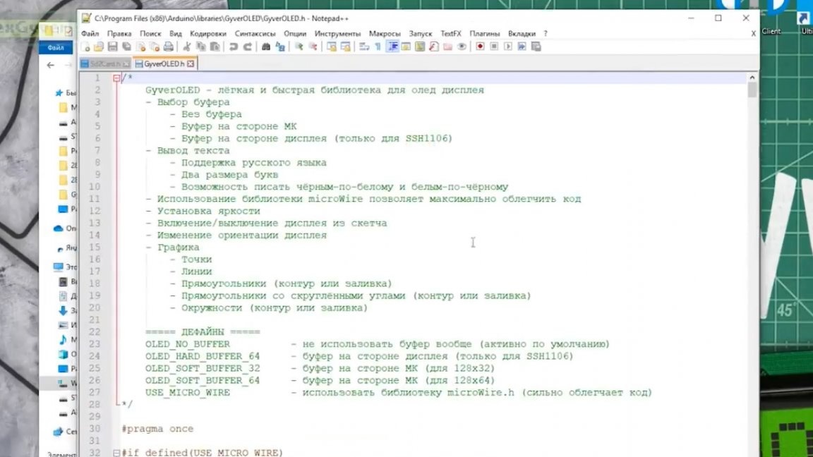
You can easily find many libraries for an OLED display on the network, but unfortunately they were written by the same Indians, and in this case, the author had to write his own, which will display data on the display without using a buffer on the side of the microcontroller, and plus to everything correctly display the Russian font.
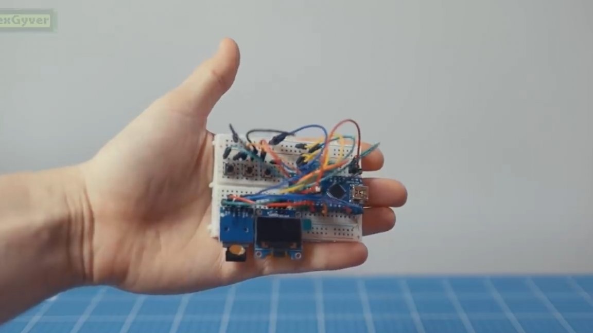
Here is the layout of our future device:
I think everyone agrees that there is nothing to hide such a cheat sheet for, it will not be trivial to use it for its intended purpose, without attracting too much attention to your person.
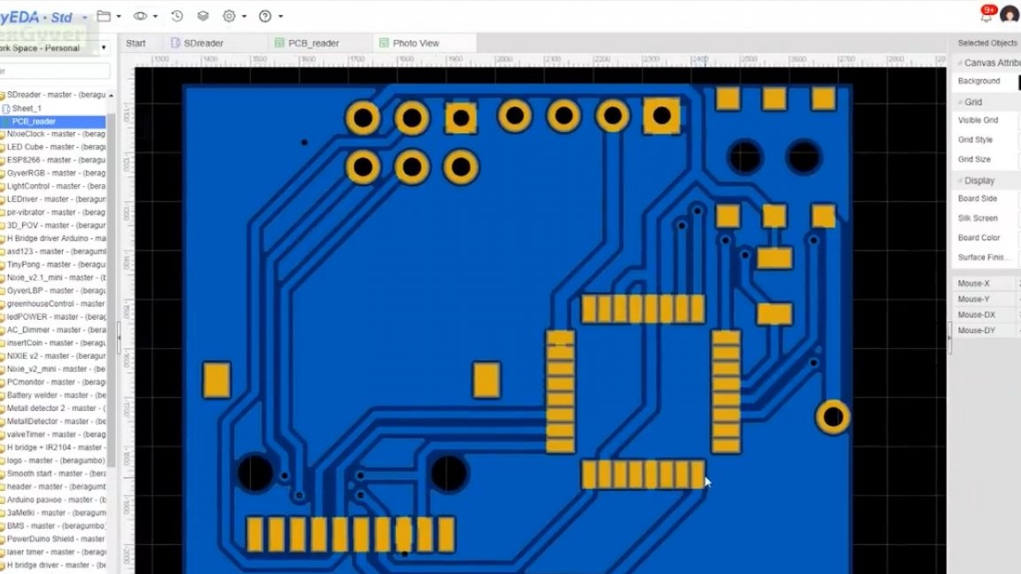
But we do know how to breed printed circuit boards, so that’s what we’ll do now.
The first step is to draw a circuit board. The author, as usual, divorced it in the online editor EasyEDA.
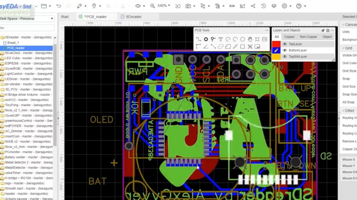
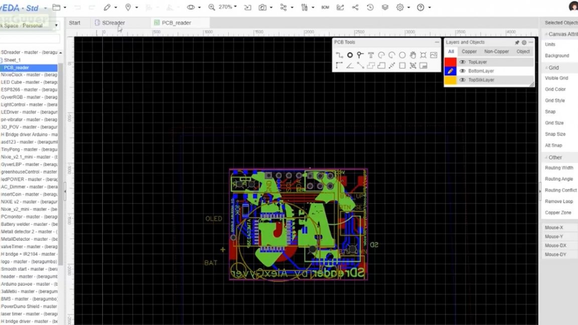
It looks like this Scheme of the future device:
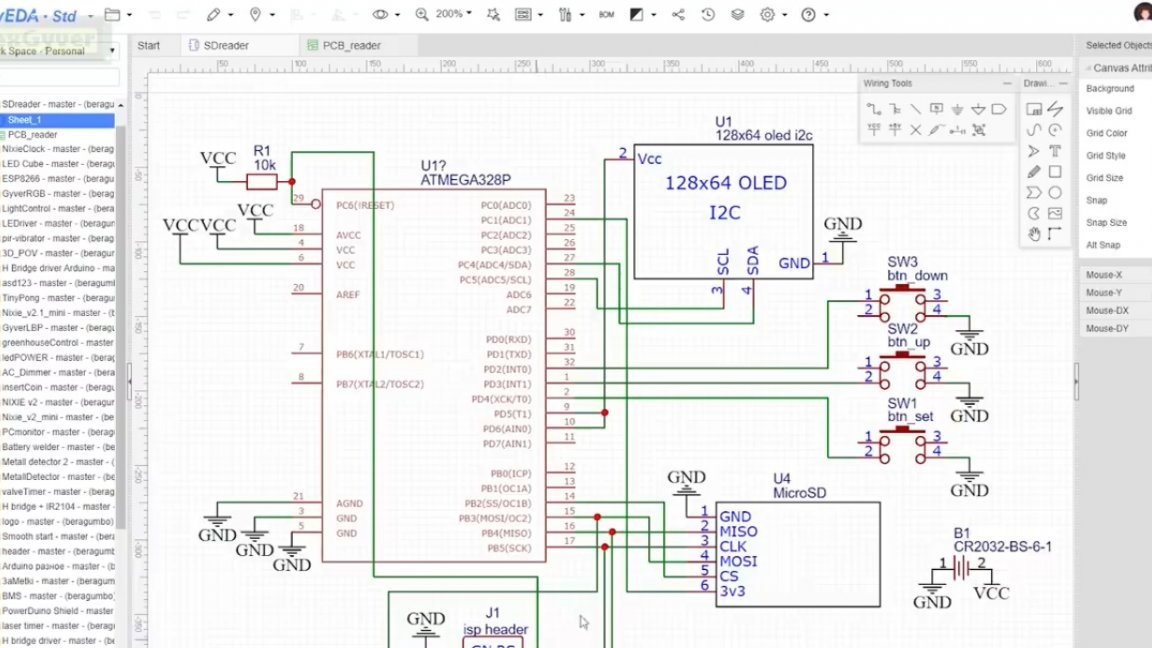
The diagram shows all the necessary components: a microcontroller, 3 buttons, a display, a microSD card slot, a battery, and a resistor, which is needed to tighten the reset pin for the duration of the chip firmware.
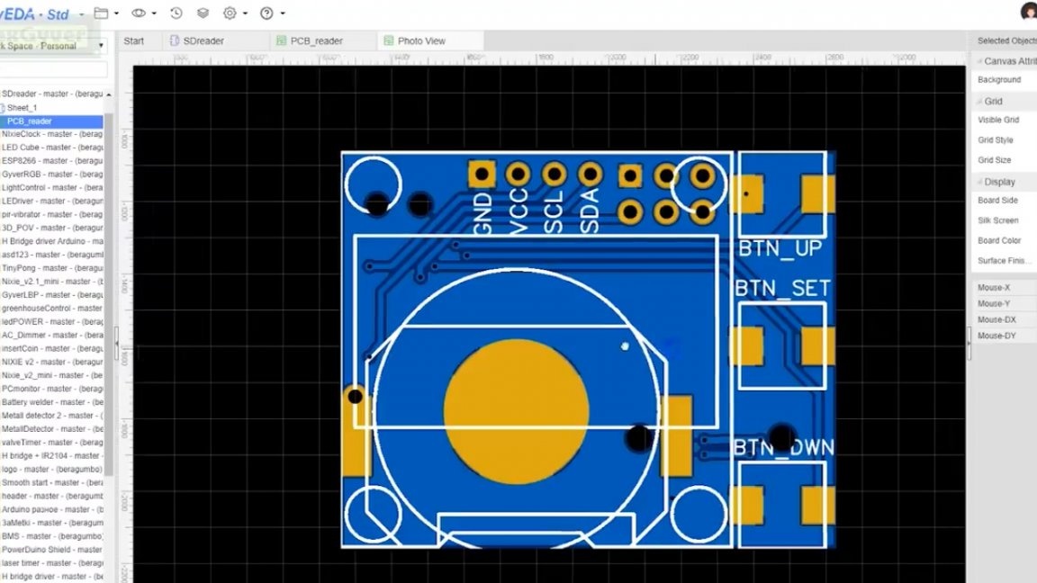
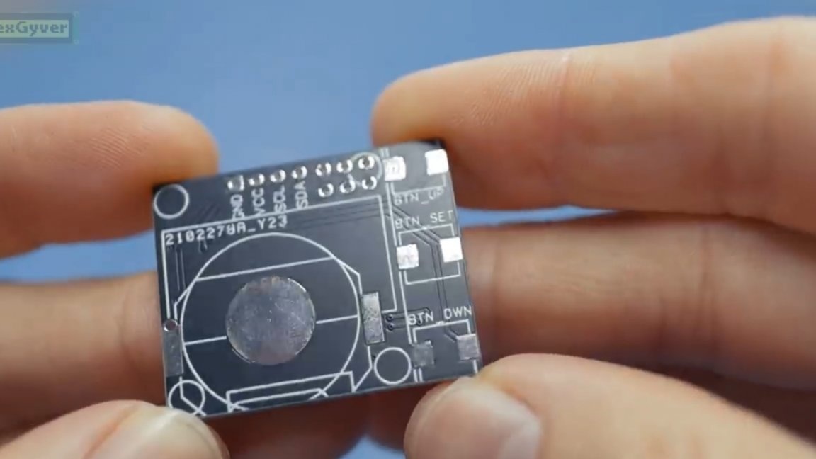
The main objective of the project is maximum compactness. For this reason, the author designed the board very carefully in the size of the display and 3 buttons.
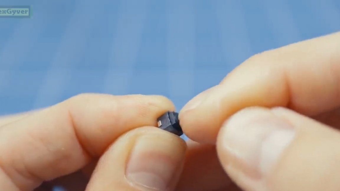
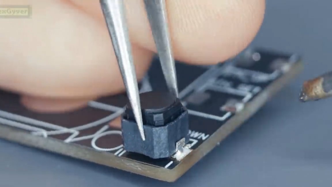
These buttons, by the way, are silent, very cool, and these are just perfect for our project today.
A cr2025 or 2032 format lithium-ion battery will be placed under the display, and the microcontroller itself, as well as an on / off switch, will be located directly below.
You can download the archive with the project HERE.
An important point! On board Arduino we have a 16 MHz clock generator and the microcontroller is configured to work with it.
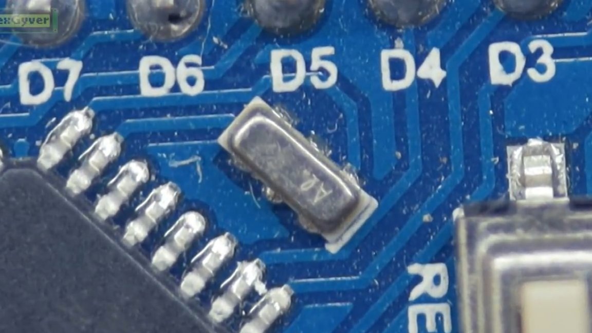
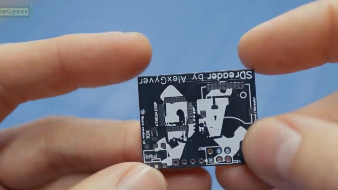
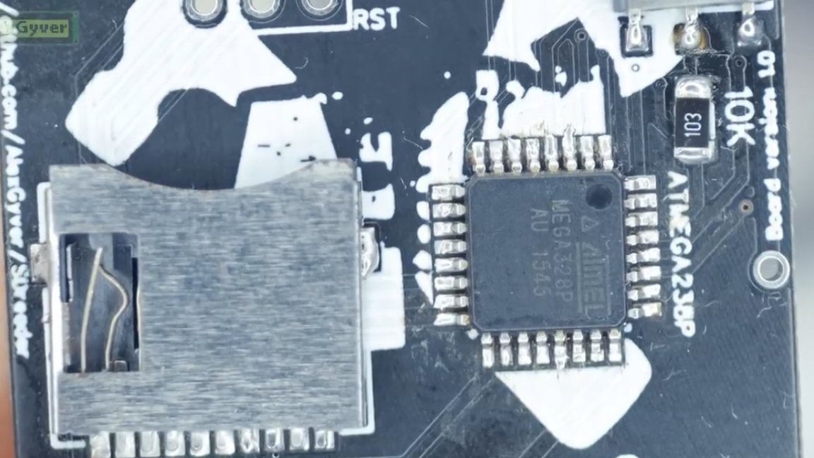
There is no generator crib on the board to simplify assembly, and the microcontroller is powered by an internal clock. For this to work, we need to configure the fuse for an internal clock source, or buy a bare ATmega328 chip, in which everything already stands as it should.
Then we need usbasp programmer, but you can also use another arduinka as a programmer, instructions are on the Internet.
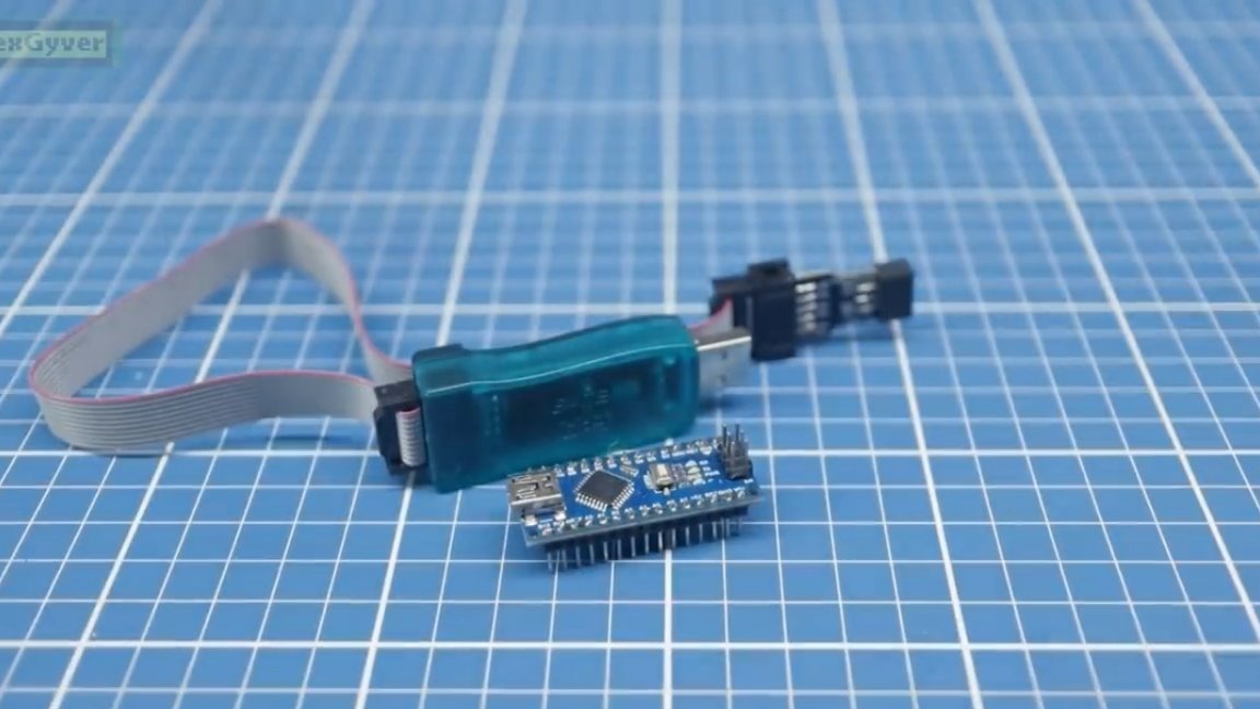
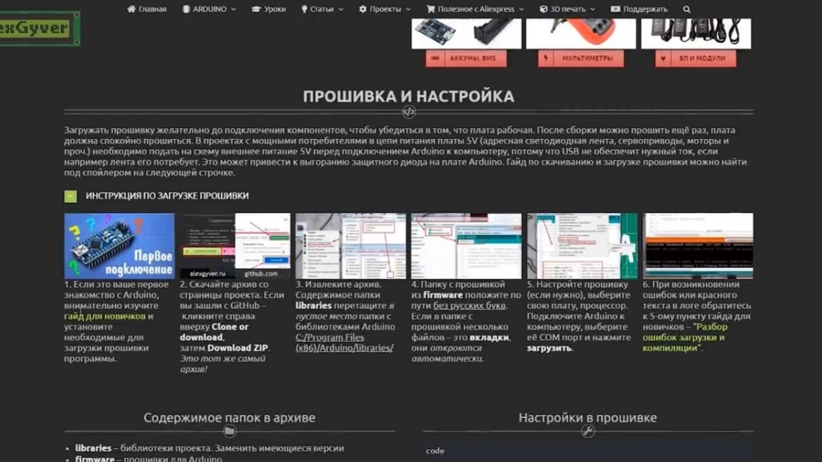
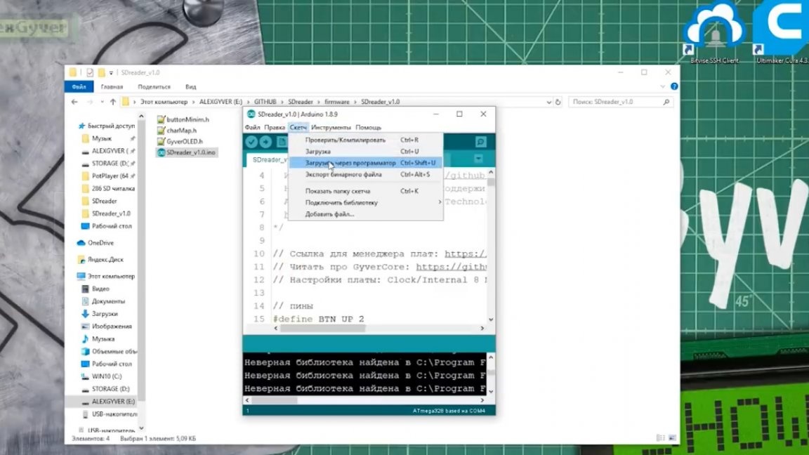
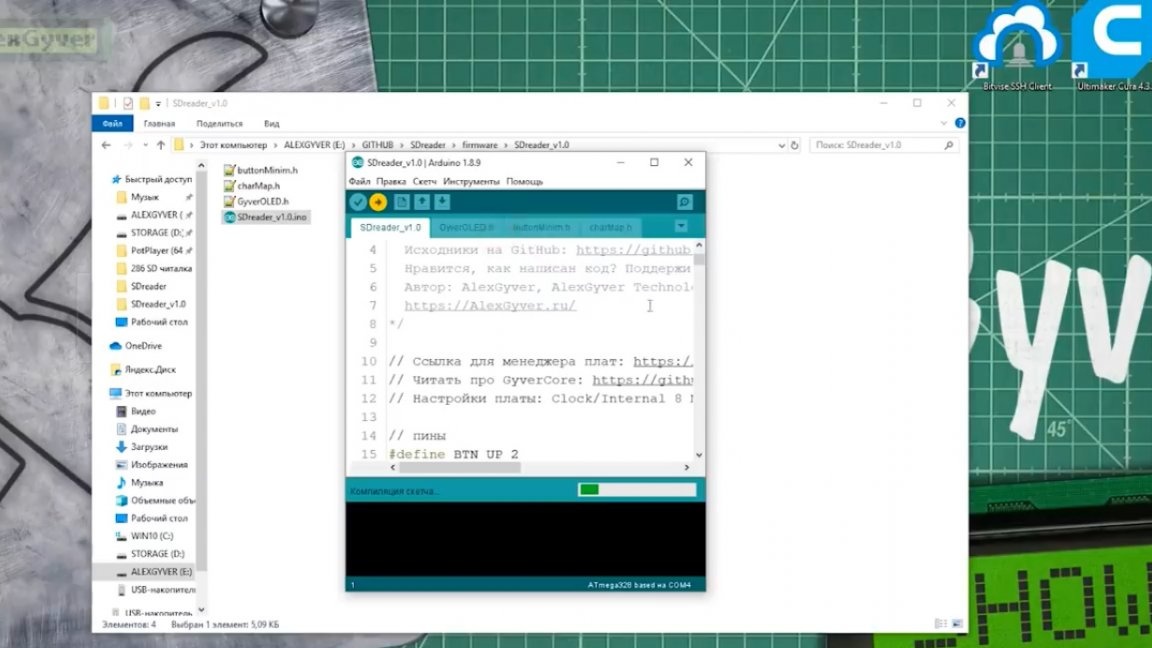
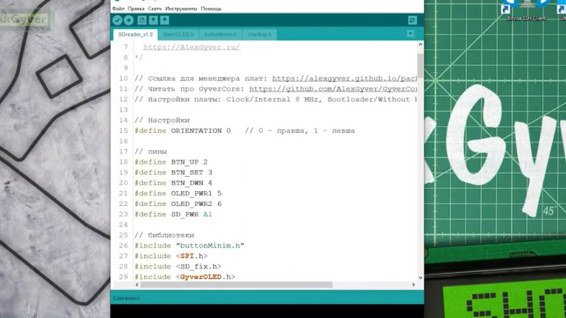
The procedure is as follows: first you need to open the firmware downloaded along with the project archive, then you need to install the modified gyvercore kernel, more details can be found on the author’s site.
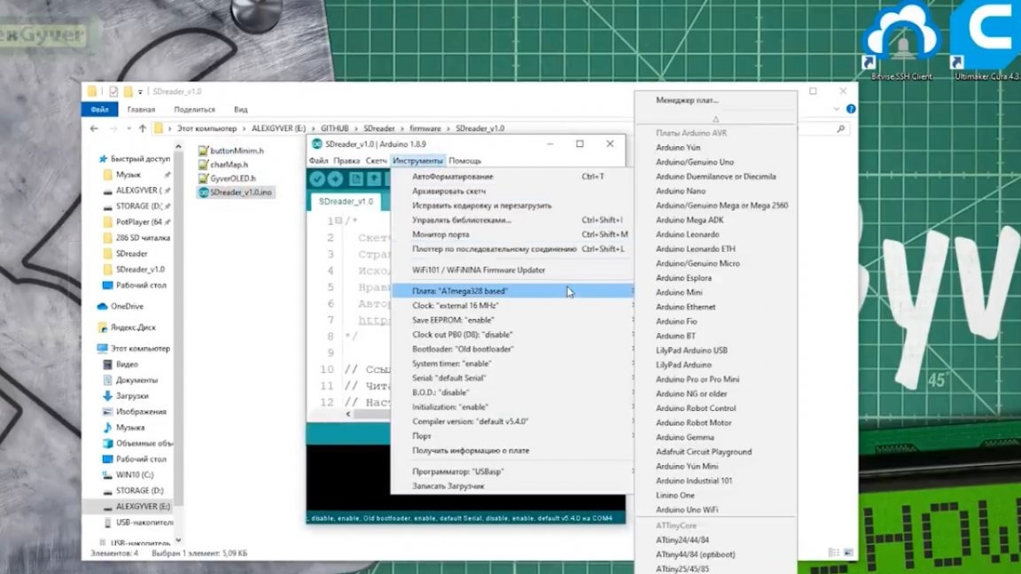
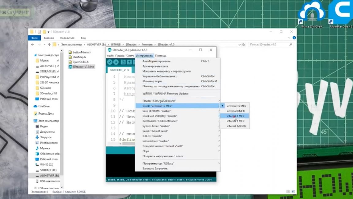
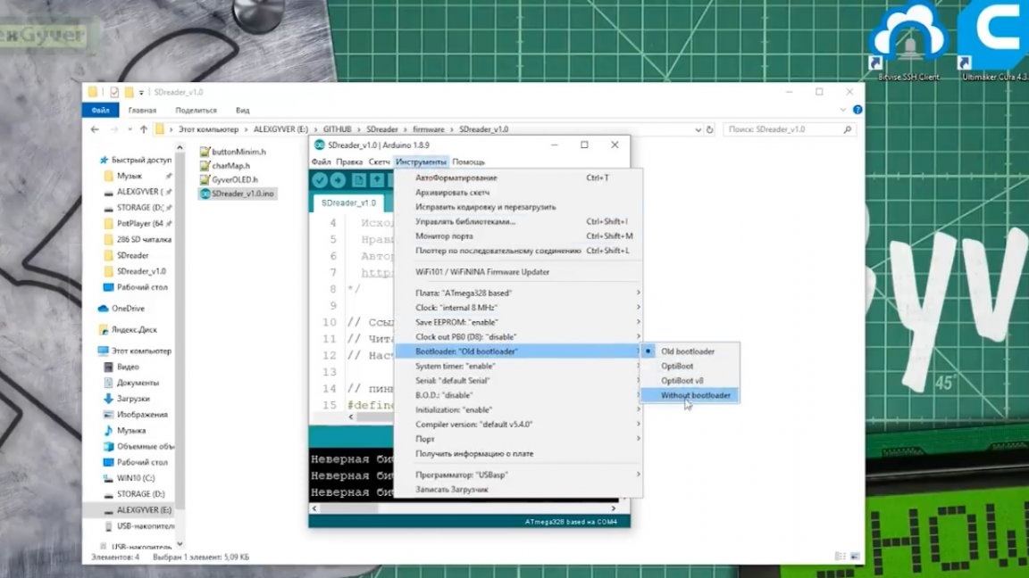
Next, select the internal 8 MHz clock source, select the bootloader “without bootloader”, this will speed up the inclusion of our device.
And click "record bootloader."
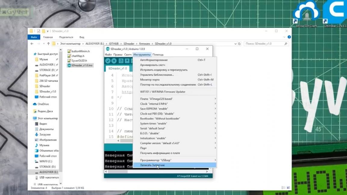
Next, click “sketch” - “download via the programmer” and the firmware is loaded into the chip.
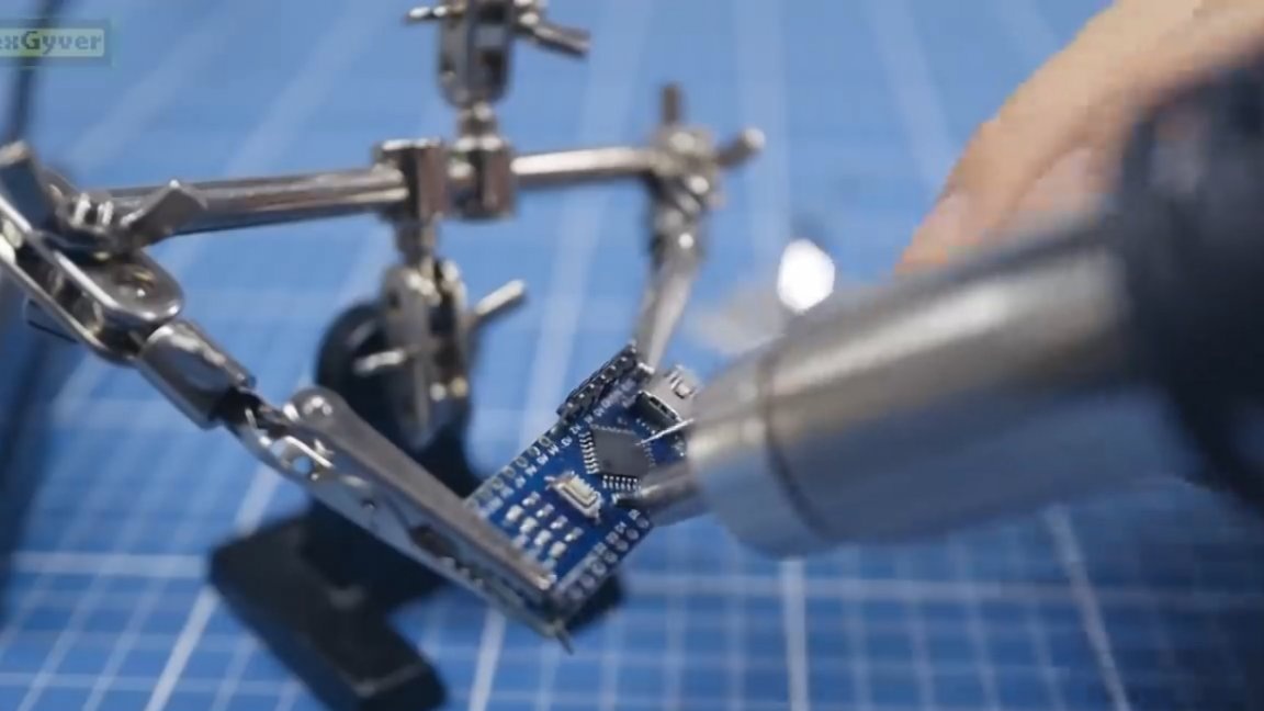
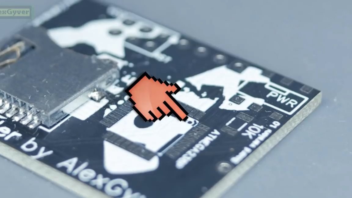
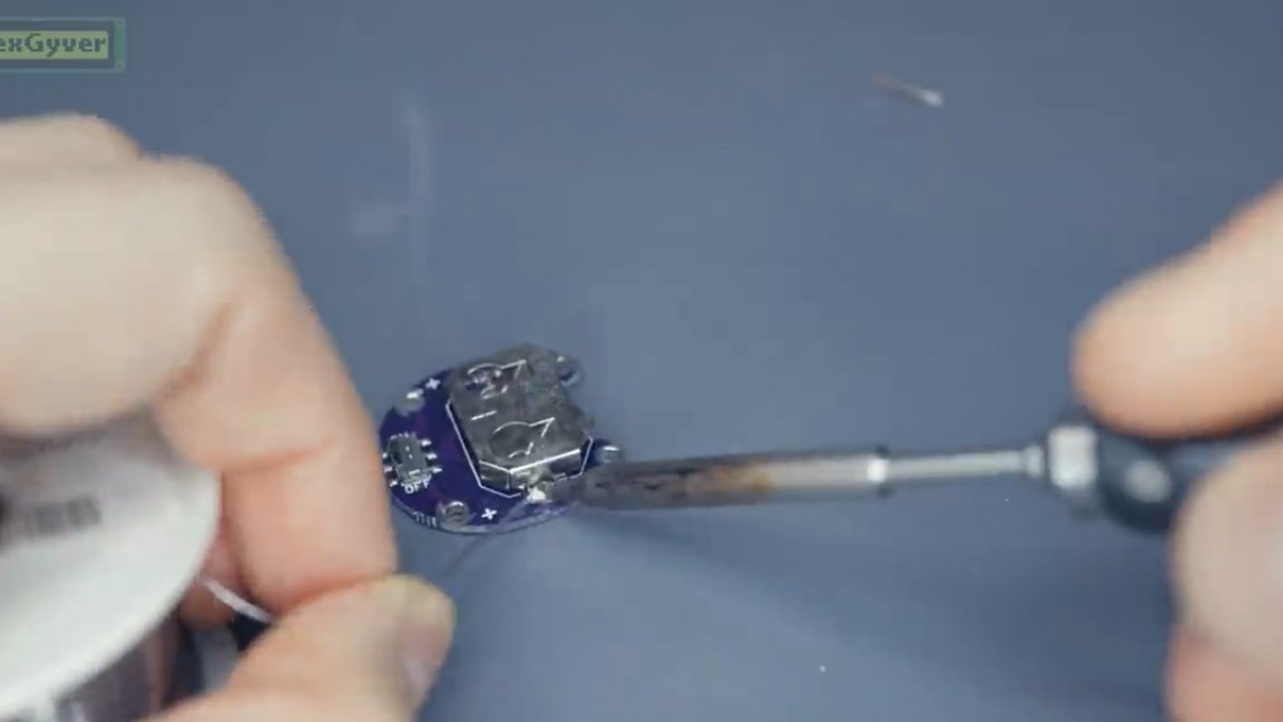
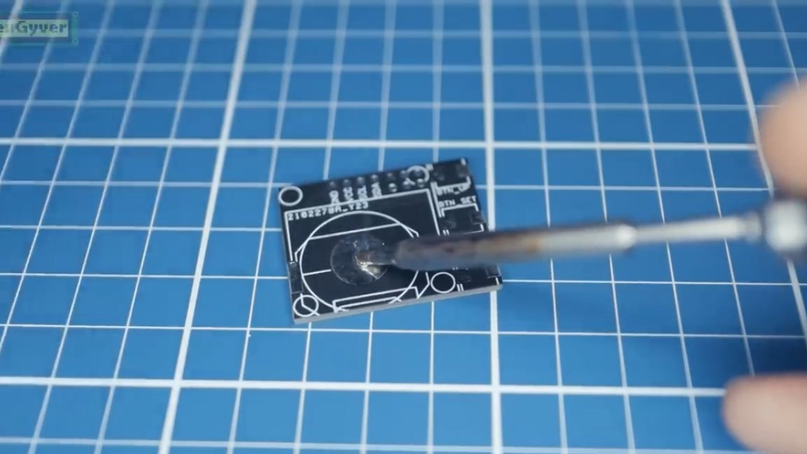
The next step is to take a hair dryer and “blow off” (solder) the microcontroller from the board. I repeat, you can take a bare stone, if you do not have a hair dryer and already solder it to the board.
The memory card slot must also be removed from the module. Or look for where you can buy one piece without a fee.
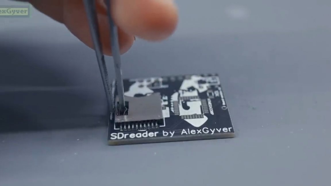
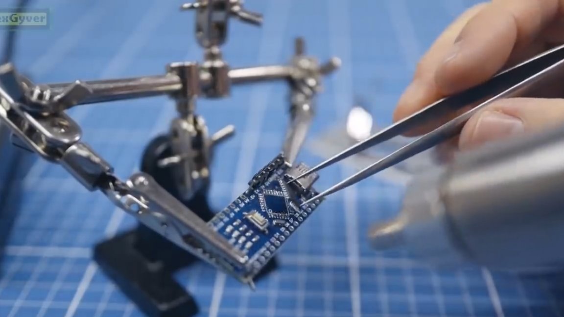
Here is the point, combine it with the point on the chip.
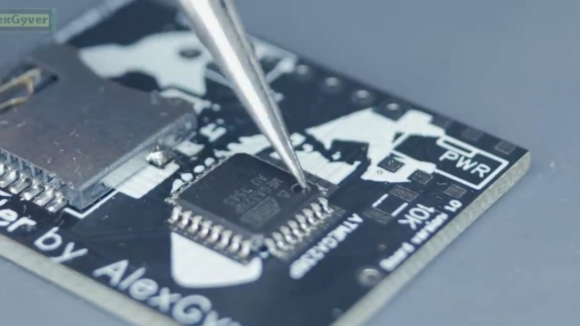
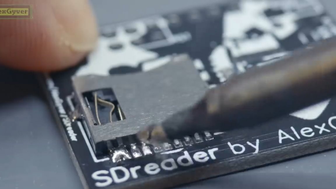
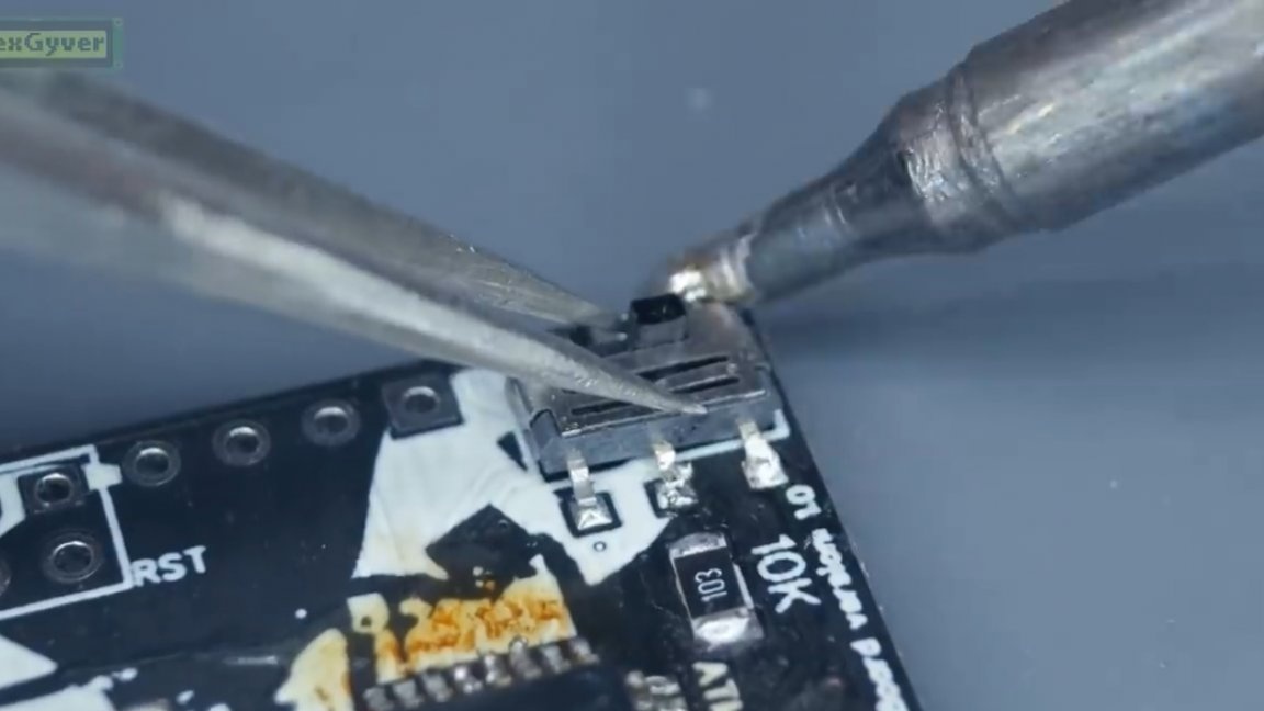
Next, fix a pair of legs and solder.
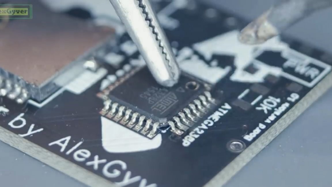
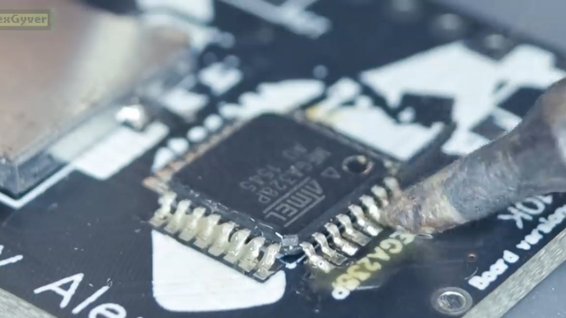
The chip body is quite small, but everything seemed to work out fine. Next, solder off the battery compartment and switch.
Then we solder these components to a new board.
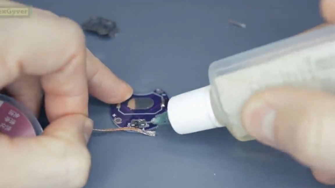
The next step is to thoroughly rinse off the flux residues, for example, with a Kalosha cleaner.
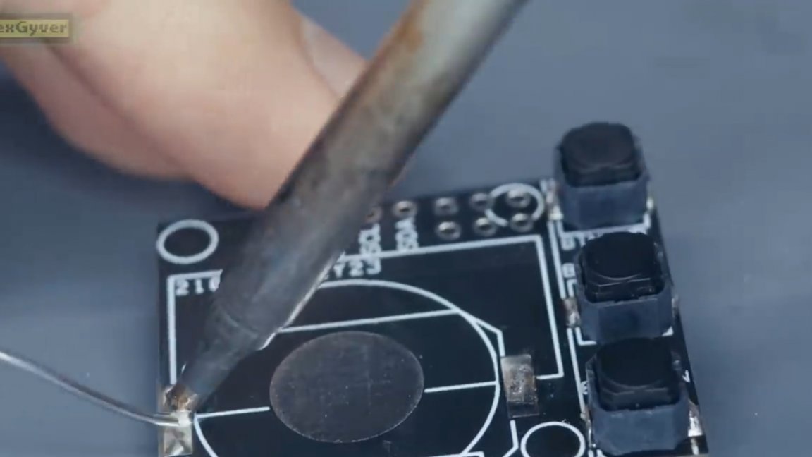
With the bottom side of the board finished, proceed to the other. The first step is to slightly thicken the battery pad. This is necessary in order to have normal contact, since the batteries are different, some have a thickening on the minus side, and some do not have such a thickening, and they will work poorly.
Next, solder the buttons and the battery compartment.
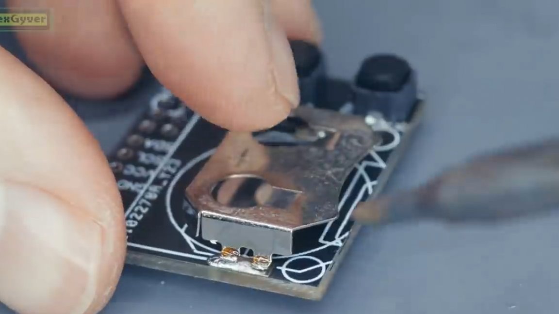
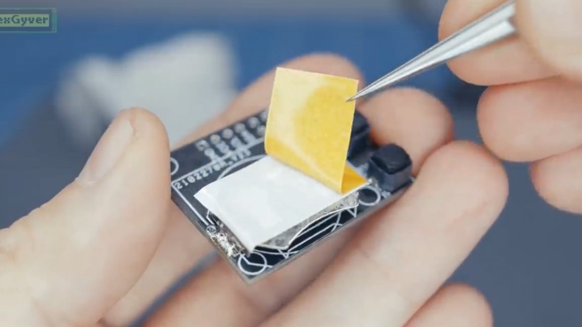
Then it is advisable to stick double-sided tape on the battery compartment, but in extreme cases, the electrical tape will come off.
This is necessary so that the contacts do not close on the display.
The next step is to solder the display.
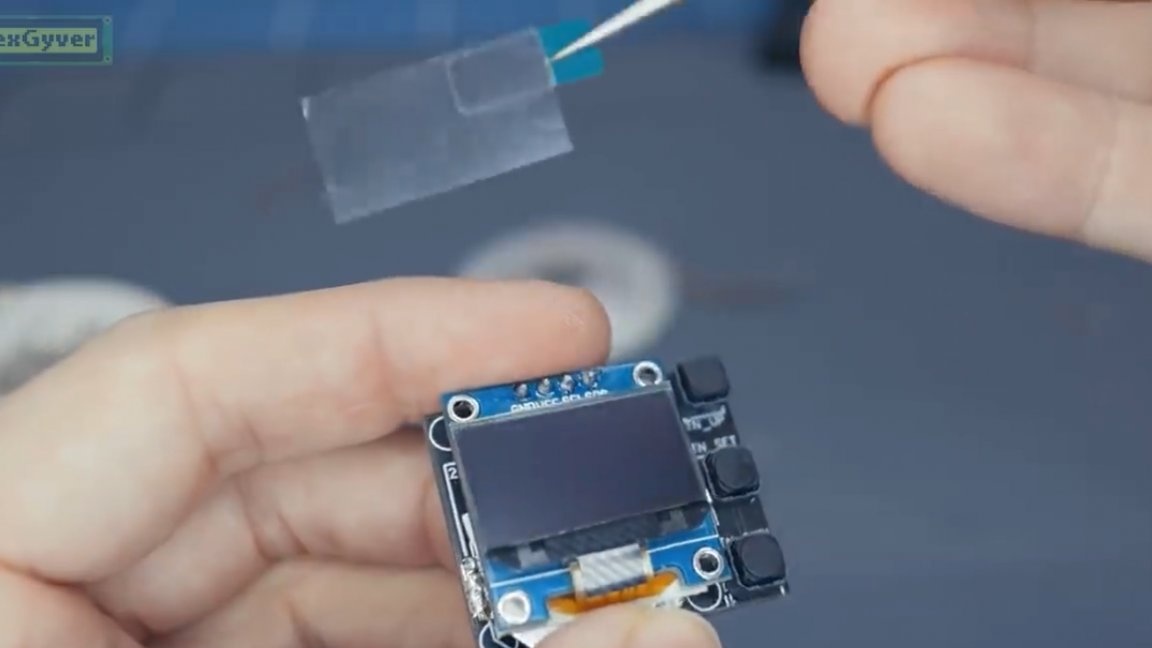
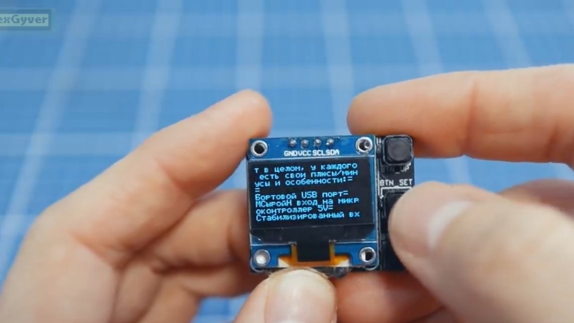
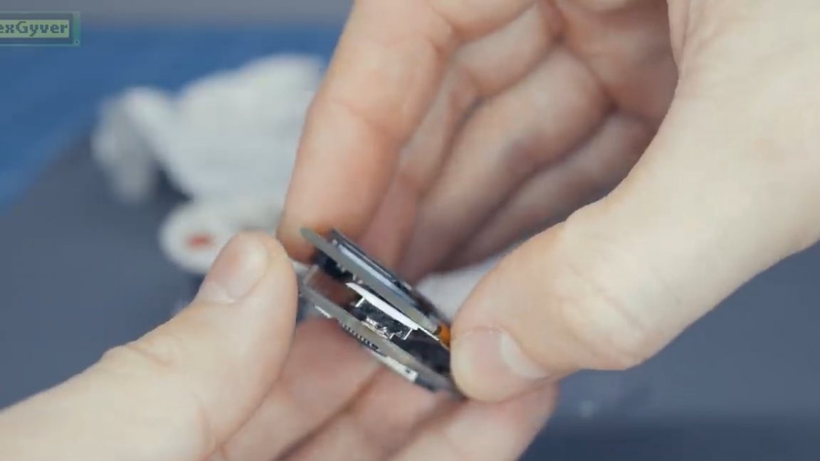
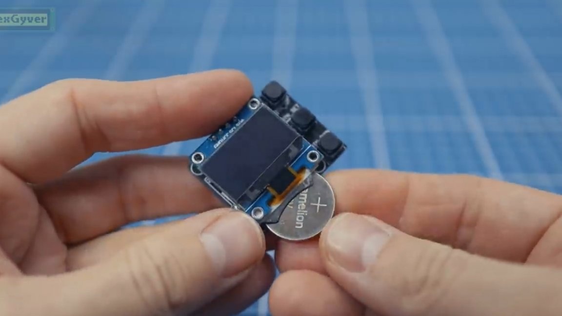
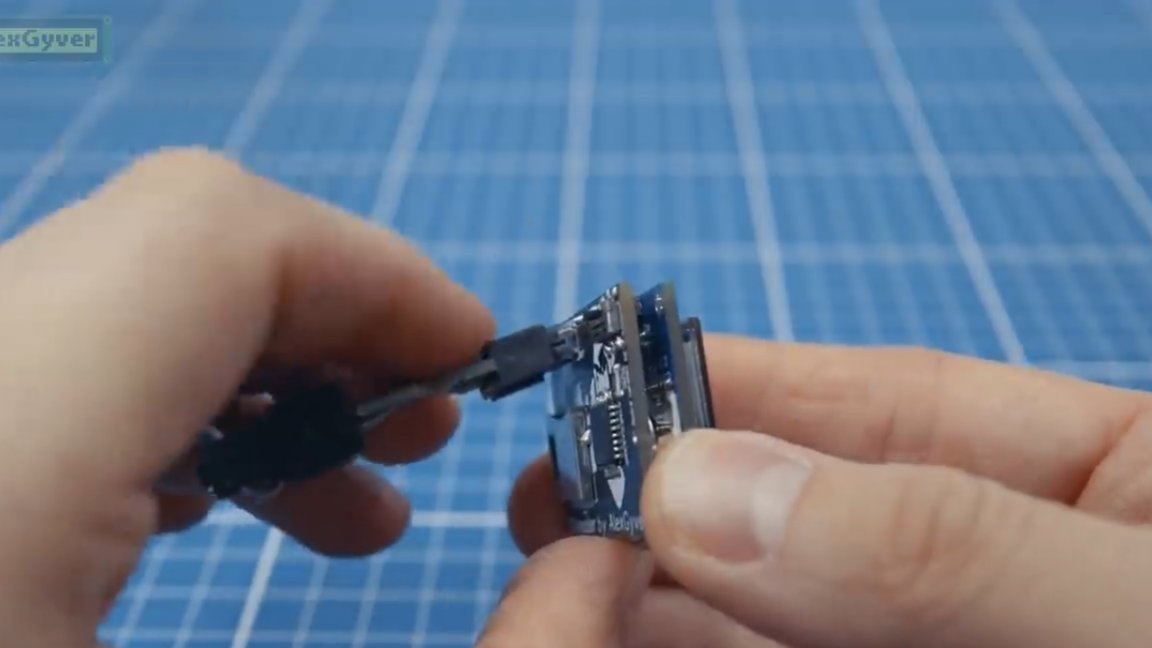
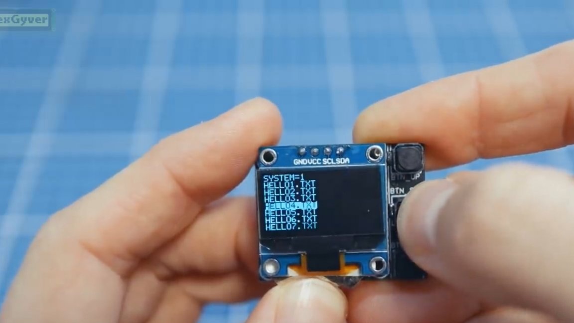
Well, that's all, our high-tech spur is completely ready. We insert the battery (plus up), a memory card and turn on the device.
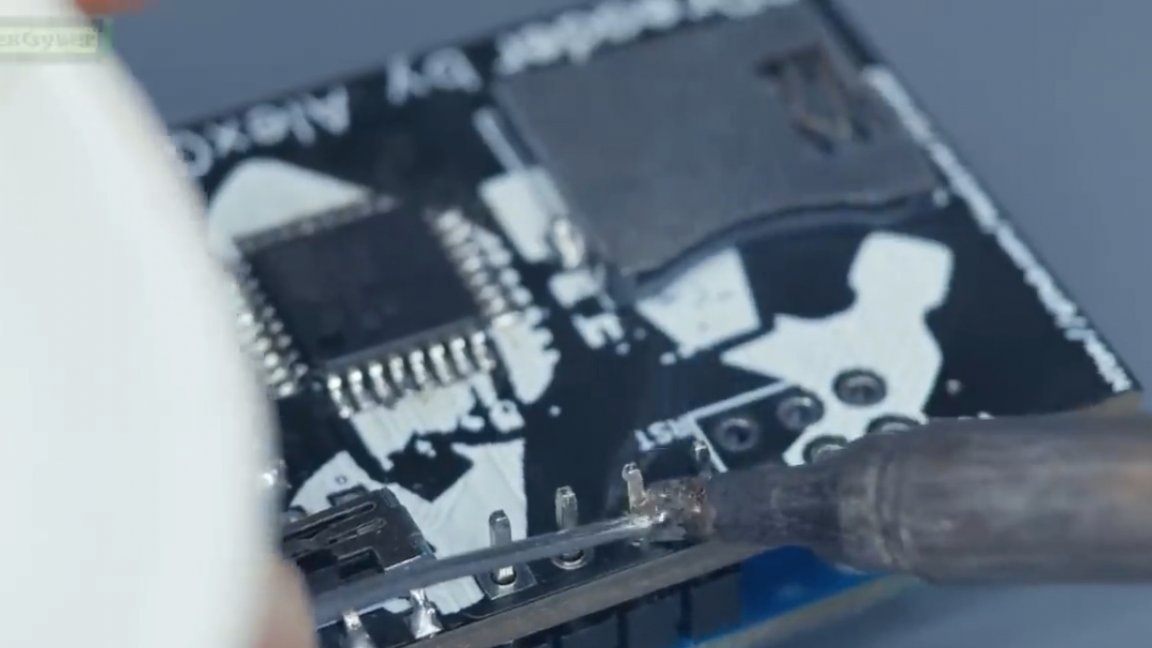
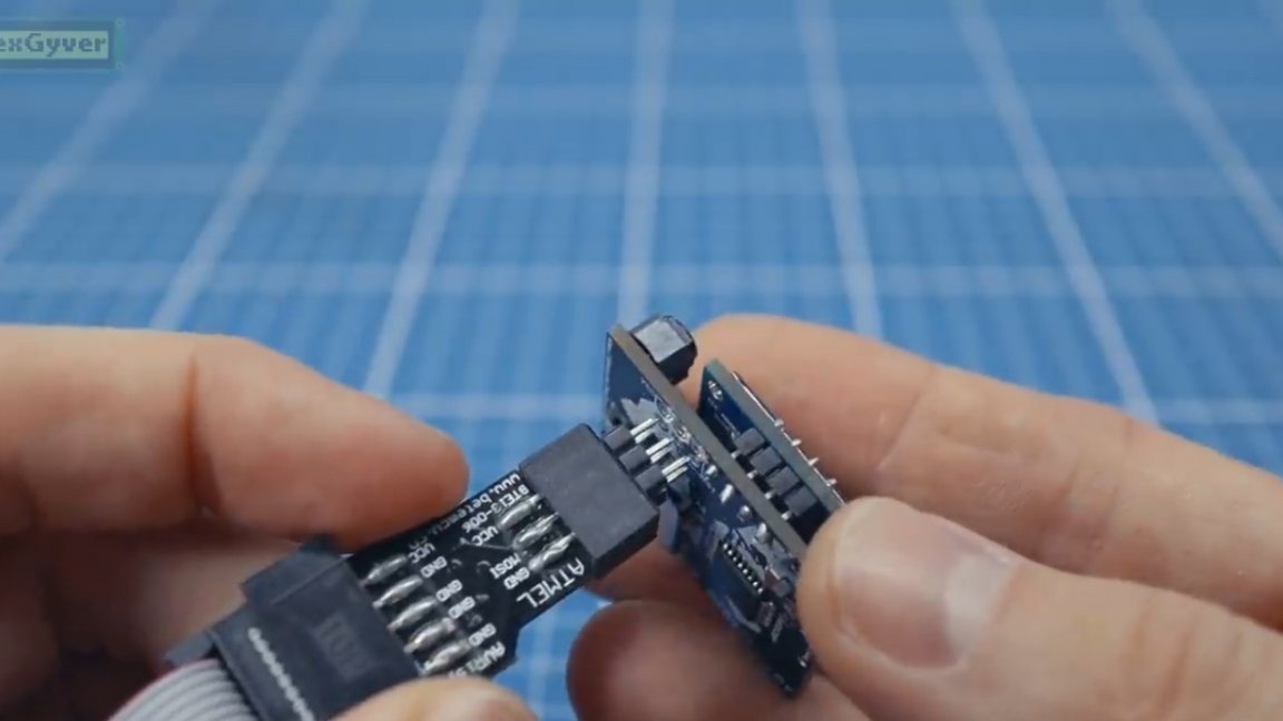
As you can see, everything works! To reflash a device, the first thing you must do is turn it off. Then we remove the memory card and insert the programmer block with the VCC pin in the upper left hole and tilt it a little, like this:
Let's go back to the firmware file. Here you can configure the right-handed mode and left-handed mode (it affects the orientation of the screen and the direction of the buttons).
The middle button - select and exit sleep mode, another 2 buttons - this is up / down to scroll through text and files.
To exit the file reading mode, press and hold the selection button.
As a result, such a rather interesting device turned out, maybe someone will help in the delivery of useless items with unreasonably high requirements for memorizing the text.
That's all. Thank you for attention. See you soon!
Author's video: