

Good day to all. I bring to your attention my version of the alteration of the pedal module from the steering wheel for a computer for controlling power tools.
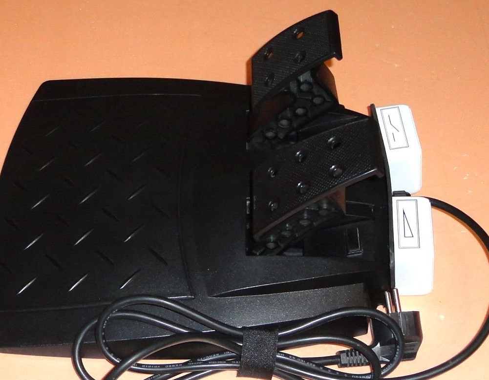
The idea was to use the pedal module in the design, the remainder of the steering wheel broken by the children for the computer (maybe the rest of the steering wheel will also work, I didn’t throw it away). Since there are two pedals in the module, I decided to make two independent control channels. The first channel has a load on / off function. The second channel has the function of smoothly controlling the load power until it is completely turned off.
In this design was used:
- GW-10VR steering wheel pedal module for computer.
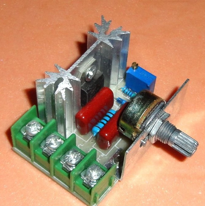
- Chinese dimmer 220v 2kW.
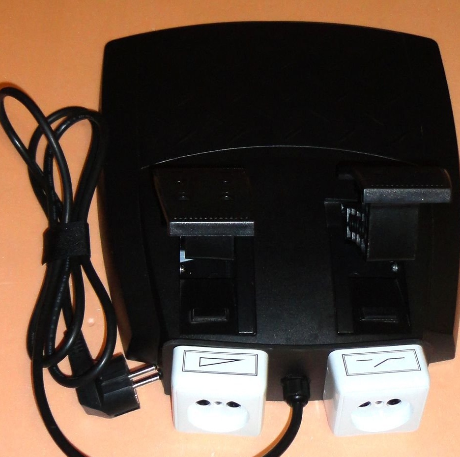
- Socket RO1 RA10-002 - 2pcs.
- Power cord with plug.
- Microswitch type RWA-401 - 2 pcs.
- Cable gland PG-7.
- Fasteners M3, M4.
- Scrap plastic.
Of the tools used:
- Drill.
- MFI type "Dremel".
- Soldering iron.
- Thermo-glue gun.
- Scissors for metal.
- Screwdriver, wire cutters, etc.
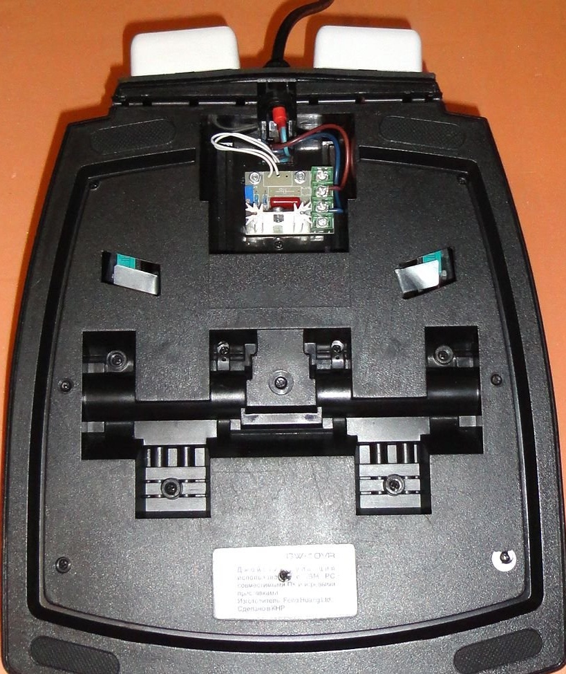
The pedal module was just a find, because in its design, it has a ready-made gear solution from the pedals to the variable resistor shaft.
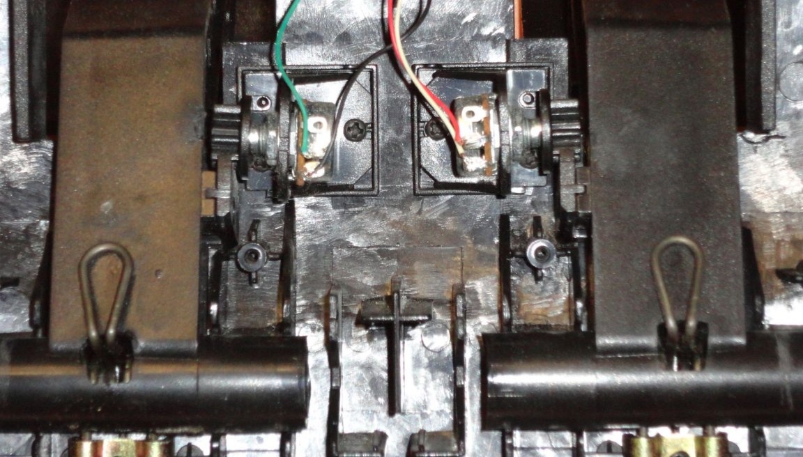
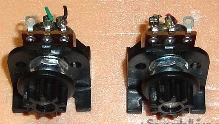
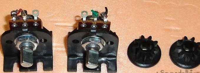
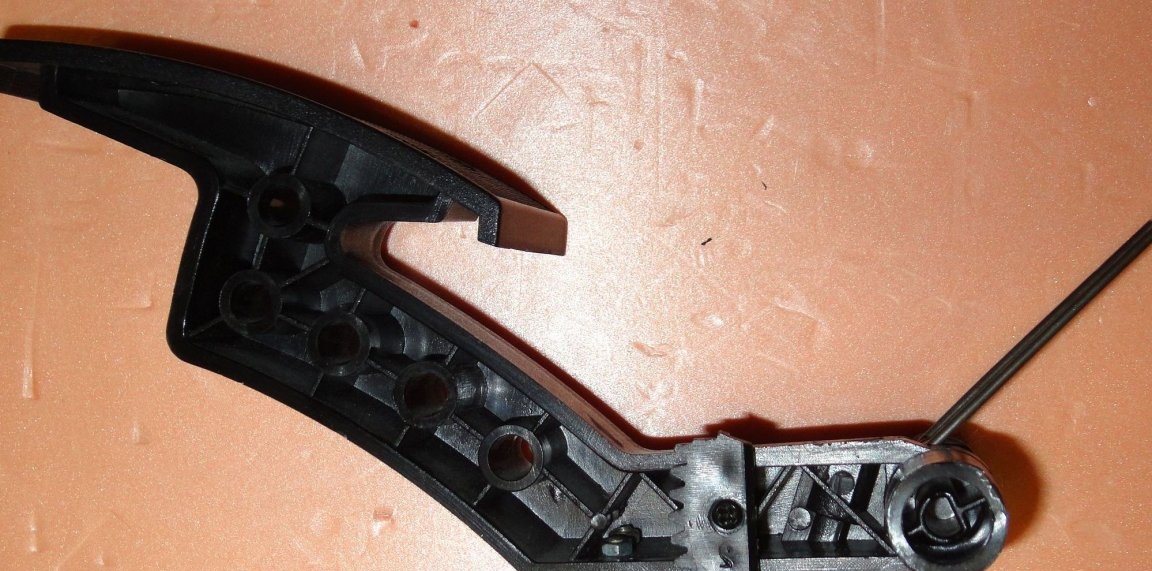
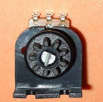
In the design, the variable resistor was replaced by 500 kOhm (was 50 kOhm). Since a suitable variable resistor with only a round shaft was found in the stash, I had to grind the chamfer. A plastic wedge is inserted into the cut.
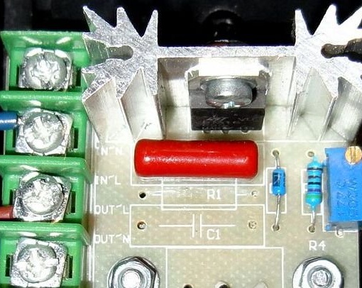
Usually in my designs I use my own dimmers, which are made for the design features of the product. Here I decided to use a ready-made Chinese dimmer (I was lying idle for a long time) which had to be slightly “lightened”, because he works in a pulsed mode and working with a power tool that has its own electronic adjustment blocks, the correction circuit R1-C1 only interferes. Overheating of the resistor R1 occurs (tested in practice). Therefore, R1 and C1 were removed from the board. The heat-conducting paste KPT-8 was applied to the radiator (initially completely absent).
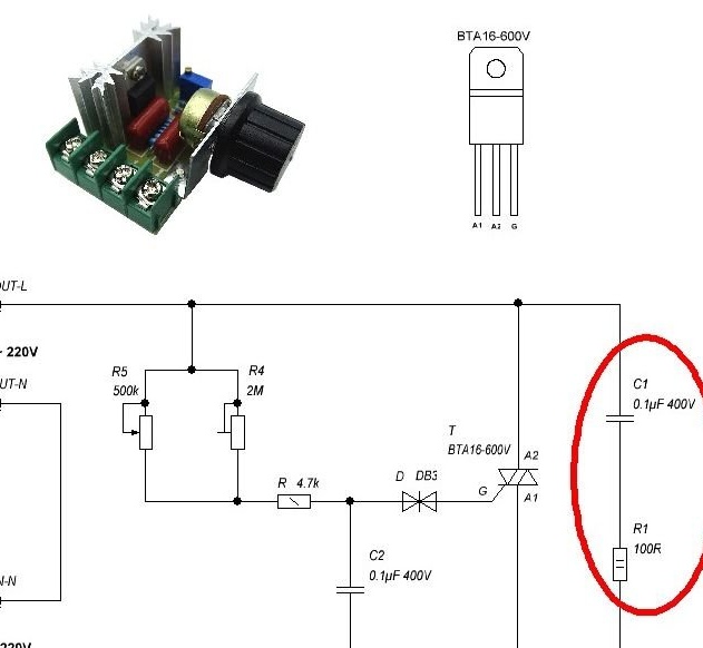
The numbering of parts on the diagram corresponds to their numbering indicated on the board.
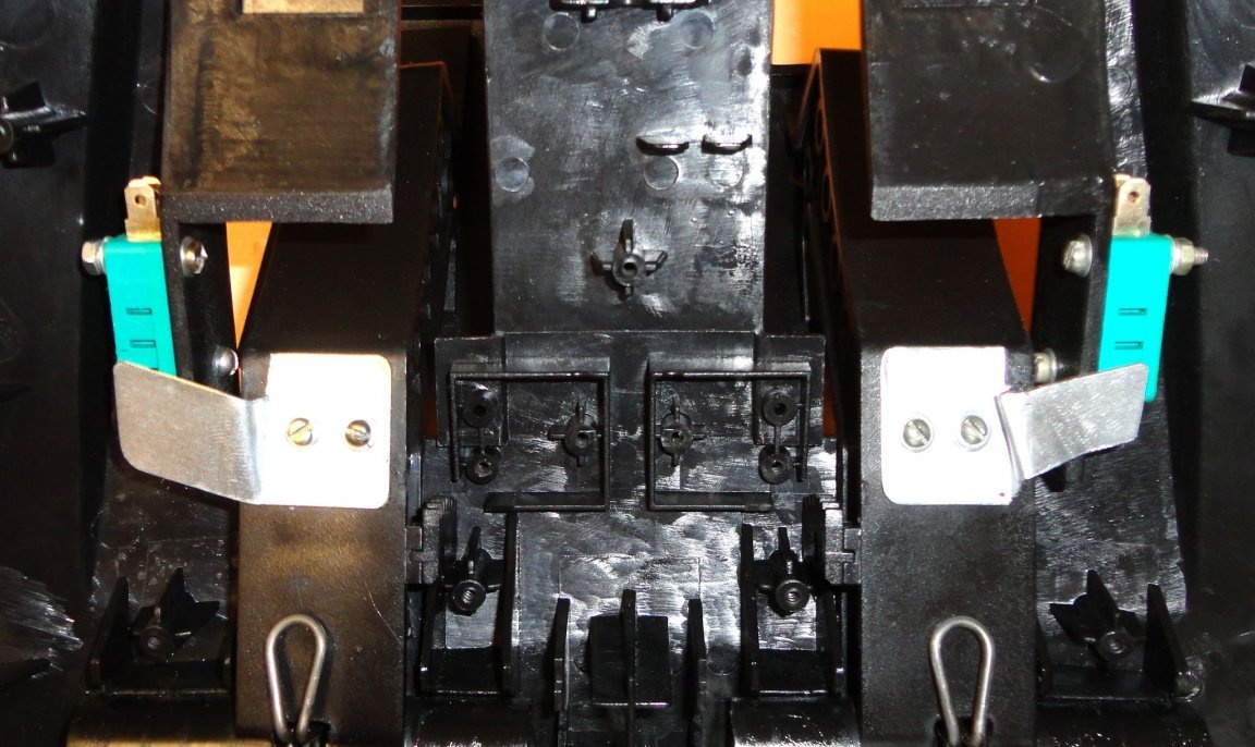
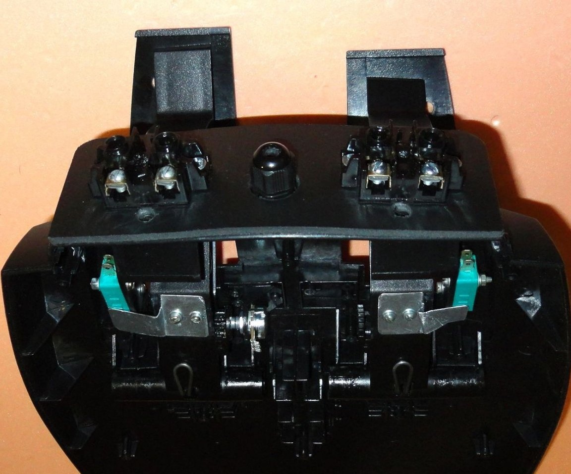
Microswitches are fixed in the housing with M3 screws.
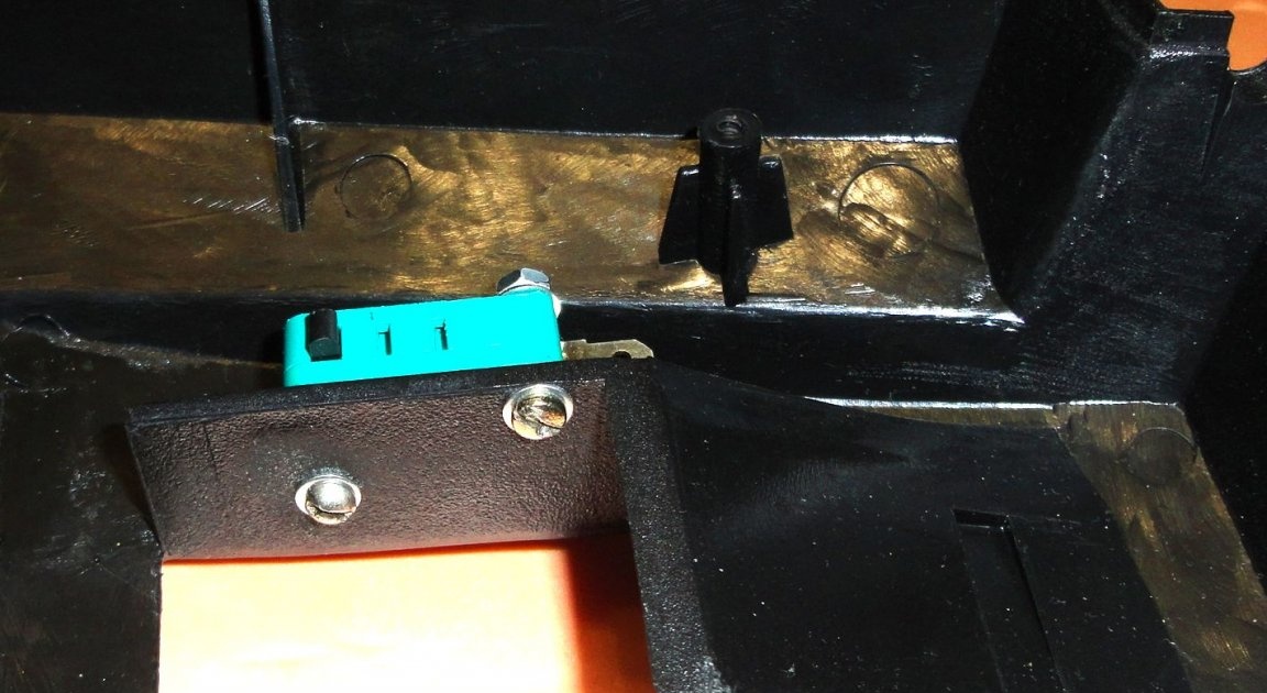
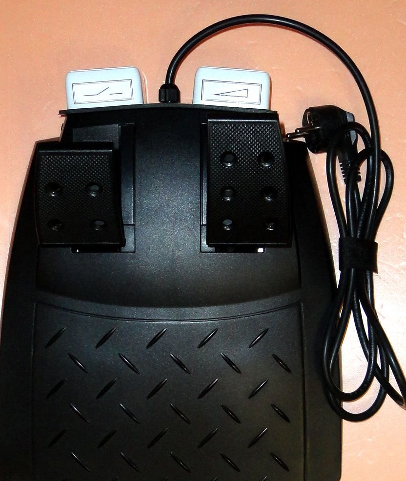
Metal plates are mounted on pedals with M3 screws.
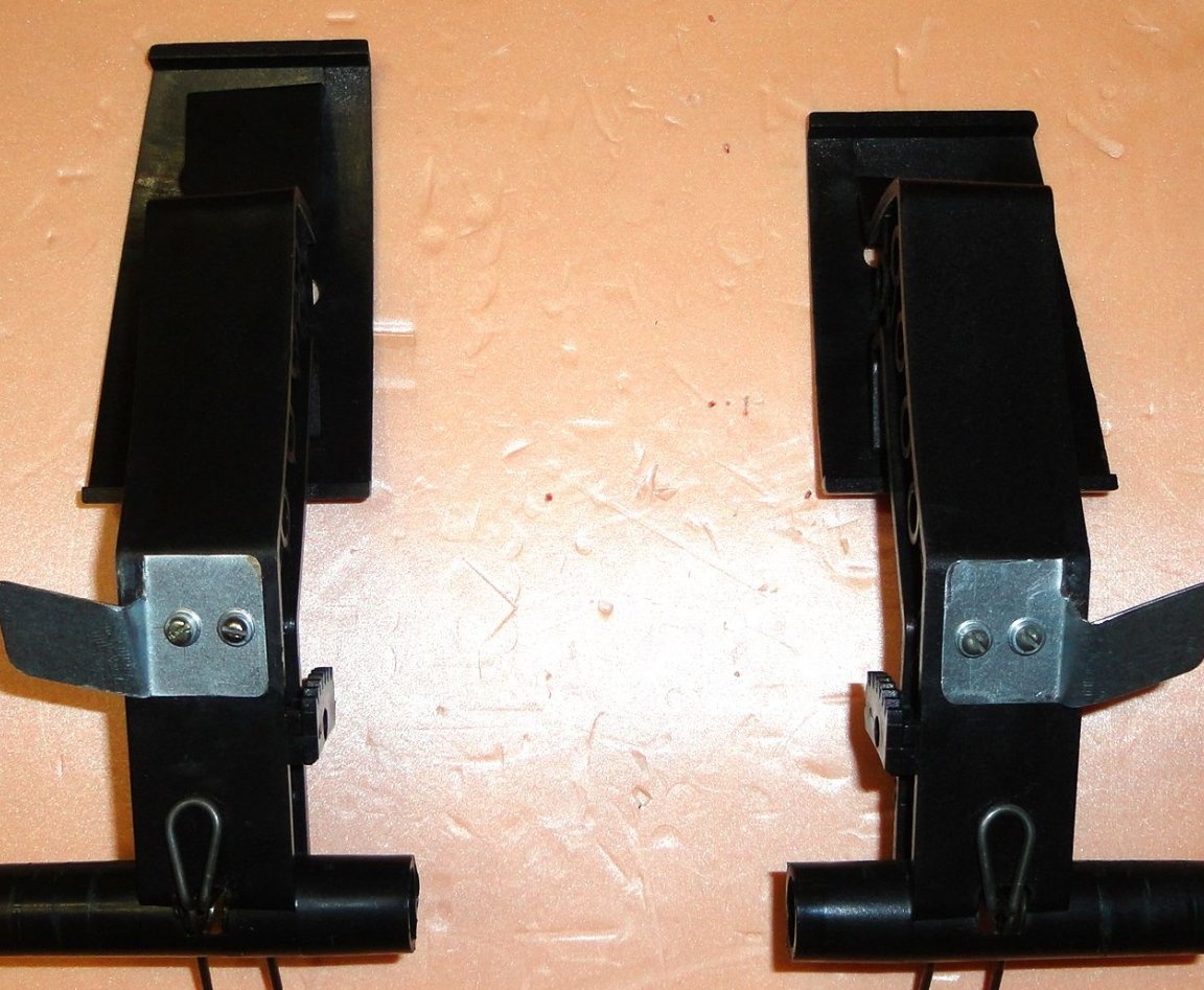
After installing the pedals in the housing, the plates were adjusted in place.
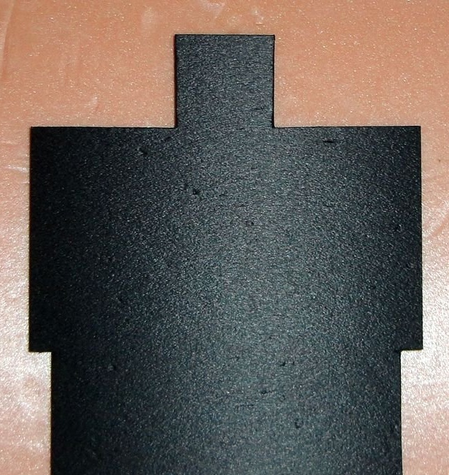
Since the sockets go beyond the dimensions of the case, to protect them from debris, the back panel was cut out of soft plastic for them.
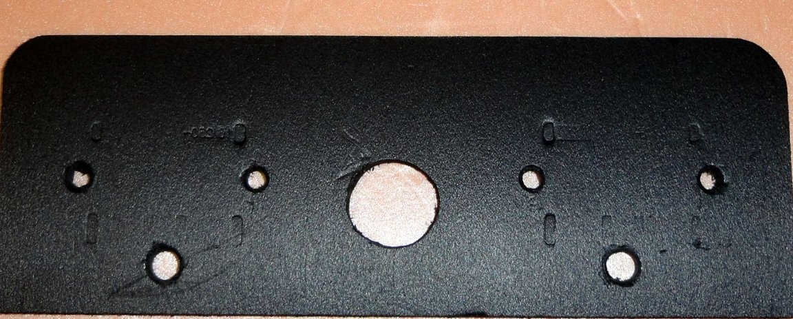
The base of the outlets is fixed to the case with M4 screws.A cable entry is installed in the center.
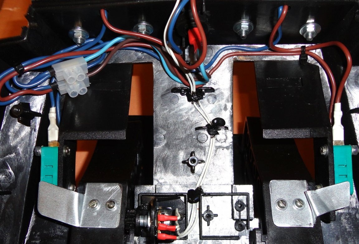
The network cable is connected via the terminal strip (for easy replacement). Microswitches are connected using knife connectors, contacts that are closed when the button is pressed are used. Because full pedal travel does not provide maximum rotation of the variable resistor shaft, then when it is mounted on the housing, the gear is mounted so that when the pedal is fully depressed, the maximum resistance value (500 kOhm) is. With the pedal fully depressed, the resistance is 27 kOhm. This range is enough for normal operation. There was an idea to connect a reed switch in parallel with the variable resistor R5, and attach a magnet to the pedals, setting the response distance with the pedal fully depressed. But so far I have no need for this. The offset of the adjustment range with the tuning resistor R4 is quite enough.
The power wires are fastened together with plastic ties, the wire from the variable resistor is fixed with hot-melt adhesive. This avoided the clamping of wires during assembly of the housing.
The power wires are fastened together with plastic ties, the wire from the variable resistor is fixed with hot-melt adhesive. This avoided the clamping of wires during assembly of the housing.
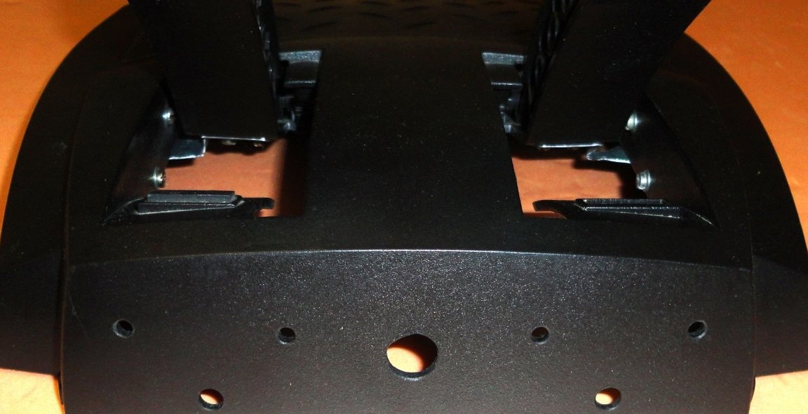
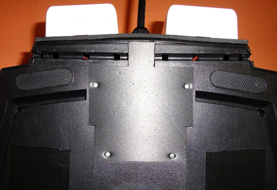
In the lower part of the body had to cut holes. They do not allow metal plates on the pedals to rest against the lower part of the body when the pedals are fully depressed. As a result, the pedals rest solely on the rubber stops on the upper part of the body. At the same time, metal plates do not reach the outer edge of the lower part of the body a little (by 1-1.5 mm).
The dimmer board is fixed to the bottom of the case through fiberglass gaskets on the M3 screws. The plastic stops for the dimmer cover are made of soft plastic with a thickness of 8 mm and are glued to the body with superglue (recessed by 3 mm). The cover is cut out of soft plastic 3mm thick. The cover is screwed with four small screws to the stops. The holes in the lower part of the case are sealed with repair tape (maybe later, I'll seal with thin plastic).
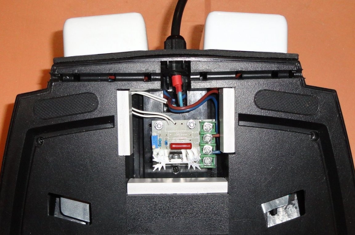
The socket of the first channel is connected to the network cable through a microswitch. The socket of the second channel is connected to the network cable through a dimmer and micro switch, which ensures its complete disconnection from the network with the pedal fully depressed.
The operation of the dimmer in this design was tested on the following power tools:
- Belt Sander Hammer LSM800 (800W - without built-in speed controller).
- Compressor spray gun Bosch PFS 3000-2 (650W - without built-in speed controller)
- Drill Makita HP1621F (650W - built-in speed controller).
- Drill Makita DP2010 (370W - built-in speed controller).
- MFI type "Dremel" Top Machine DM-130B (135W - built-in speed controller)
- The motor for the TUR 2 sewing machine (90W - straight, without a pedal), a slight adjustment of the adjustment range of the resistor R4 is required.
On instruments equipped with built-in soft starters and (or) constant electronics was not tested.
At 800W, the heatsink only heats up slightly. I think that with a load of 1400-1500W you will need a larger radiator. For the available tools (I have them up to 1000W), and so enough.
The design turned out to be especially convenient when using drills installed in the drill stand. And when using a grinding machine mounted on a table. Conveniently control the blower to cool parts during soldering. Because both hands are free.
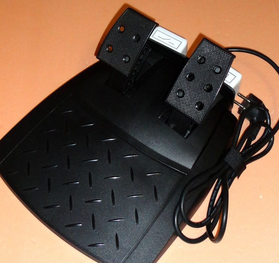
Due to the rubber pads (legs) and the fact that the heel of the foot is on the stand itself, the device does not move on the floor. In general, I was satisfied with the operational capabilities of the device. Further time will tell.
If something is missing in the description, I hope these nuances can be considered in the submitted photos. I apologize in advance for possible errors and typos.
If you need additional information, write to the post office, I will try to be sure to answer. Feedback, ideas, suggestions for improvements to the design and comments are very welcome.
The design turned out to be especially convenient when using drills installed in the drill stand. And when using a grinding machine mounted on a table. Conveniently control the blower to cool parts during soldering. Because both hands are free.
Due to the rubber pads (legs) and the fact that the heel of the foot is on the stand itself, the device does not move on the floor. In general, I was satisfied with the operational capabilities of the device. Further time will tell.
If something is missing in the description, I hope these nuances can be considered in the submitted photos. I apologize in advance for possible errors and typos.
If you need additional information, write to the post office, I will try to be sure to answer. Feedback, ideas, suggestions for improvements to the design and comments are very welcome.
November 2019