
When the top rotates, its kinetic energy gradually turns into heat, and soon it stops. Homemade, proposed by the author of Instructables under the nickname HowToEngineer, compensates for friction losses due to the supply of energy from the outside. The spinning top will spin continuously until it bothers the user himself and he turns off the device.
The principle of operation of the device is based on the interaction of magnets:
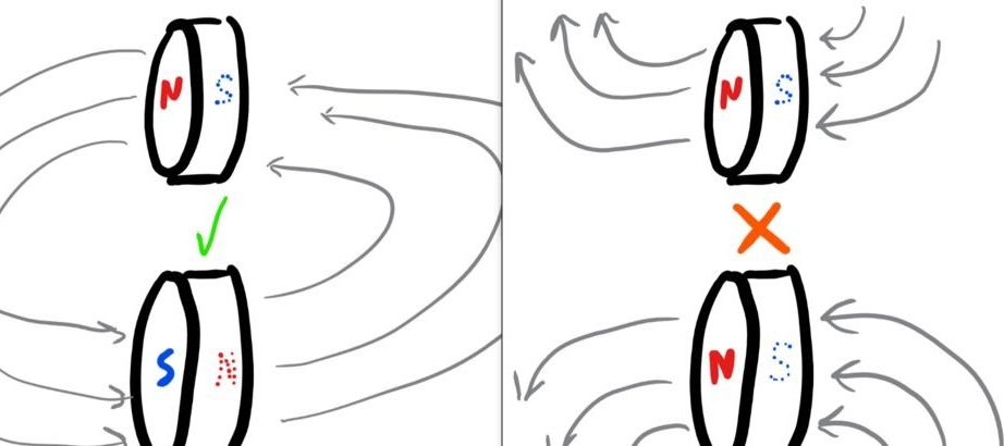
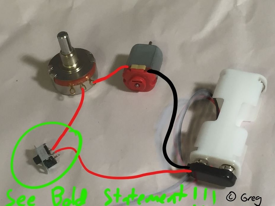
Outside - a magnet walled up in a top, inside - a magnet on a disk driven into rotation by an electric motor. Readers who suggested that several electromagnets are used in the design, alternately switched on by Arduinowill be disappointed. Or vice versa, they are delighted if they consider this to be over-engineering. The regulator of the rotational speed of the electric motor is a wire resistor.
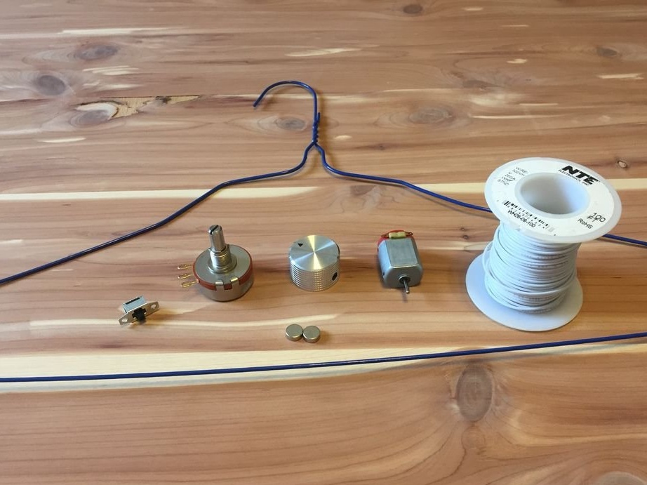
The following are some details of the device: a switch, a wire (required) variable resistor (ratings from 25 to 100 Ohms are suitable), an electric motor, a thin stranded wire, just below all this are two magnets, and around ... a hanger. Do not be surprised, it is very convenient for making the top of the top. If you bite a very small piece of steel wire from it, you can even use it further for its intended purpose.
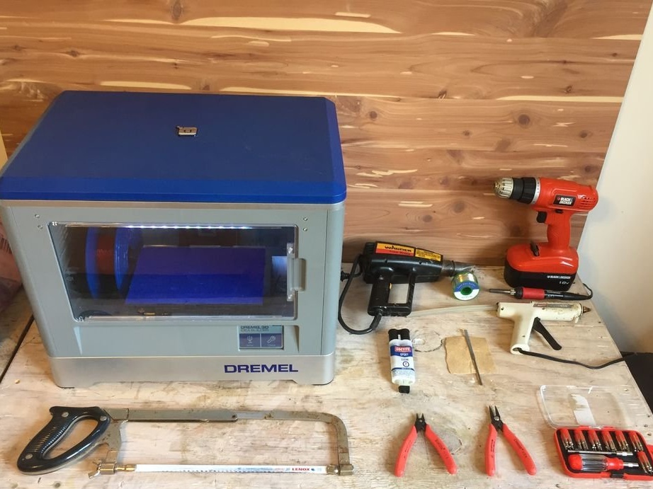
Of course, without tools you can’t. And if you have a 3D printer and a two-component epoxy resin, there is work for them.
Having developed all the 3D-printed parts, the wizard uploads two archives, one of which contains all files in FreeCAD formatsecond - all STL files. Then it collects the electrical part of the device:
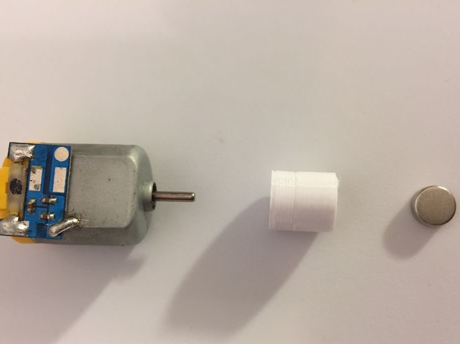
Attaches a magnet holder to the motor shaft, into which the magnet is mounted, and glues it with epoxy. While it dries, there should not be any objects nearby that can attract the magnet, thereby pulling it out of the adapter. Resin must not be allowed to enter the motor bearing - it will not be able to rotate. The polarity must be selected so that, when viewed from above, the engine rotates clockwise. If you are left-handed - counterclockwise.
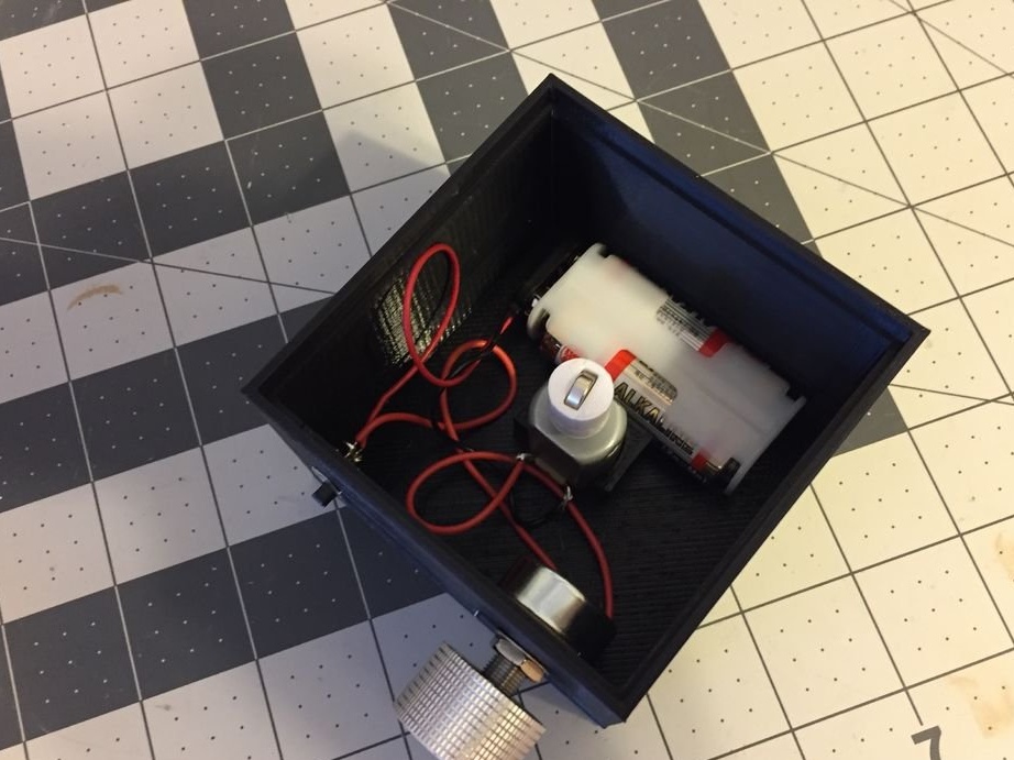
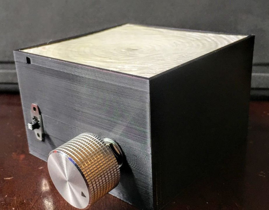
Installs everything in the case, the next photo shows how exactly the magnet is located in the adapter. It also becomes clear what to do with an engine mount and an adapter if there is no 3D printer. The handle for the variable resistor can be taken any suitable, ready-made or home-made.
The surface on which the top will rotate, immediately after 3D printing, is not suitable for this. The master polishes it, applies a layer of epoxy, hardens it, polishes it again and applies a second layer. After hardening, a smooth surface is obtained.
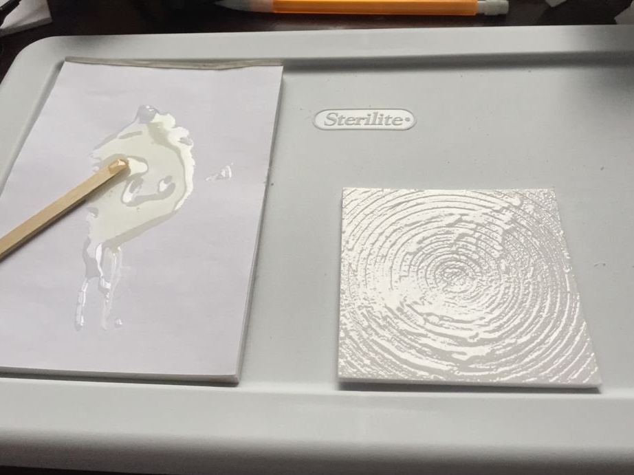
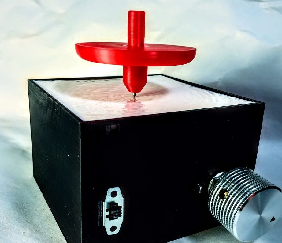
The finished part closes the case, and the device is ready:
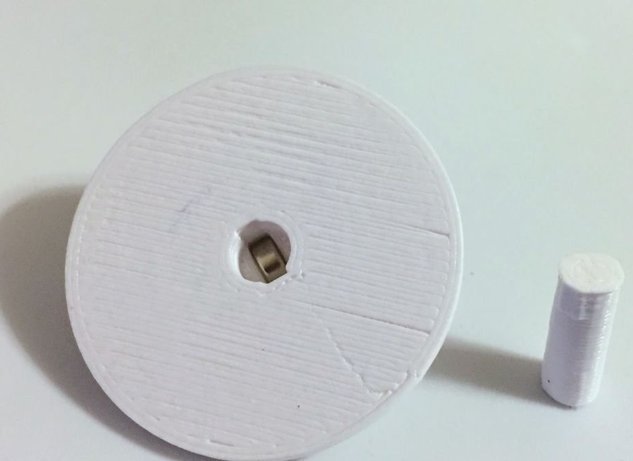
In 3D-printed tops (they can also be made in another way) installs magnets, covers them with cylinders and seals:
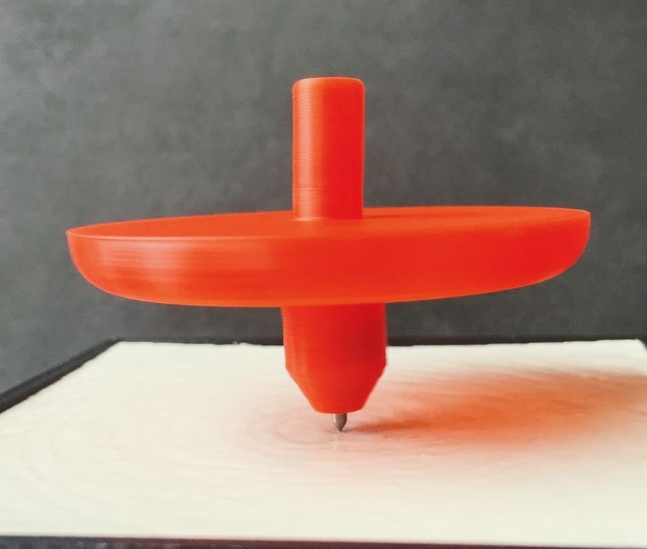
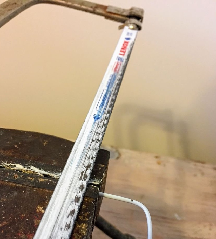
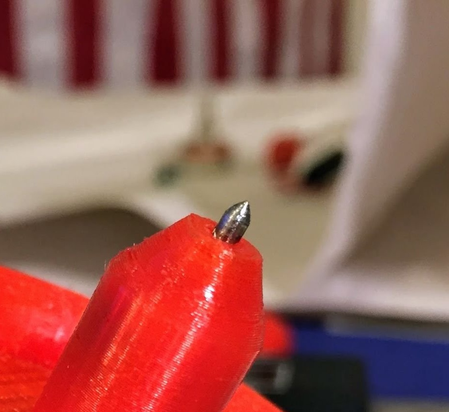
One of the two tops already has a plastic tip. You can use it right away, but it will quickly become dull - you have to grind it. For the second top, the master cuts off a small piece of steel wire from the hanger:
Sharpens it, drills a hole in the top, glues the resulting tip there:
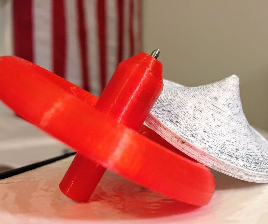
Both spinning tops are ready:
If the surface for the rotation of the top is not made by 3D printing, but in any other way, and it turns out to be immediately smooth, it must be sanded and coated with epoxy as described above anyway. Otherwise, it will quickly wear out from the impact of a metal tip. In any case, it is necessary to provide for the possibility of prying this part and removing it to access the battery compartment.
The master twists the variable resistor to a minimum, sets the top on the surface, untwists the top, turns on the power, gently rotates the variable resistor until the friction in the bearings is overcome - the engine starts to rotate. It increases the revolutions a little more, and then decreases until the engine speed coincides with the rotation speed of the top. That is synchronized with the engine, it will be noticeable by a sharp change in sound. Now you can increase the speed to the desired. The spinning top will rotate until the device is turned off, or until the batteries / accumulators are discharged, the brushes, engine bearings are worn, and the first top also has a tip. All faults are easy to fix, and everything will work again. You can also provide an input for a 5 V PSU and a pulse stabilizer to convert this voltage to 3.3 V, and also use a PWM controller instead of a variable wire resistor.