
The author of this material did not like the normal modes of operation of the flashlight BLF A6. Then he decided to flash the software part of the flashlight, setting its modes. As it turned out, this is not so simple, there is a minimum of information on the firmware and pinouts and he had to collect it bit by bit. And so that she would not get lost, he decided to help others and arrange everything in an article.
So, for work you will need the following:
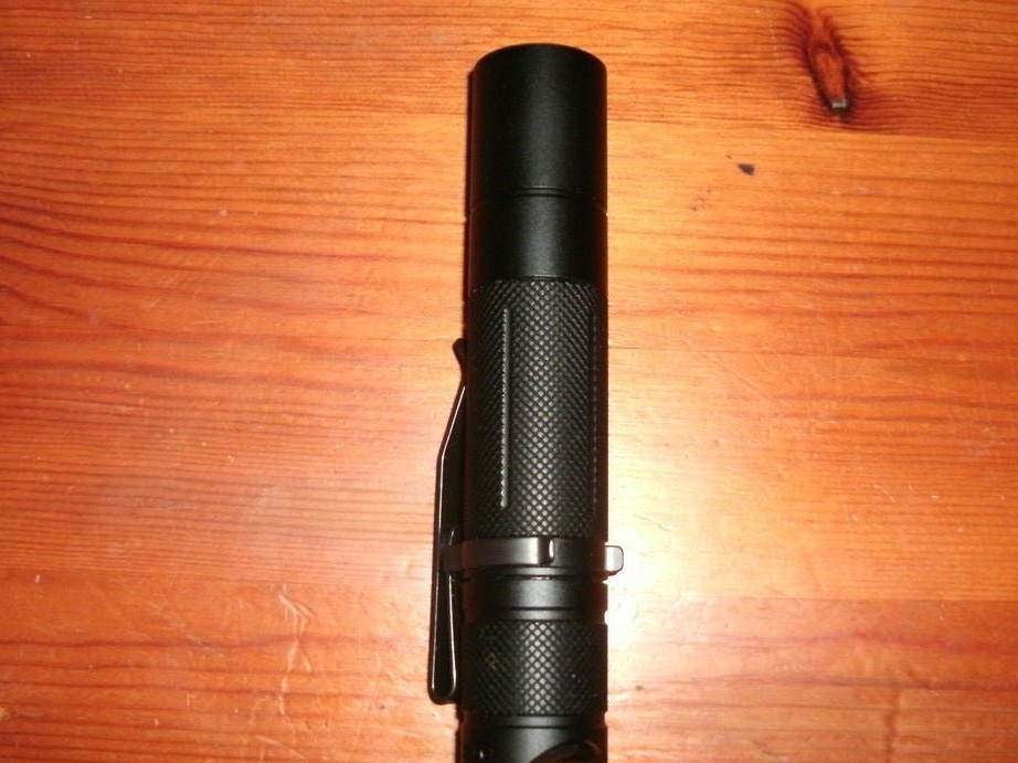
Flashlight BLF A6 (probably this will work with other flashlights based on ATtiny).
Tweezers / thin pliers / small scissors.
A computer for firmware, preferably with a Linux distribution.
USB ASP / Programmer Arduino / something that AVR programming can do (obviously, the USB ASP programmer is better, but the wizard used Arduino).
High-speed Rail-to-Rail amplifier [SOIC-8] (you can do without it, but it’s very inconvenient).
Development board and jumper wires for connection.
Firmware.
Firmware for BLF A6 (and many other flashlights) is available here. A discussion forum is available on this the link.
You can download the firmware by running the search "bzr branch lp: flashlight-firmware". Need flashlight-firmware / ToyKeeper / blf-a6 folder. It contains a compiled file. hex, ready for firmware (blf-a6.hex), and C code, which can also be changed (blf-a6.c). If you want to flash stock firmware, you can skip the next step and just use blf-a6.hex. Some other firmware in this repository will probably work as well.
Change firmware.
Attention symbols, so as not to distort the meaning, are given without translation.
Open blf-a6.c in your preferred text editor or IDE. The most interesting lines are the mode groups between lines 94 and 109. They look like this:
// Mode group 1
#define NUM_MODES1 7
// PWM levels for the big circuit (FET or Nx7135)
#define MODESNx1 0,0,0,7,56,137,255
// PWM levels for the small circuit (1x7135)
#define MODES1x1 3,20,110,255,255,255,0
// My sample: 6 = 0..6, 7 = 2..11, 8 = 8..21 (15..32)
// Krono sample: 6 = 5..21, 7 = 17..32, 8 = 33..96 (50..78)
// Manker2: 2 = 21, 3 = 39, 4 = 47, ... 6? = 68
// PWM speed for each mode
#define MODES_PWM1 PHASE, FAST, FAST, FAST, FAST, FAST, PHASE
// Mode group 2
#define NUM_MODES2 4
#define MODESNx2 0,0,90,255
#define MODES1x2 20,230,255,0
#define MODES_PWM2 FAST, FAST, FAST, PHASE
For each group, MODESN is the PWM value used for FET, and MODES1 is the PWM value used for 7135 in each mode. The number is in the range from 0 to 255 and corresponds to the brightness of the light. More information
here. (scroll down to "Mode control:") The master is not sure what the PWM speed is.If anyone knows, tell me in the comments. A field effect transistor can produce more light than 7135, but 7135 keeps the light level more or less the same throughout the life of the battery, while when using a field effect transistor, the light dims when the battery runs out.
Here we can adjust the PWM values to create modes to our liking. You can also change the number of modes, but the master did not do this because he needs four modes, and this is the number in the second group. He wanted a darker moonlight regime, and therefore set the first to 0/1. He also considers the turbo mode a little pointless, so I replaced it with 137/255, which is equivalent to the sixth mode in a group of seven modes.
When you have the code you need, you must compile it into a .hex file. At least you need gcc-avr and avr-libc. If you have problems, look at other dependencies in the readme file. The repository includes a build script, so all you have to do is run:
../../bin/build.sh 13 blf-a6
in the blf-a6 folder. ../../Bin/build.sh is the script. 13 indicates that it is for ATtiny13, and blf-a6 indicates that it is for BLF A6.
avr-gcc -Wall -g -Os -mmcu = attiny13 -c -std = gnu99 -fgnu89-inline -DATTINY = 13 -I .. -I ../ .. -I ../../ .. -fshort -enums -o blf-a6.o -c blf-a6.c
avr-gcc -Wall -g -Os -mmcu = attiny13 -fgnu89-inline -o blf-a6.elf blf-a6.o
avr-objcopy --set-section-flags = .eeprom = alloc, load --change-section-lma .eeprom = 0 --no-change-warnings -O ihex blf-a6.elf blf-a6.hex
Program: 1022 bytes (99.8% Full)
data: 13 bytes (20.3% Full)
The teams are already optimized in size, so if it is written that they are more than 100% full, try deleting
#define FULL_BIKING_STROBE
Line 125 spells small bicycle strobe light. If this is not enough, then something else will have to be cut.
When compilation is complete, the folder should contain a file named blf-a6.hex. This is compiled code, ready for firmware.
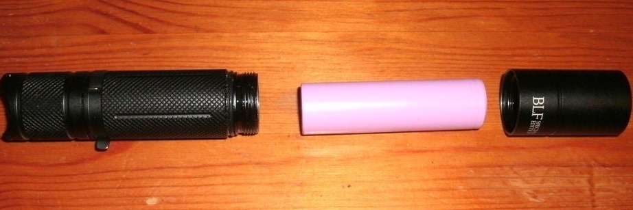
Dismantling the flashlight.
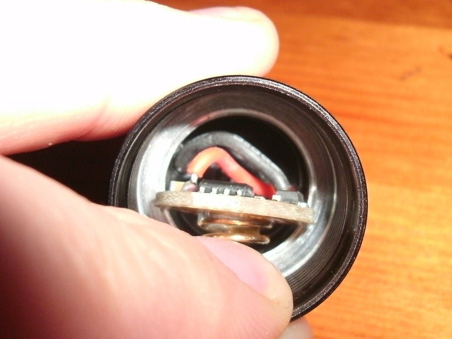
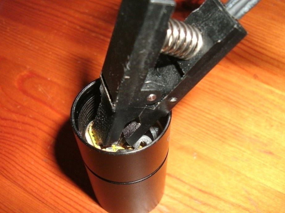
Unscrew the headlamp of the flashlight. There are two screw connections. The one that is closer to the flashlight body fixes the reflector and LED, and the one that is closer to the middle fixes the board. We need an average.
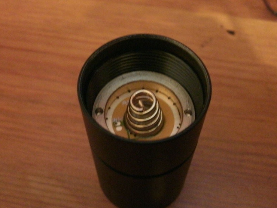
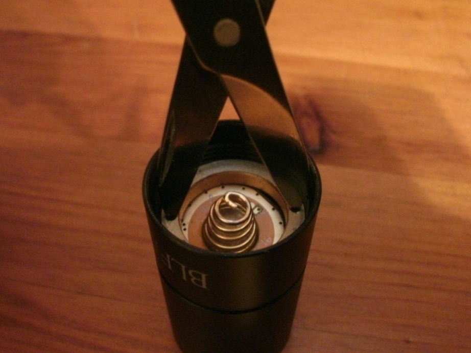
Inside you will see a snap ring with a spring and two holes along the edges. Insert tweezers / thin pliers / scissors into the holes and rotate them counterclockwise.
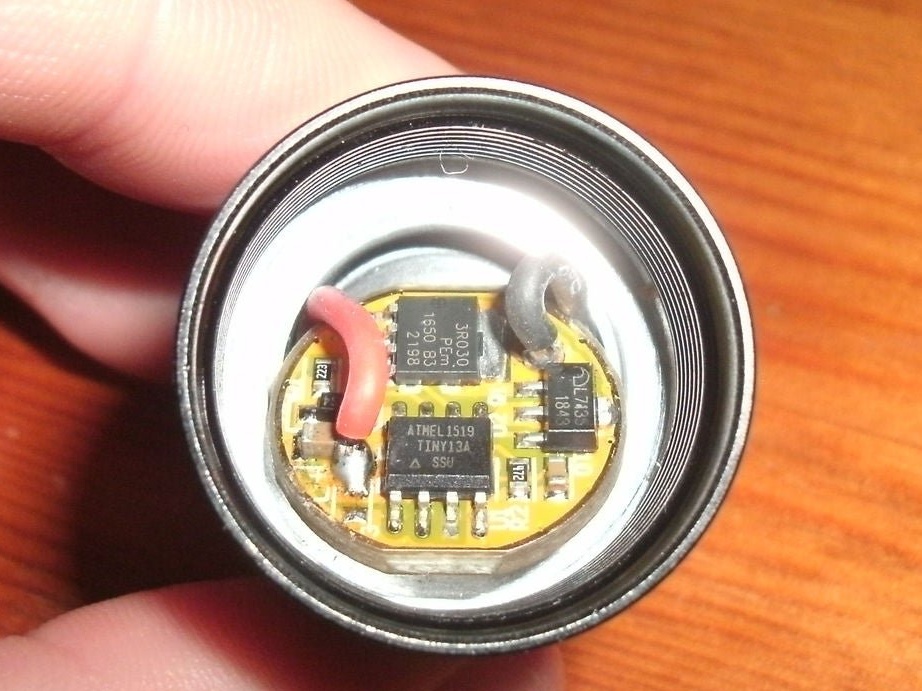
Once the ring is removed, you will have access to the board. It is still attached with two wires, so be careful. They are twisted together, so rotate the board until the wires are loose. Then turn the board over. It is necessary that the chip with the inscription "TINY13A" was more accessible.
If the wires are short and it doesn’t work out, then you need to remove the board.
Connection.
Now you need to prepare the board for firmware.
The wizard uses SOIC8 to connect the ATtiny13 chip and the programmer.

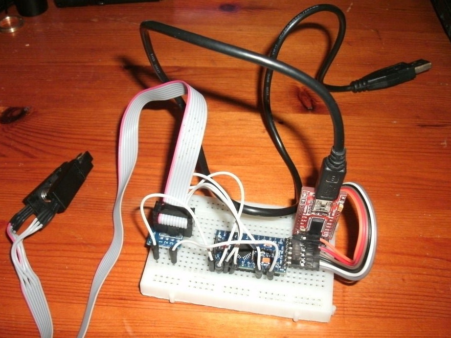
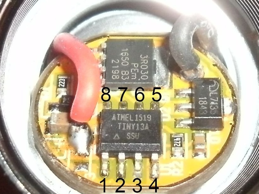
See the photo as the wizard makes the connection. Notice the red line in the second figure.
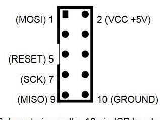
If you use the USB ASP V2.0 programmer, you need to connect it like this:
Pin 1 on ATtiny13 - Pin 5 on USB ASP (reset)
Pin 4 on ATtiny13 - Pin 10 on USB ASP (Ground)
Pin 5 on ATtiny13 - Pin 1 on USB ASP (MOSI)
Pin 6 on ATtiny13 - Pin 9 on USB ASP (MISO)
Pin 7 on ATtiny13 - Pin 7 on USB ASP (SCK)
Pin 8 on ATtiny13 - Pin 2 on USB ASP (VCC)
If you use Arduino, like the wizard, then follow these steps:
Open the Arduino IDE and make sure your Arduino is connected to the computer. Find the ISP sketch in File> Examples> 11.ArduinoISP> ArduinoISP and upload it to Arduino. Then connect the ATtiny13 to it as follows:
Pin 1 on ATtiny13 - Pin 10 on Arduino (reset)
Pin 4 on ATtiny13 - GND on Arduino (Ground)
Pin 5 on ATtiny13 - Pin 11 on Arduino (MOSI)
Pin 6 on ATtiny13 - Pin 12 on Arduino (MISO)
Pin 7 on ATtiny13 - Pin 13 on Arduino (SCK)
Pin 8 on ATtiny13 - VCC / 5V or 3.3V on Arduino (5V preferred)
Firmware.
Step 5: flash it
For firmware, you must install AVRDUDE. To check if this works with Arduino, the wizard writes a command:
avrdude -v -p attiny13 -c stk500v1 -P / dev / ttyUSB0 -b 19200 -n
If this works, go to the empty folder and register:
avrdude -v -p attiny13 -c stk500v1 -P / dev / ttyUSB0 -b 19200 -u -Uflash: r: flash-dump.hex: i -Ueeprom: r: eeprom-dump.hex: i -Ulfuse: r: lfuse -dump.hex: i -Uhfuse: r: hfuse-dump.hex: i
Make a backup copy of existing firmware. To flash, from the folder with the modified blf-a6.hex it starts:
avrdude -v -p attiny13 -c stk500v1 -P / dev / ttyUSB0 -b 19200 -u -Uflash: w: blf-a6.hex -Ulfuse: w: 0x75: m -Uhfuse: w: 0xFF: m
You need to specify stk500v1 as a programmer, and specify the port and data transfer speed. If you are using Arduino and are in doubt, try disconnecting ATtiny13 from Arduino and upload the sketch to the Arduino IDE using these settings. This will not work, but you will find out which command is used in the console window. Next, you can copy the attributes to the AVRDUDE command.
If you are using a USB ASP programmer, run:
avrdude -v -p attiny13 -c usbasp -n
To see if this works:
avrdude -v -p attiny13 -c usbasp -u -Uflash: r: flash-dump.hex: i -Ueeprom: r: eeprom-dump.hex: i -Ulfuse: r: lfuse-dump.hex: i -Uhfuse: r: hfuse-dump.hex: i
Make a backup:
avrdude -v -p attiny13 -c usbasp -u -Uflash: w: blf-a6.hex -Ulfuse: w: 0x75: m -Uhfuse: w: 0xFF: m
To flash:
-Uflash: w: blf-a6.hex. Replace blf-a6.hex with your file name if it is different.
-Ulfuse: w: 0x75: m and -Uhfuse: w: 0xFF: m
If an error occurs, this means that the image file is too large to fit on the chip, and you will have to delete part of the code. If everything is normal, some progress indicators should be displayed, and then the words "avrdude done. Thank you."
After you have flashed the chip, assemble a flashlight and see if it works.