
The power management device proposed by Instructables under the nickname Yannick99 is an electronic analogue of a self-locking relay. When a button is pressed, a MOS transistor opens in it, connecting the power source to the voltage regulator. The load powered by the output of the stabilizer is turned on, the microcontroller included in its composition or another logic circuit starts to work and feeds a logical unit to one of its outputs. It goes to the input of the power management device, after which the button can be released - the transistor will remain open. When a logical zero arrives at the power control device from the load side, the MOS transistor closes, removing the supply voltage from the stabilizer, and therefore from the load. The device is returned to its original state and is ready for the next turn on by the button.
Work on homemade the master begins by drawing up her diagram:
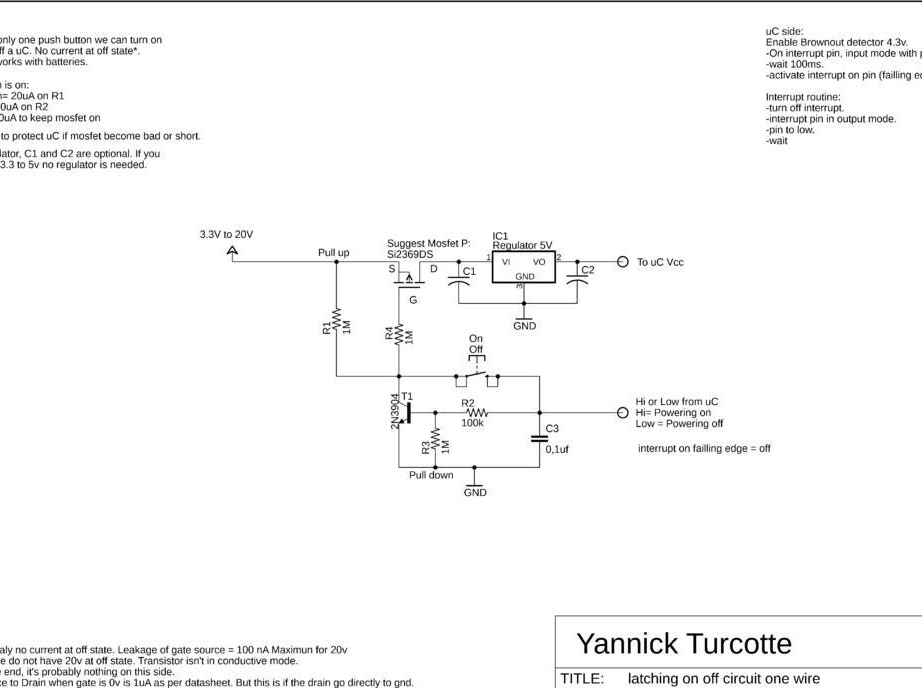
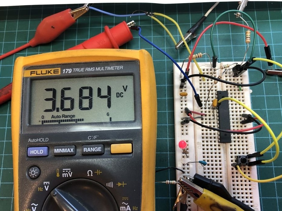
The wizard checks the circuit by assembling it on a breadboard of the breaeboard type (see KDPV). The used MOS transistor for a datasheet is designed for voltages up to 20 V. In the experiments of the master, it worked normally at voltages up to 30 V (but here it should be borne in mind that there is a linear stabilizer after the transistor, and a large voltage drop for it is a heavy mode). At 35 V, the transistor failed and required replacement, having remained open forever, regardless of the voltage at the gate.
Then the master observes with the help of an oscilloscope the transient processes that occur when turning on and off. Moreover, he connects the oscilloscope to the control input to make sure that it will never receive an increased voltage from the microcontroller or logic circuit. It turns out that it does not exceed 3.7 V even when powered by a voltage control device of 20 V.
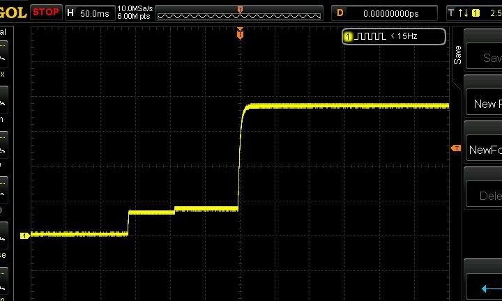

Now, making sure that the microcontroller is not in danger, the wizard writes a test firmware for it and uploads its source code in C here. After compilation, the program will run on an ATmega328 microcontroller. It can also be processed for other microcontrollers of the AVR family, if you have a microcontroller of a different architecture, you will have to write your own firmware.By connecting the microcontroller, the master makes sure that everything works:
Possible improvements to the control device:
1. Replace the linear stabilizer with a pulse one.
2. Apply a MOSFET withstand more voltage.
3. Install a button with normally closed contacts (NC) between the output of the stabilizer and the control input of the control device, then no signal from the load side will be needed. Like a self-locking relay or RS-trigger, the power can be turned on and off with buttons. Both buttons (on and off) can be of type SB-7. These are inexpensive and large buttons with fairly "delicate" terminals, but if you tighten them carefully, without fanaticism, they work quite reliably and for a long time.
4. Transfer the circuit from the breadboard to a perfboard or printed circuit board, or assemble the circuit by surface mounting, place it in a common housing with a load.
5. By adding additional cascades, remodel the device into a touch switch with latching.