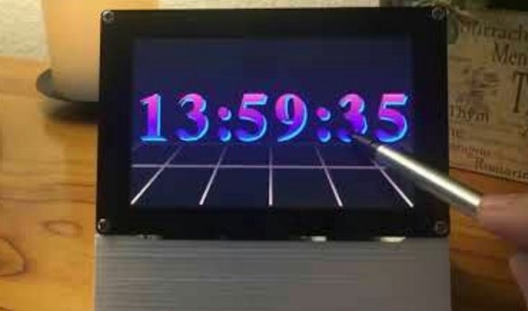
The author of Instructables under the nickname marciot back in the eighties saw on a computer, which was then called not short - Mac, as now, but completely - Macintosh, a clock program in the style of Salvador Dali's work, where the numbers do not change sharply, but gradually change shape. Today, getting a similar effect is not a problem - there is a very old open-source program xdaliclock, originally written for Xerox Alto workstations, and then ported to Unix-like operating systems. But it works on a PC, and the master wanted it to be a separate desktop clock that will never be closed by other running programs.
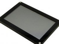
The wizard decides to apply in homemade display on FTDI's FT810 chip, better known as a manufacturer of USB-COM interface converters. In addition to the display driver, this chip has built-in video memory, a GPU, a music synthesizer, a sensor data reader with multi-touch function, and even a JPEG hardware decoder. This allows you to significantly unload such a low-power platform as Arduinoby shifting a number of functions to the peripherals built into the display. Well, modules consisting of a display, a sensor and this chip are produced by Haoyu Electronics.
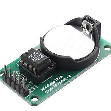
The following is a fairly common real-time clock (RTC) module on the DS1302 chip:
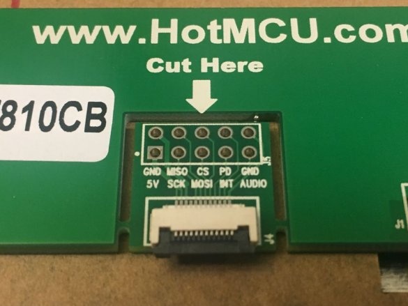
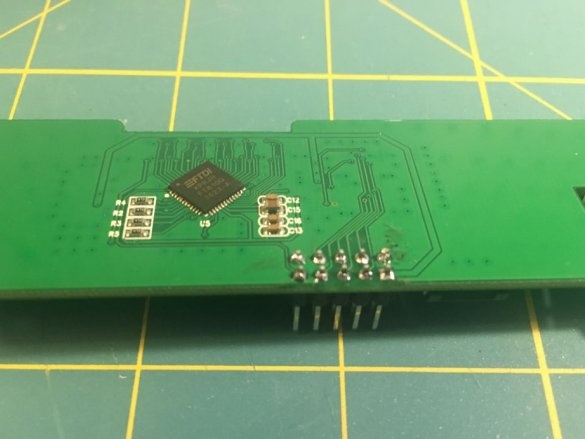
Having received the display, the master disconnects the cable from the riser board, solders the double-row comb (two single-row ones are also suitable), seals the rations with insulating tape, puts the board back in place and reconnects the cable. Instead of a comb, you can solder a cable or individual wires, but in this case the display will be non-removable.
The wizard prints the stand (3D models and source codes are here) Of course, the stand (or case) can be made in another way.
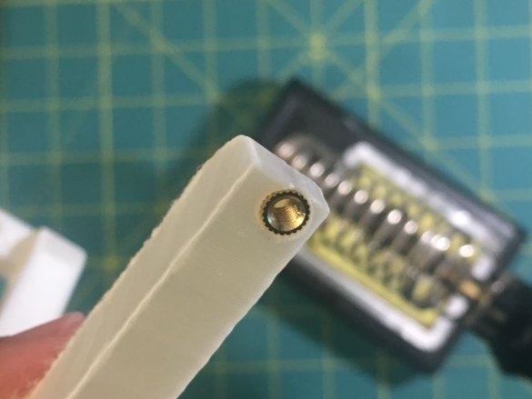
It melts with a soldering iron of a rack, the outer surface of which is ribbed to avoid turning in plastic, and the inner one is threaded.

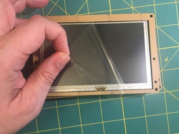
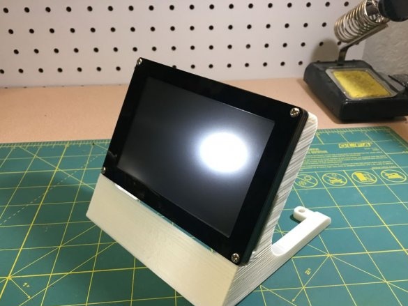
Having removed the protective film from the display, it installs it on the stand:
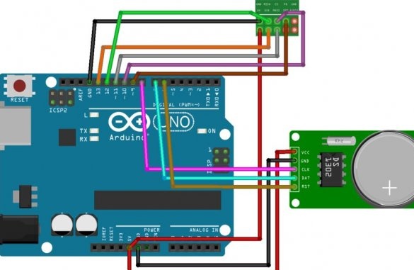
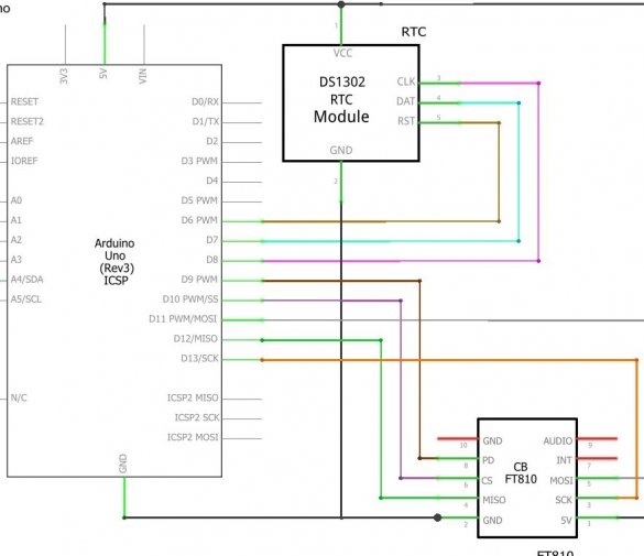
In the program, Fritzing draws up a diagram and displays it in two ways - Fritzing and usual, so that the supporters of either one would like it:
Collects all electronics, after which it is taken for software. Arduino is a low-power platform, so porting xdaliclock to it is not possible.But you can take images from there, and write all the code from scratch. These images, like the xdaliclock program itself, are available under the X11 license, which is less strict than the GPL. Therefore, the master licenses a set of new code and available images under the GPL (to do the opposite - to license under X11 what is made of something available under the GPL is impossible) and uploads here.
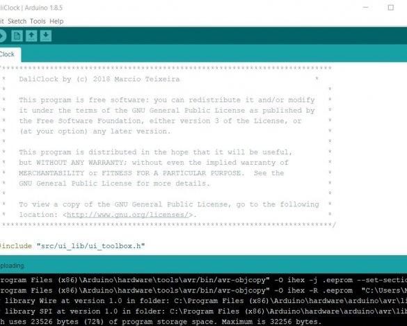
The wizard compiles the existing INO file in the archive and uploads it to Arduino, but you can correct the colors before compilation. If desired, the watch can be made generally monochrome, it will be like on Alto or the early Macintosh.
clock.fill_gradient (0xFF0000, 0x0000FF);
grid.fill_gradient (0x000000, 0xFF8800);
shine.fill_gradient (0x7F7F7F);
Also, in the DaliClock / src / ui_lib / ui_config.h file, you can adjust the pin set to which the display module is connected, and in the DaliClock / src / ds1302.cpp file, you can adjust the pin set to which the real-time clock module is connected.
Clock setting:
1. Click on the discharge, its value will begin to increase until you release it.
2. Click on the bottom of the screen - the watch will switch to calendar mode.
3. Set up the calendar in the same way.
4. After stopping tapping the screen, five seconds will automatically return to clock mode.
Both videos in the article are under CC-BY: the first - it is not indicated which version, the second - 3.0.

