» Electronics » Power supplies »Adjustable power supply - very simple, even a schoolboy can do. In detail

An adjustable power supply is very simple, even a schoolboy can do. In detail

And again, I am glad to welcome You Dear master friends!


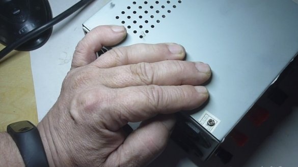
Today, I want to talk with you about old and seemingly worthless dusting in the corner of an apartment or the garagecompleting your old computer. In particular, about an old computer power supply unit, not working people in your eyes, but still issuing its own 12V DC voltage.

The computer power supply, I can say with great confidence, is the perfect device for any master. From a computer power supply, you can make a good regulated source of constant voltage.

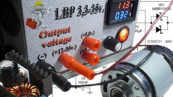
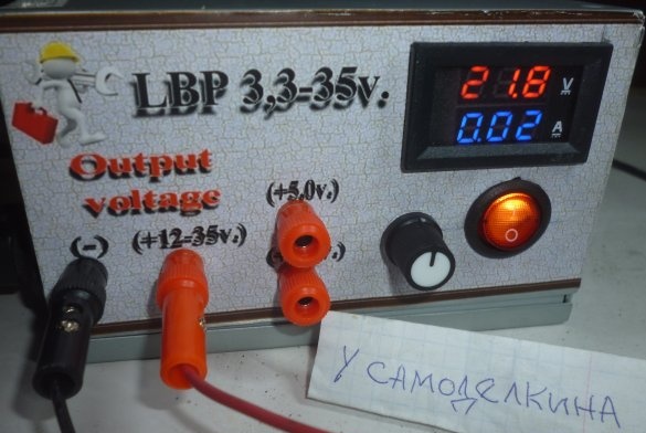
Today, the price of a laboratory power supply reaches ten thousand rubles. But, there is a good option, just remake the computer power supply into an adjustable laboratory power supply. Of course, it will not be so accurate, but it is quite suitable for the work of a home master. And it will cost YOU about 350-400 rubles. Having spent one and a half to two hours of your time, you will get a power supply for: 3.3 V, 5 V and an adjustable voltage of 12-35 Volts, a pretty decent power.

Adjustable power supplies are good in that they enable the master, the master, and simply the consumer, to regulate the output voltage. Such power supplies can be used for various purposes, for example: for checking incandescent lamps, LEDs, charging batteries and for powering various electrical and electronic devices in your workshop.

And to summarize, a power supply with voltage regulation at this modern stage is an absolutely necessary thing for any real man, with his hands growing not from n @ py. This simple device, due to its technical properties, can easily convert the voltage and current available in your electrical network to a level that is suitable for the consumption of a particular electronic device.

I want to offer a budget option for an adjustable power supply, as noted above, for accessories, it will cost you 350-400 rubles, agree 400 rubles is much less than 10 thousand.

This power supply, I’m sure, can be done by any novice master who has at least the idea that the current runs through the wires. In the article I will describe in detail the manufacturing process of the power supply, and if you are interested in this device, I will conduct detailed installation of all the wires and systems of this device in the video clip of the instruction.

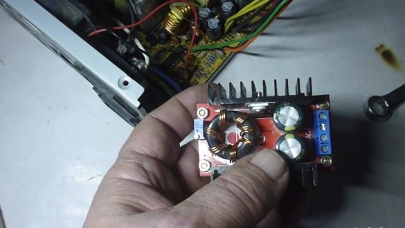
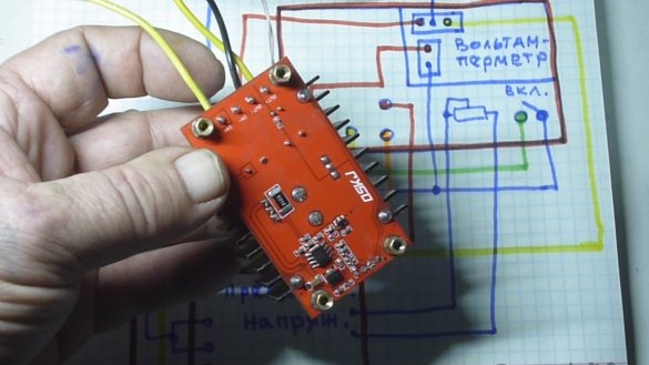
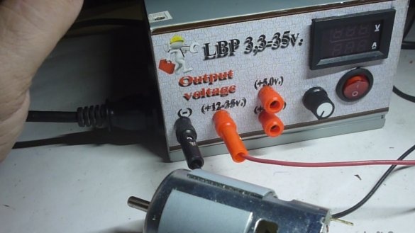
The idea of ​​an adjustable power supply is very simple. Now in Chinese online stores appeared DC / DC converters. In our case, the boost converter with the declared power of 150 watts is taken as the basis. (Our Chinese friends, of course, as always overestimate these parameters, but there are probably 100 watts.), With a fixed power supply from 10 to 30V and an adjustable output voltage from 12 to 35V. Links to Aliexpress where you can purchase this converter and accessories for our power supply are available in the video clip.

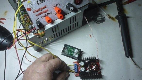
Having powered this converter from our computer power supply unit with 12 volts of constant voltage, at the output we get an adjustable voltage of 12-35V. Also in the computer power supply there are fixed voltages 3.3V and 5V. We will also remove them on our device.

It has already become a tradition in our articles to talk a little about safety precautions. My advice to you: never check the availability of electricity in your tongue and you will have a wonderful Hollywood smile and a good, easily digestible speech. Do not stick your arms and legs in those places where the dog does not stick its tail, and you will still dance the gypsy and play the piano.
For safety, basically everything.

Getting to the production homemade.

In the beginning, for those who like to watch more than read, video clip instructions on how to make an adjustable power supply from an old computer unit:

Video clip of manufacturing a power supply:


Video clip connecting a multimeter DSN-VC288

100V and 10A (a detailed description of the ladies in a separate article):


Tools that are useful in the manufacture of our device:


1. Soldering iron.
2. Screwdrivers.
3. Drilling machine or drill.
4. Drills.
5. File or file.
5. Emery cloth.
6. Stationery knife.
7. Wrenches.
8. Measuring tool, at least a ruler.
9. Descriptive tool, pencil.
10. Kerner.
11. Pliers or pliers.
12. Cutting machine (grinder) with a cutting wheel and grinding.

Consumables Required:


1. Solder.
2. Soldering acid.
3. Bolts and nuts.
4. Installation wires.
5. Step-up voltage converter.
6. Voltammeter 100V, 10A.
7. Plugs, connectors and other trifles.
8. The switch.
9. Variable resistor.
10. Heat shrink tubes.

The procedure for manufacturing an adjustable power supply:


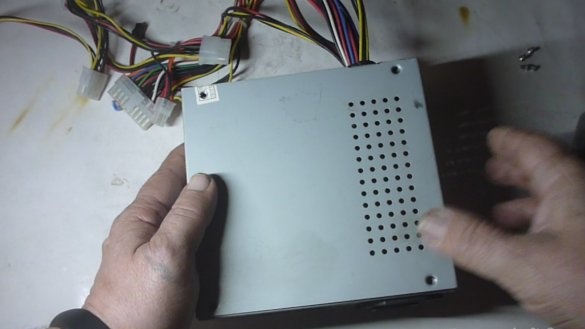
1. Find an old, working computer power supply.
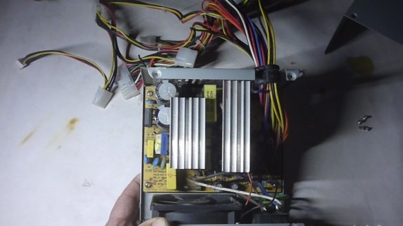
2. Open thoroughly but gently clean from accumulated dust and dirt.
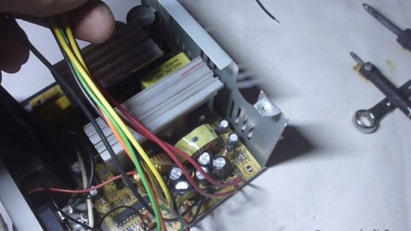
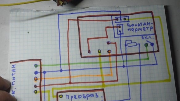
3. To remove excess wires from the bundle, leave black minus power, yellow 12V plus, orange 3.3V plus, red 5V plus, and green to turn on the power supply.
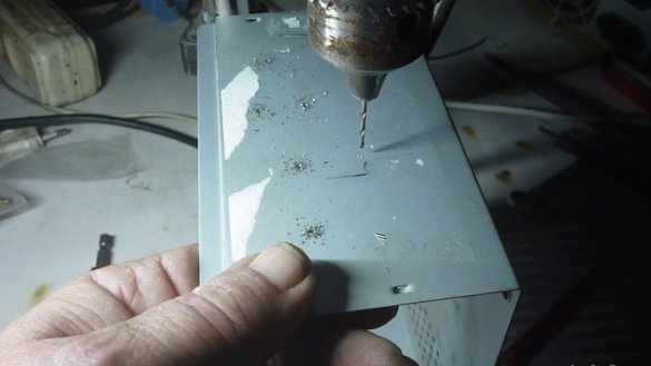
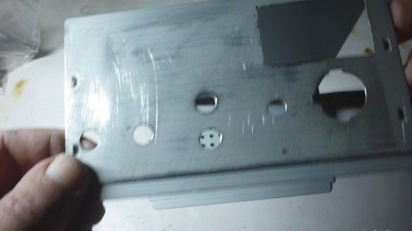
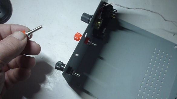
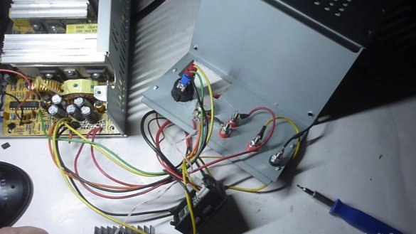
4. On the front panel of the power supply, drill and drill holes for mounting control devices, control knobs and voltage relieving connectors from our device.
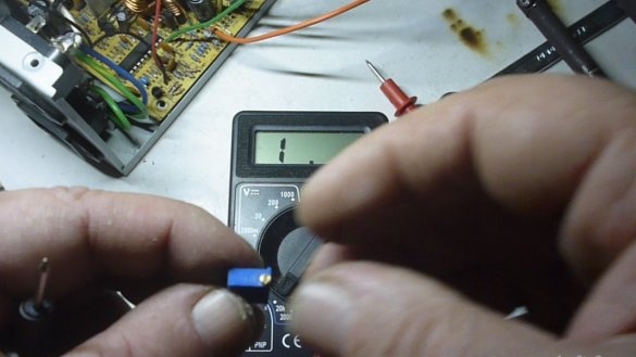
5. Solder the tuning resistor from the step-up voltage converter, solder a 10 kΩ variable resistor in its place.
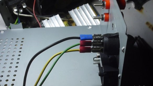
6. Solder the wires of the power supply unit, it is shown in detail in the video clip, do not panic, everything is very simple, the main problem is not to burn your fingers with a soldering iron :-).
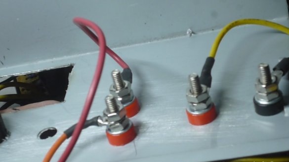
7. On the front panel, place and secure the multimeter, control knob, switch and voltage relieving connectors.
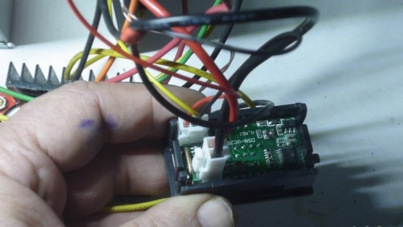
8. Connect the prepared wires to the multimeter, control knob, switch and relays.
9. Place and raise the step-up voltage converter connected to the power supply unit and fix it in our power supply unit. The full-time position is shown in the video.
10. Assemble the case of the resulting power supply.
11. Connect the power supply to the 220V network.
12. Click on the switch to turn on the device.
13. A voltage should be displayed on the multimeter.
14. Set up and test the regulated power supply under load.

Technical analysis:


Pros:

1. budget costs for component structures.
2.sufficient compactness.
3. Easy to manufacture.
4. Easy operation.

Minuses:

1. Insufficient accuracy of the device, from 10 mA.
2. The voltage is adjustable from 12V. 3.3 and 5V fixed voltage. But we are working on it.


That's all for today! Good luck to you!
5.2
5.8
6.2

Add a comment

    • smilesmilesxaxaokdontknowyahoonea
      bossscratchfoolyesyes-yesaggressivesecret
      sorrydancedance2dance3pardonhelpdrinks
      stopfriendsgoodgoodgoodwhistleswoontongue
      smokeclappingcraydeclarederisivedon-t_mentiondownload
      heatirefullaugh1mdameetingmoskingnegative
      not_ipopcornpunishreadscarescaressearch
      tauntthank_youthisto_clueumnikacuteagree
      badbeeeblack_eyeblum3blushboastboredom
      censoredpleasantrysecret2threatenvictoryyusun_bespectacled
      shokrespektlolprevedwelcomekrutoyya_za
      ya_dobryihelperne_huliganne_othodifludbanclose
124 commentary
Guest Alex
I am waiting for the third time a question about a washing machine ...
Guest Alex, "... the third time he threw a net." ;)
What are you waiting for?
Guest Alex
waiting for the third time
astemir
Good afternoon. Is it possible to unwind the enameled wire from the engine from the washing machine and wind it onto the transformer on the secondary to make the charger? thank you
Dzugkoyev astemir,
You need to look at the winding, if it is saturated with varnish, then 100% is not, if not saturated, then 50%. Insulation damage is difficult to avoid, but if there is no other way ... meeting
Dzugkoyev astemir, possible, but not necessary. If the issue with the diameter is easily solved and it will be possible to find out the differences in currents, then what about the issue of insulation, is it damaged? If you are sure of this, then go for it.
Dzugkoyev astemir
good afternoon. is it possible to remove the enamel wire from the engine from the washing machine and wind this wire onto a transformer on the secondary to make the device charge? thank you in advance
Quote: Korolev
ino53, Met in old Sparkman-ah + 3.3V received from + 5V, if the memory does not change!

Yes, of course, and sometimes -5V from -12 was obtained simply by installing 7905. The PWM is regulated based on 5 and 12 V, the rest are monitored only for the purpose of leaving the permissible range, because they (voltages) all go from one winding, are interconnected friends
ino53,
but on the channels 3.3, -5, -12 V - yes there, out of range, you bam! emergency turn-off
Met in old Sparkman-ah + 3.3V received from + 5V, if the memory serves!
Korolev,
Not certainly in that way. Voltages 12 and 5V (after the dividers, ec-no) are mixed at the input of the op-amp and the MS does not allow them to change the top of the range by changing the duty cycle. It turns out the following picture: 5 V channel on Х.Х. it produces 5.25 V, the upper limit, and on the loaded channel 12 V it is actually 11.2 V (conditionally), and the controller considers this normal. On these channels (5 and 12V), the OOS fulfills the PWM-ohm voltage change, but on the channels 3.3, -5, -12 V - yes there, out of range, bang on you! emergency turn-off. So these circuits are disconnected, but there are especially foul microcircuits, for example. 6105, her supervisor is built-in, do not disconnect, so that instead of 12 to get 14.4 V, you have to simulate the missing voltages of 5 V, 3.3 V (+ -5%), since the negative control can be put on the ground.

Igor Leonov

I heard a jingle ... mda
Igor Leonov,
until you load the 5-volt channel, because the voltage is stabilized from it.
I will not say categorically, but in many schemes of computer PSUs, the PWM controller supplies voltage from the divider between + 12V and + 5V! Accordingly, the skew on any channel is perceived as an emergency, and the PSU goes into defense! yes
Igor Leonov
Owners of homemade PSUs based on a computer ATX power supply, do you take into account that the output power of the 12v channel depends on the load of the 5v channel? You will not get a normal current until you load the 5-volt channel, because the voltage is stabilized from it.
Guest Vladimir
For about forty years I have been using this connection of electrolytic capacitors, 40x450 volts as starting for three phase motors, they have been working for years. I do not connect diodes. Capacitors soldered from Soviet TV.
Guest Dmitry
Not for the sake of advertising. I made a power supply on its base. A lot of the necessary information.
R555
......
They have an interesting mount - a hole is made in the board (pah, a hole! Hangovers swear ... derisive ) on a smaller diameter and plant the poor on an epoxy. It was, under the Union, the 7th or 9th acceptance of the PZ (aviation, space).
And this is the tantalum capacitor you wrote about.

From my collection.
K52-2 150 uF, 70 V !!!
Released in 1974!
I checked it works.
As a keepsake, I’ll say that in such cases there is not only tantalum, but also silver and even sulfuric acid.
They were also produced under the brand ETO1, ETO2. (Mushrooms).
ino53 Of course, I would have handed over these capacitors and KM too, bought a new car.
But, while I wait. boss
... ....

......
And then it says: ... W ...
And further
... rub...
Did I promise to find a non-polar electrolyte?

Found. I have them in cash from matchboxes in bulk.
And I understood, just saying exactly, the operating voltage of 15 Volts, 2 exactly 30 turned on.
K53-7 year of manufacture 1984.
A little late for evening srach pleasantry
......
I'm a phase shifter ( xaxa ) somehow represented differently ..

(Well, this refers to the shortcomings of education.) But if the losses on it are unacceptably large, do not call it ...
As for non-polar capacitors.

I rummaged in the bins, the left - non-polar K50-6-10.0 * 25 V, the right - polar K50-35-10.0 * 63V, how much less. When I was engaged in amplifiers for cocks, non-polar people come across in some models. And in the amplifiers "Krok-500", "-800" in one place where the polarity was not determined by the circuitry, there were polar capacitors, and if the polarity floated in the opposite direction during temperature drift, an unpleasant noise appeared. In order not to cut the bottom, put these jars of 5 in parallel.
Chet brought me in the wrong direction ... ne_othodi
2 R555
K53-1, K53-4 with tantalum, for a long time everyone left for precious metals, K53-14 remained. Non-polar did not come across, although before the collapse of the Union he worked in the military-industrial complex.
Ivan_Pokhmelev

I’m talking about such capacitors with a rhombus on the case, they were released for war. I have never seen them in a civilian.
So, the non-polar one has 2 glass insulators on the terminals, I will find, I will show.
There are definitely no resistors inside. Why are they? Yes, and diodes are unlikely. Most likely, two oncoming capacitors.
K53 did not meet non-polar. Caught K50-6 or K50-16. Something like 50 microfarads at 16 V, but in volume - like 200 microfarads.
I have a non-polar electrolyte capacitor lying somewhere. Have they put equalizing resistors inside, or maybe diodes? xaxa I’m writing a Kondyuk of the K53 series.
And that the "ballast" capacitor does not shift the phase? In addition, the rectifier standing after your phase shifter is deeply purple, what is the phase shift. The meaning of capacitors in your circuit is in decoupling for alternating current, and not in phase shift.
I wrote a little earlier that in the place of the author of this circuit, I would use non-polar electrolytes. Well, since this is one of the simplest phase shifters, just instead of the resistor, the load acts.
The capacitor looks into the circuit and decides whether to shift its phase or not? And what principles ensure reliable operation of a polar capacitor in the absence of a polarizing voltage?
This is just extremely important for us. I will not dispute your measurements, they were correct, with the exception of one nuance. What you measured is a ballast capacitor. That on that circuit is an elementary phase shifter of about 90 degrees. And this is a completely different principle of work.
Author
Quote: Guest Alexander
where could I buy?

ino53
And this is a misunderstanding with capacitors in front of the second bridge
A misunderstanding, but how much pleasant communication! goodgood
Mean winding with a midpoint? Undoubtedly! And this is a misunderstanding with capacitors in front of the second bridge (not mine! agree ) floated somewhere earlier.
Guest Alexander
Quote: brnjh1
400 watt boost module

Where to buy?
ino53
I thought so too, but 42 V drops out of 220 V - almost 20%, wow!
After analyzing the work you have done, I concluded for myself: for a good power supply it will be easier and more correct to rewind the secondary! yes
Boyarin
I’ll stuff it into the phone
Today Garik Sukachev sings all day that his grandmother smokes a pipe! smile
Author
Quote: Boyarin
I take a shag

I tried the shag when I was young, now not, one cigarette roll on the floor of a pack of cigarettes will pull: - (((
Even now, I’m taking the shag for fishing. I’ll smuggle it into one’s pipe. About 50-70 rubles. For a pack.
If we take capacitors of 1 nF, then in general everything will fall on them. ;)
Capacities are selected based on the load parameters. If you just need to untie the break, then you need large tanks. And sometimes, when using capacitors as ballast resistance, the capacitance is calculated based on the reactance of the load, while a large voltage drops on the ballast.
Infection, one drawing does not accept, requires text. smile
Author
Quote: Korolev
I did not grow a samosad

And there was shag, I don’t remember exactly, around 10 kopecks per pack, goat legs were twisted. There was a single infection, it looked like sawdust in form. :-)))
You are like me.
It’s necessary to sleep sometimes and make home-made rivets.
Yesterday I finished mine, showed it to a friend of the radio amateur, he said BUY.
And the price, in principle, announced normal.
But I refused. He said that the author’s version is not for sale. boss
Dude does not know yet about the site "Imdmyself.com". xaxa
Ok guys, tomorrow (more precisely, today) in the morning, I want to sleep.
.....
I thought so too, but 42 V drops out of 220 V - almost 20%, wow! And nonlinear things, diodes with their parts, units of volts, are a trifle, of course. And the phase shift between voltage and current is not excluded, although this is for us ...
Ivan_Pokhmelev
This resistance, in turn, is much less than the load resistance.
And let's ask dear ino53 sketch out the sketch of his last experiment!
It is unlikely that the difference from the sine will be significant. Roughly approximately equivalent is a circuit of two counter-parallel connected diodes, in series with which a resistor is connected with a resistance equal to the reactance of the capacitor at a frequency of 50 Hz. This resistance, in turn, is much less than the load resistance.
On diodes, no more than 1 ... 1.5 V drops even at the highest currents, which is a trifle compared to the mains voltage, which you can not pay attention to.
ino53
Why not a sine, straight from the outlet
Dear colleague, I will not undertake to assert categorically, but it seems to me that in this particular circuit, the shape of the current in a particular section of the closed circuit will be significantly different from the sinusoidal, given the reactive nature of the load and the presence of diodes, although I may be wrong ...
... ... scratch ...
Why not a sine, right from the outlet. And yes, there is more confidence in the switchman, but (see the 2nd photo) there is little for a voltmeter, the nonlinear part of the scale, but for the ammeter a lot, it goes through the roof, poor.
Connect to a common wire
ino53
Your calculation is more accurate than my intuitive estimates
Thank you, of course, with a kind word, unfortunately the calculation is not mine ... I just always knew that the capacitor does not conduct any current, there is an insulator between the plates. A capacitor accumulates energy during a charge and gives it up during a discharge, something like that ... By the way, I would not really trust the readings of devices in your specific circuit, because it is not clear what values ​​are measured on a non-sinusoidal form of the measurand ... scratch
2 Korolev
Yes, dear colleague (without irony and sarcasm), your calculation is more accurate than my intuitive estimates. In the photo - C = 150.0 * 400 V, 2 pcs., D112-25-8 2 pcs. and C5-16-2-1%, in the amount of 0.1 Ohms as a shunt. At the top - a voltmeter shows the voltage drop across the load, i.e. capacitors, about 140 V, cartoon - voltage per 0.1 Ohm, i.e. current 3.2 A. Further.

Paralleled C, 2 by 680.0 and added a current of up to 5.6 A. The yellow cartoon (for greater accuracy) shows 42 V on capacitors 150.0 + 680.0 at 5.6 A.

Perhaps the author of this photo can be said, to put it mildly, that he is wrong.


Sorry, for some reason, the pictures on the side ... sorry
2Dem
returning to samosad, not everyone will be able to grow it now
Apparently I again slurred my thoughts! I did not grow a samosad, I bought it at the market, when we had a smoke on coupons, 5 packs a month! The rise in cigarette prices will be compensated one way or another, no one has canceled the counterfeit, if the people find illicit drugs, then we will always find a smoke! yes
In, damn it, dumbfounded ... smiles
Tomorrow, MB, I solder yes-yes and try

We advise you to read:

Hand it for the smartphone ...