» Topics » Advice »Connection of the DSN-VC288 multimeter of 100 volts of 10 amperes. Everything is simple

Connection of the DSN-VC288 multimeter of 100 volts 10 amperes. Everything is simple

Good morning, day and evening Dear masters, friends!


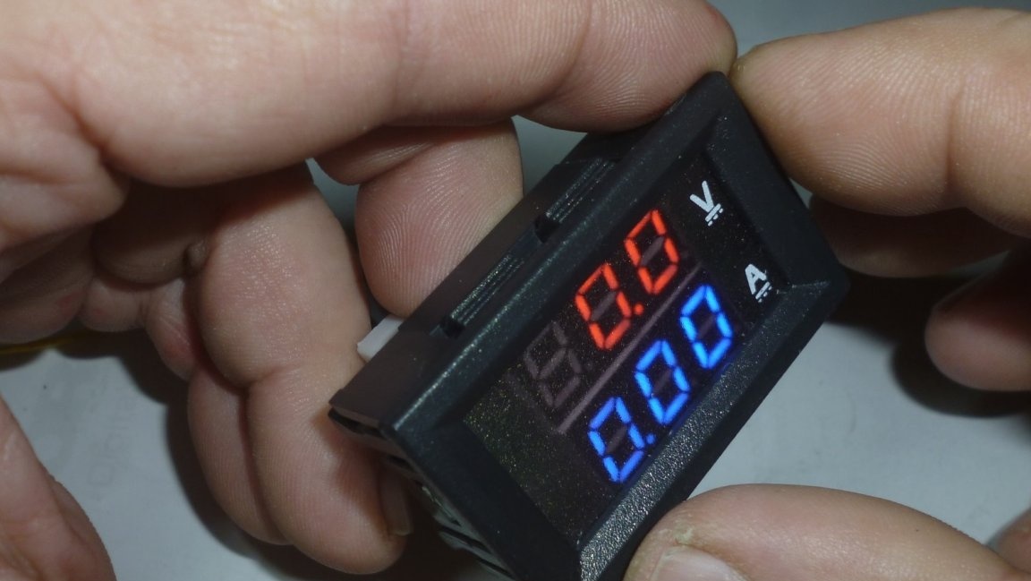
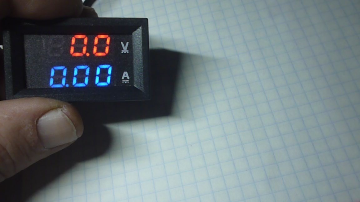
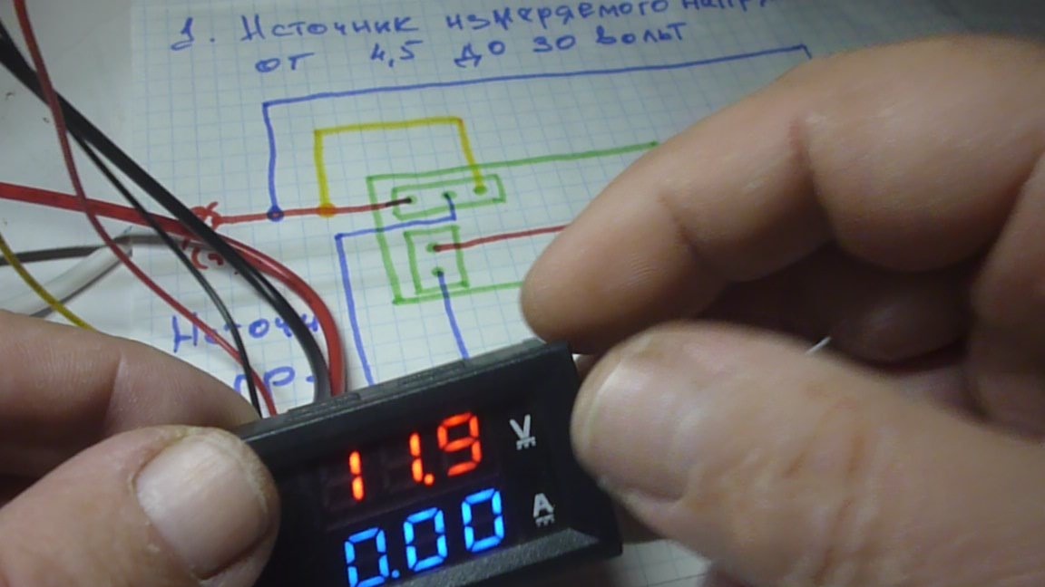
Today I want to tell you about one of the most popular, today, the Chinese measuring device, the DSN-VC288 volt ammeter. With operating parameters for measuring voltage from 0 to 100V and current from 0 to 10A.

Volt-ampere meter DSN-VC288, today, is one of the most popular and in demand, for measuring voltage and current strength, among ham enthusiasts and craftsmen. It is installed on various electrical appliances. The price of this device is very budget. In online stores ranges from 100 to 200 Russian rubles. What today, can be considered practically for nothing.

The DSN-VC288 Volt Ammeter is not well suited for assembling a laboratory power supply. Since the minimum step of the indication of the current strength, 10 ma. T.ch. you can put it in the LBP with not too high requirements for the accuracy of measuring the output voltage and current strength. That is, in a home power supply where very high accuracy is not required.

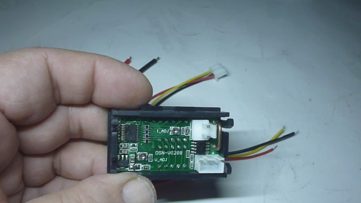
This device is connected very simply. This device has two connectors. A 3-pin connector serves to supply voltage to the device itself. All the same it electronic the system also loves to eat electricity, though quite a bit. The power supply of the volt ammeter is placed in a plug from 5 to 30 V. Contact for removing the measured voltage at the load. The measured voltage is the voltage that we will remove directly from the load from 0 to 100 V. The third contact is a minus. The 2-pin connector measures current in the circuit. It is connected to the circuit through the minus in series from the power source to the load. Also on the DSN-VC288 volt-ampere board are two tuning resistors. Which are used to calibrate the indication of the measured voltage and current, respectively.

Many who had to deal with the above mentioned measuring device are unhappy with the low quality of calibration tuning resistances. Here, as they say, who is lucky and who is not very.

As always, a little about safety. This is important, respect electricity, do not put your fingers in the socket, do not measure the voltage with your tongue and it will not touch you.

For those who like to watch, rather than read, I suggest watching, with pleasure, a video clip with a detailed description of connecting the DSN-VC288 multimeter.

Video clip instruction:


Tools for connecting a measuring device:


1.A soldering iron, preferably designed for soldering electronic circuits, rather than old basins.
4. A control tester that you trust. To check the accuracy of measurement, our device, voltage and current. And further calibration of the DSN-VC288 multimeter.
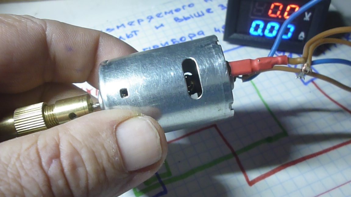
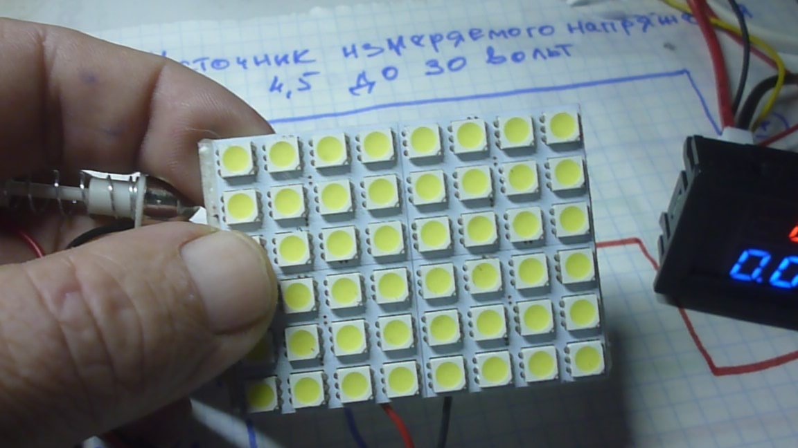
5. Any load for the control measurement (you can use the LED bulb of the appropriate voltage).
7. Stationery knife for stripping and preparing wires for soldering.

Consumables when connected:


1. Solder.
2. Soldering acid or rosin.
3. A set of wires for installation.
4. Insulation materials, electrical tape or thermal shrinkage.
5. A little electricity to test the device.

The order of connecting our volt ammeter DSN-VC288:


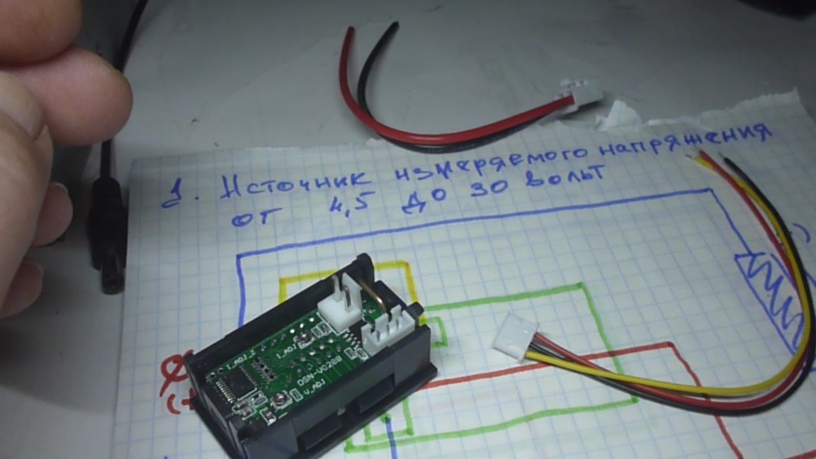
There are two schemes for connecting our volt ammeter.
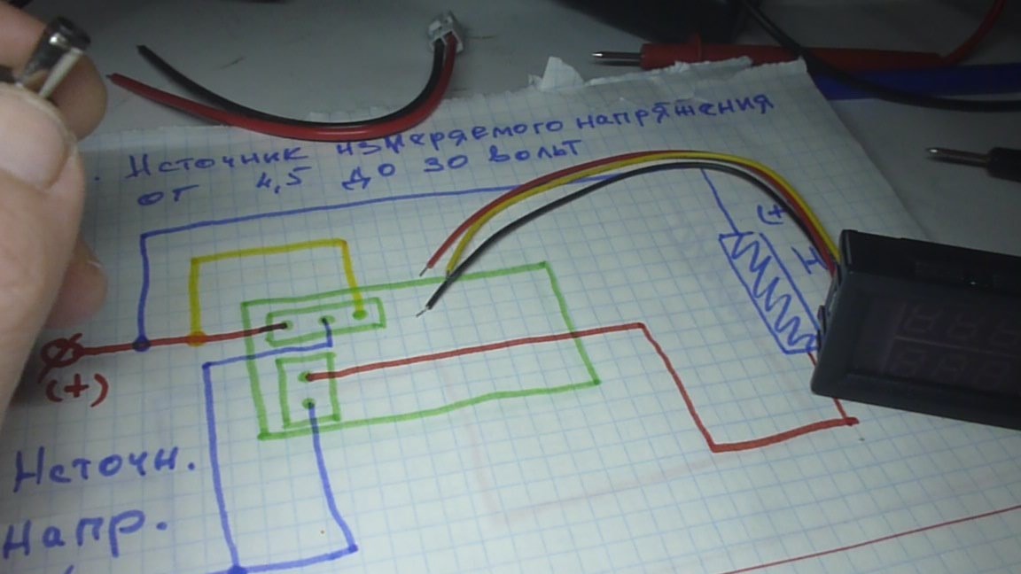
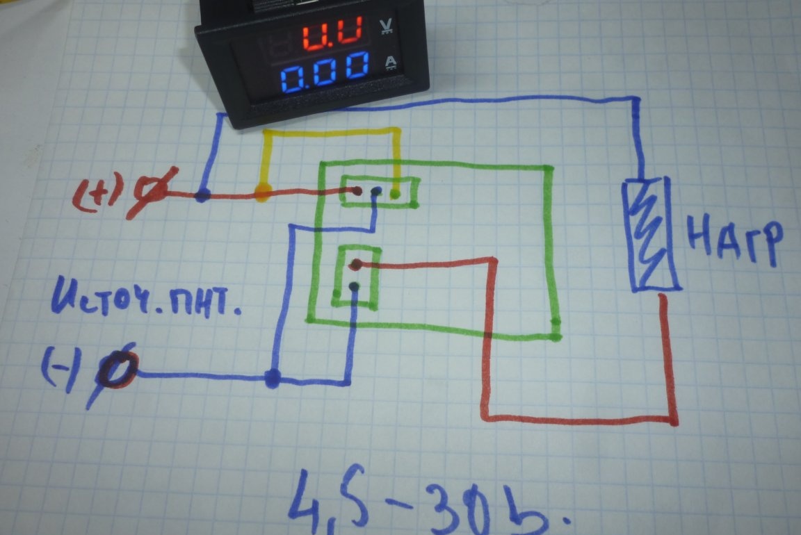
Scheme number one, connectivity. It is assembled if the measurement voltage fits into the plug of the used voltage of the multimeter. That is, from 5 to 30V.

In this case, the (+) device and (+) the measured load are powered at one point.
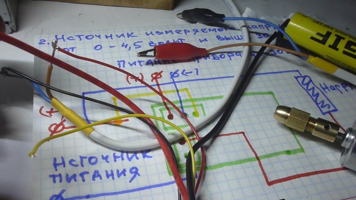
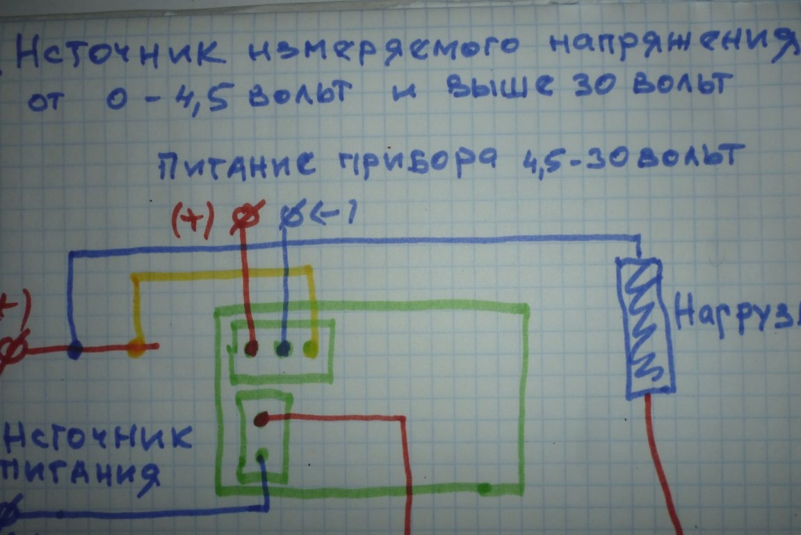
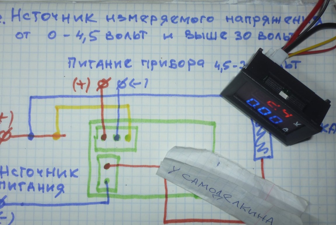
When the measured voltage drops out of the plug 5-30V (0-5V or 30-100V), the connection of the positive power cable of the device and the positive wire of voltage relief are connected from different voltage sources. If you supply voltage to the device less than 5V, the device will not work. If a voltage of more than 30V is applied, the device will fail.

Pinout device wires:

1. A block on three wires. I call her a stress block.
- Red. Plus the electrical power of our device.
- The black. Minus the electrical power of our device.
- Yellow. Positive wire for measuring the voltage at the connected load.

2. Block for two wires (Current block, due to the fact that they are connected in series and are designed for high currents, the cross section of these wires is larger than the cross section of the wires of the block to three wires).
- Black wire. Negative. Connects to a power source.
- Red wire. Negative. Measurement wire on load.

The connection diagrams of the Chinese volt ammeter are given below.
The first connection diagram according to the first embodiment. Second in the second.

Scheme 1.


Scheme 2.


If you want to see a very detailed step-by-step explanation of how to connect a Chinese multimeter model DSN-VC288, it is described in the video posted above, also in the YouTube version below the video posted a link to the online store. Where can I get this volt ammeter. Today, for 100 rubles.


For today, everything ... the road will be overpowered by the traveler ... Good luck!

Suitable for topic

Related topics

Add a comment

    • smilesmilesxaxaokdontknowyahoonea
      bossscratchfoolyesyes-yesaggressivesecret
      sorrydancedance2dance3pardonhelpdrinks
      stopfriendsgoodgoodgoodwhistleswoontongue
      smokeclappingcraydeclarederisivedon-t_mentiondownload
      heatirefullaugh1mdameetingmoskingnegative
      not_ipopcornpunishreadscarescaressearch
      tauntthank_youthisto_clueumnikacuteagree
      badbeeeblack_eyeblum3blushboastboredom
      censoredpleasantrysecret2threatenvictoryyusun_bespectacled
      shokrespektlolprevedwelcomekrutoyya_za
      ya_dobryihelperne_huliganne_othodifludbanclose
20 comments
R555,
In the order of humor.
I did something like that to order a charger for a car battery. The customer wondered why such a price. He said - the cost of parts, rewinding a transformer, manufacturing a case, etc. At first he ran into savings - "I will make a case myself, assemble it on plywood, ... maybe I will rewind the transformer myself?" etc. Then it was carried to reliability - put a thyristor 25 A, impregnate the transformer ... The very crown - from the pretty and not so ammeter he chose a tractor for 30 A, with three divisions on the scale and a wide arrow. To the question, why do you need a scale of 30 with your 55th? And the answer is for reliability. A week later, he calls - change the ammeter, it is inconvenient to configure. I remembered his boring, lost time and nerves and agreed - for extra. fee. We did not see each other again.
brnjh1,
If I think correctly, then by the accuracy of measuring current, the situation will be like this. When we measure sufficiently large currents, the accuracy is acceptable, for example, 4.25 A. But, when we measure small currents, the accuracy is very low. Example. 0.01 A. It can be 90 mA or 110 mA. And if the current, for example, is 15 mA, the device will not show anything at all. All this is because he does not have a switch for measuring limits.It would be surprising if such a switch were present in an inexpensive device.
Thanks to the author for the article. I have long seen this multimeter in different designs. There was no time, then too lazy to penetrate, to study the characteristics. And in the characteristics they can write anything. Another thing is when a person has worked with the device and tells what and how.

Frankly, I was surprised at the price. 100-200 rub. - one appliance and burning is not a pity for the park xaxa Joke. I’m probably going to buy 2-3 pieces myself. I already know where to put it.

Well, about the accuracy of measurement and so on, I will present my thoughts later.

R555,
By voltmeter. Judging by the number of digits of the indicator, accuracy is quite acceptable for most tasks. It will show, for example, 25.4 V. More precisely, there are other devices, for example, a multimeter. By the way, what does his voltage overload look like? The unit in the senior category lights up?
ino53,
At 5 A at a shunt of 30.2 mV, at 10 - 61 mV
Oh, they almost reached 75mV, maybe it would be about 12A, which was to be proved!
Why ... exceeding 10A ...!?
smile
Quote: Korolev
... I’m not sure that the internal shunt is 75mV, because 10A X 0.075V = 0.75 W, why would it be soldered? ... scratch

Now I ripped out a shunt from a dead Chinese, sequentially hooked C5-16-5W-0.1-1% to control the current and turned it on. At 5 A on the shunt 30.2 mV, at 10 - 61 mV, the shunt is quite warm. One cannot speak about the accuracy class, but the order is consistent.
... Damn, there is no time to philosophize ...

Quote: Korolev


... And let's imagine the real picture: a current flows in a certain circuit, the value of which must be measured (controlled) by including two shunts in the circuit break, one of which with unknown parameters ... scratch

Repeatedly did ammeters with incomprehensible shunts on the memory - if dial, then a new scale, in series with the exemplary and went to put risks, 1 A 2 A, etc. For digital is more complicated, you need a conversion table or formula. And another option is your shunt.
ino53,
Korolev will give out something smart, as has already happened, and I will sit all from myself from head to toe in
In order to give out something smart, you still need to take it somewhere. I sincerely regret that my attempts to give out something clever, in fact, turn out to be ... well, this very thing ... But seriously, I think that the current flowing through a closed circuit is deeply purple, how many mV falls on which element. And I'm not at all sure that the internal shunt is 75mV, because 10A X 0.075V = 0.75 W, why would it be soldered?
Imagine the opposite picture
And let's imagine the real picture: a current flows in a certain circuit, the value of which must be measured (controlled) by including two shunts in the circuit break, one of which with unknown parameters ... scratch
Quote: Korolev
...., and through the internal shunt, a current will go much higher than 10A ...
... prone to self-drinking from overheating .... Well, something like that ... scratch

Why ......!?
Imagine the opposite picture - we apply a nominal value of 75 mV to the shunts connected in parallel. 10 A will go through the small shunt, 200 A through the big shunt. A current of more than 10 A cannot go through the small shunt at 75 mV, but 200 will go through the big one (I wrote and I think now Korolev will give out something smart, as has already happened, and I will sit all over yourself from head to toe in ..... bad )
As for the self-extraction of the shunt - once it happened, I screwed an insulated winding wire on it with a sort of brush, it made it easier for the poor smile
brnjh1,
the flamaster caused risks and numbers
This is not necessary, there are two tuning resistors on the board that allow you to adjust the readings of the device to some extent, one by current, the other by voltage. yes
ino53,
What I mean - with the parallel connection of shunts 10 and 200 A
As always, I could not clearly articulate my thought! When the shunts are connected in parallel, the currents will be distributed inversely to their resistances, and a current significantly exceeding 10A will go through the internal shunt. Moreover, our Chinese comrades can make these shunts from anything.These shunts during prolonged operation at high currents (up to 10A) are prone to self-drinking from overheating. In addition to overheating of the circuit elements, which is already hot, this is fraught with the passage of large currents directly through the circuit, in the absence of external and self-drinking internal shunts! Well, something like this ... scratch
Quote: Korolev
... Yes, and I gave advice stupid, ill-conceived .... .... no way the current will not be divided in half! sorry

Who said stupid? Count.
Small shunt - 75 mV / 10 A ... R1
Large shunt - 75 mV / 200 A ... R2
With a parallel connection, the current will go (and the power too) is inversely proportional to the resistance (Kirchhoff, if I do not confuse). What is the point? With parallel connection of shunts 10 and 200 A, the total deviation will be at 210 A, i.e. error of 5%.
Author
Quote: Korolev
the internal shunt will greatly heat the entire device

Again, I crookedly put it, the shunt is external, its own conditional calibration. We take a reference device, measure the current, then measure it with a verified ammeter with an external shunt. We recalculate the difference and derive a correction factor. For a good ammeter, this is a milliammeter, it's all about the shunt. In the good old days, they took a dial milliammeter, put a shunt in parallel, checked and put risks and numbers on the flaster. The amperage was measured by them ... It turned out long, but I hope it is clear ...
brnjh1,
I meant the correction factors when installing a third-party shunt ...
No, there, at high currents, the internal shunt will greatly heat the entire device. Yes, and I gave advice stupid, ill-conceived. Too different shunts in terms of both constructiveness and resistance, in no way can the current be divided in half! sorry
Author
Quote: Korolev
without external shunt

I did not mean without a shunt, I mean correction factors when installing a third-party shunt ...
brnjh1,
In order not to bathe, you can simply calculate the coefficient and recount, if the device is only for control.
No, high currents without an external shunt will simply destroy the device.
Author
Quote: Korolev
First, try to find a standard shunt.

In order not to bathe, you can simply calculate the coefficient and recount, if the device is only for control.
Wit, First, try to find the standard shunt 200A, 75mV, for example 75ShIP1-200-0.5, and connect it parallel to the built-in meter. If the measurement results are underestimated by half, solder the built-in shunt. And it’s better to drive something like: “connecting the shunt to the DSN-VC288” in the search engine and may Google, the Wise and All-Knowing, be with you or any other search engine! smile
Author
Quote: wit
how to make a 200A meter from this device

If it’s very simplistic, then put a shunt resistance in parallel with the ammeter, a shunt ...
Wit
Tell me how to make a 200A meter from this device
Guest Maxim
Thanks, it works.

We advise you to read:

Hand it for the smartphone ...