

Greetings to the masters!
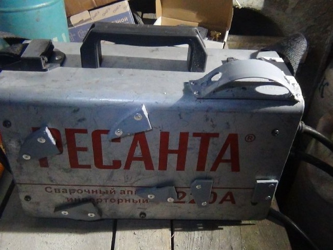
After the torment, let's say, I decided to make a body kit for the welding machine. The torment was that, working at heights, it was not always convenient to take the electrodes with your hand in the hood and try to put them in your pocket or waist bag, they constantly got enough sleep, etc., and the hammer was constantly lost even if I worked in the workshop. And also in the workshop I had to look for packs of electrodes, then they fell somewhere, then I put material on top, etc.
The idea came to my mind to attach everything to the body of the welder ...
While work on the street was not possible due to weather conditions, but could not sit idle, took up homemade.
Tools and materials:
- Angle grinder (grinder)
- cutting wheels for metal
- sewer pipes F40mm (2 pcs.)
- plugs for sewer pipes Ф50мм (2 pcs.)
- plugs for F110mm sewer pipes (4 pcs.)
- exhaust rivets 3.2x10; 3.2x6; 4x10
- riveter
- drill bits for metal 3.5 mm; 4 mm; 16mm
- screwdriver or drill
- piece of partition drywall profile 50x50
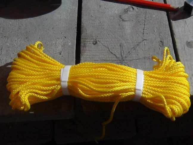
- clothes line
- soldering iron
- Soldering Station
- tape measure or ruler
- pencil, marker, awl (used to draw the outline, it was more convenient)
- 4 mm galvanized washers
- hammer
- vise or anvil
Step 1: Material and placement on the case.
Before undertaking and doing what is intended, it is necessary to take into account the dimensions of the apparatus body, the dimensions you need to know for the following:
- dimensions should be compact
- placement should be on one side
- during operation, use of the body kit should not create discomfort
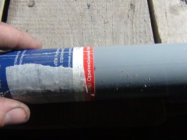
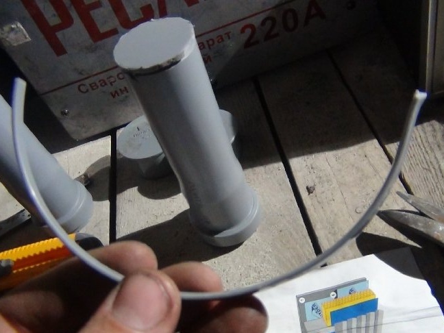
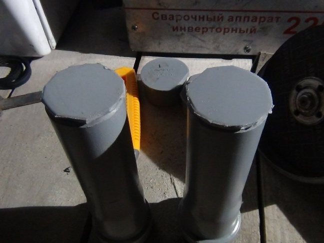
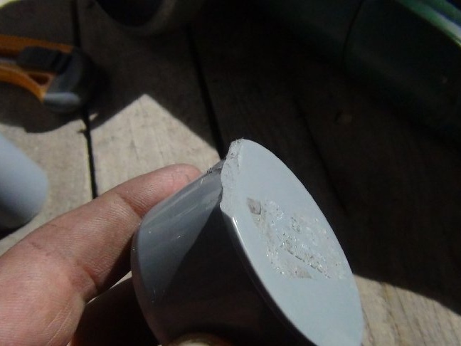
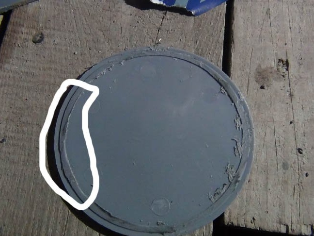
For the tube under the electrodes, the most optimal is a pipe, sewer 40 mm is quite suitable for this. It has its advantages: plastic is strong enough, cheap and most importantly lightweight.
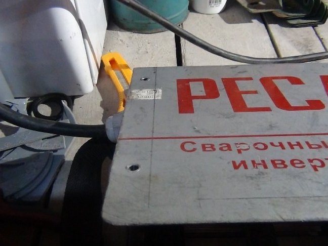
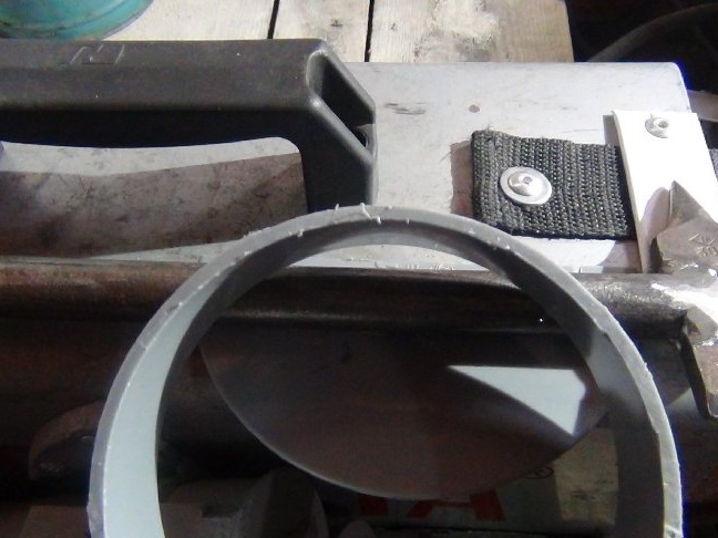
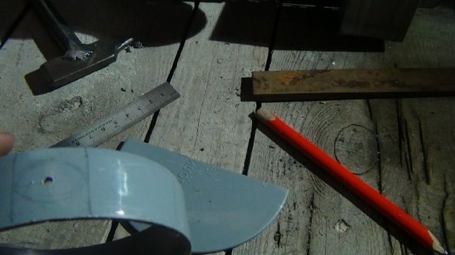
Having 50 mm pipe cuts on the farm of sufficient length (just to determine the location), in order to understand how the tube itself will be located, I used them to determine the place on the body. To measure the dimensions with a tape measure, I considered it unnecessary, because to determine in fact it is more convenient when you already know what you will be doing.
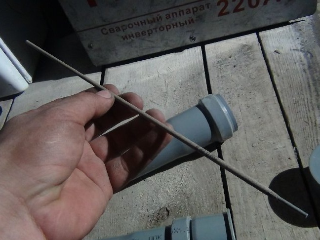
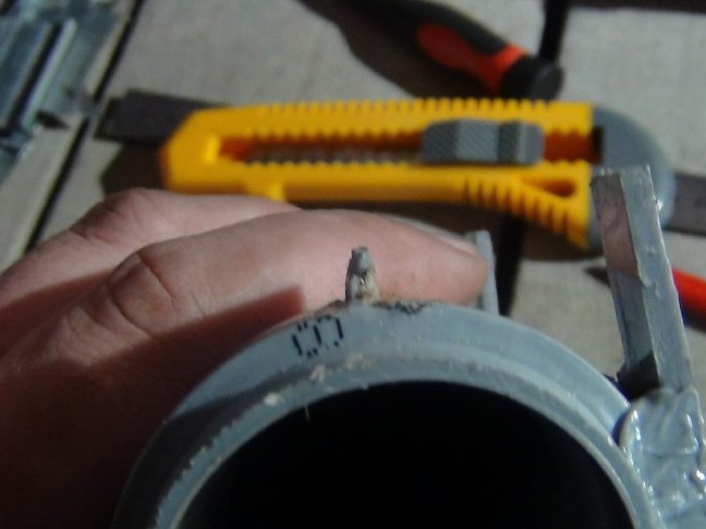
While mastering the work with welding, I was convinced that the electrodes cut in half are more convenient than in the whole form.Now I constantly cut them into two parts of 17.5 cm and on the cut off parts I knock down the powder with a hammer (I do not remember what it is called correctly). A 35 cm long tube for the whole electrode could not be compactly placed on a tin casing so that other ideas would also be placed side by side.
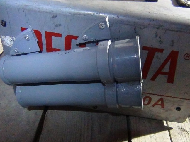
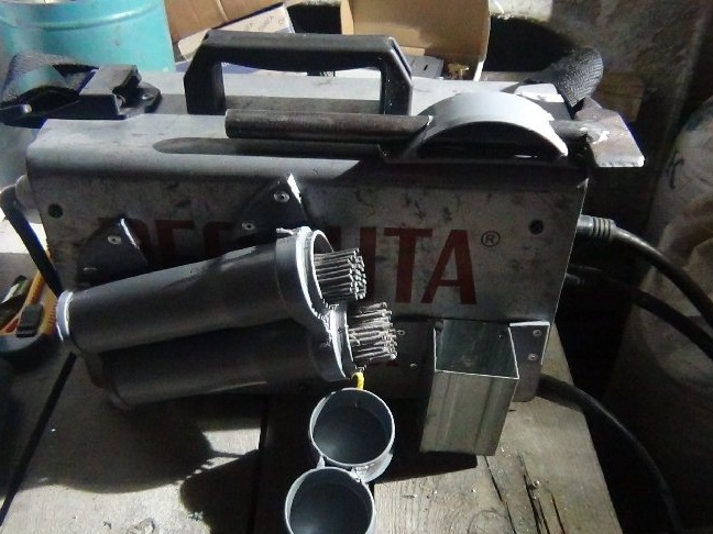
Step 2: Tube for electrodes.
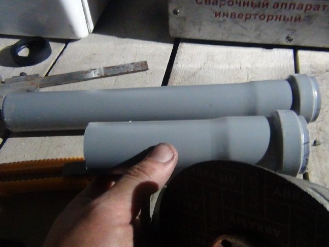
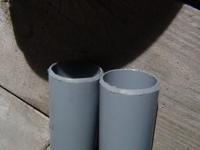
Having decomposed the electrodes initially in the 50th and 40th pipes, I realized that the 40th pipe is more capacious, i.e. to make a tube from two 40s pipes was better suited in size than from one 50th. But the tubes were needed with a bell for connection (I will explain why), and since I had trunks without sockets, I had to go and buy. I also had to buy two plugs for the 50th pipe, of which I will make a cover so that the electrodes do not spill out if the welding is tilted.
I bought tubes of 25 cm in length, I came across 15 cm, but for some reason they were not on sale. I will cut off not 17.5 cm from the edge, but a little less than 17.5, based on the calculation that the cover also has a depth of almost 2 cm. I put the future covers on the 40 mm pipe sockets and form the cover.
I cut off less so that after cutting the excess at the pipe, the electrodes protruded over the edges at the end of work on the tube. It is better to take the electrode immediately than to try to find it with your fingers inside.
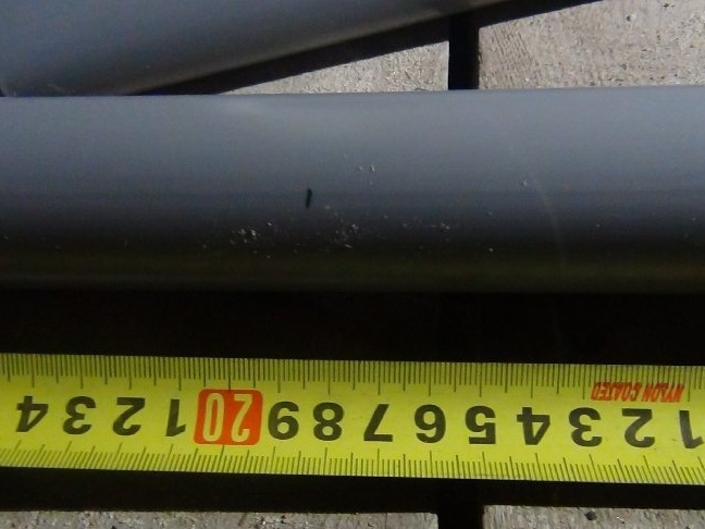
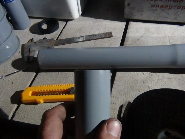
The length is 17.5 cm, and measured 18 cm (0.5 cm margin) from the rib on the plug itself, and from it made a mark on the tubes themselves.
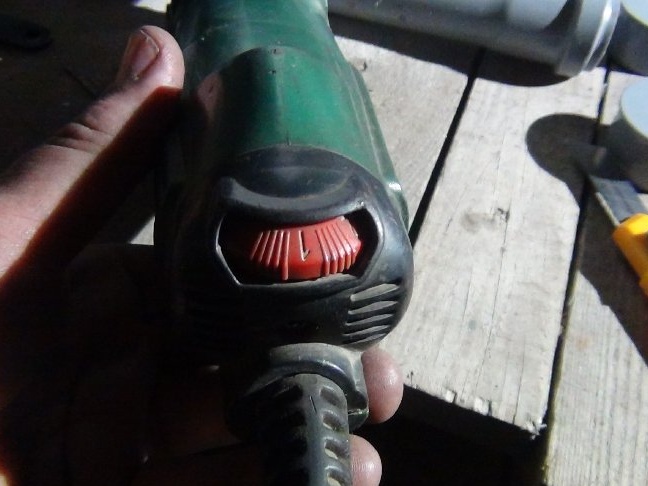
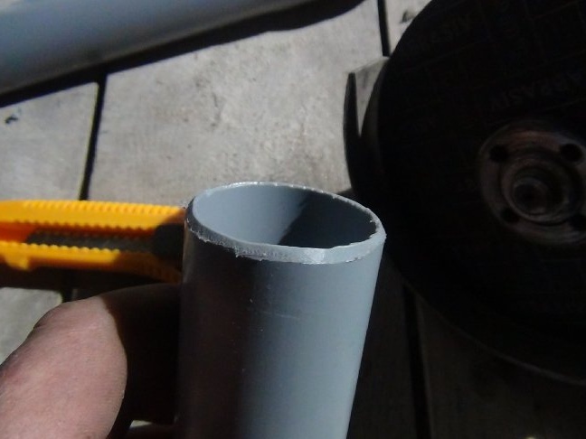
I trumpeted the pipes along the mark with a sheet of paper. I wrapped it around the pipe, connected the edges of the paper and glued these edges with duct tape, cut it off with the ears, it has a speed regulator on it and I did not have to cut the plastic with an office knife.
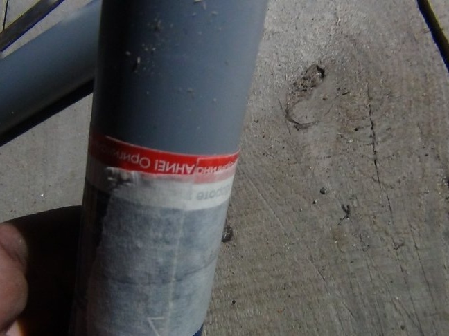
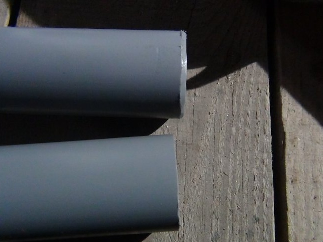
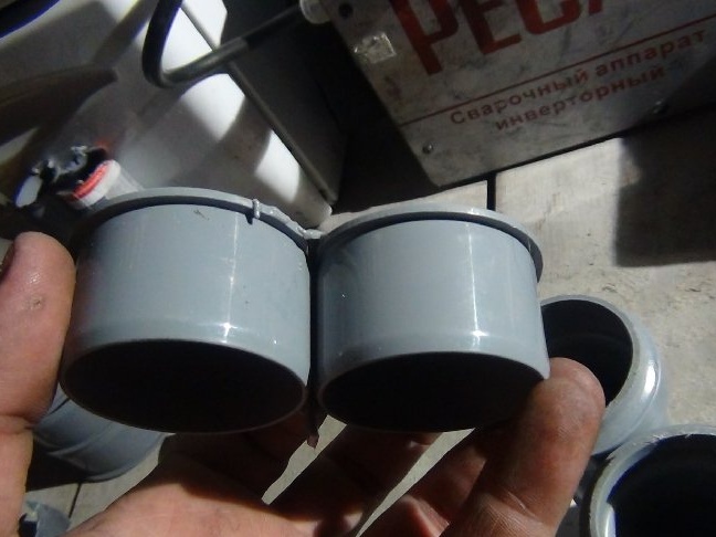
As the tubes were facing, I decided to return the chamfers, they will be required so that in the future it was possible to solder the bottom.
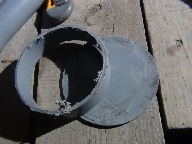
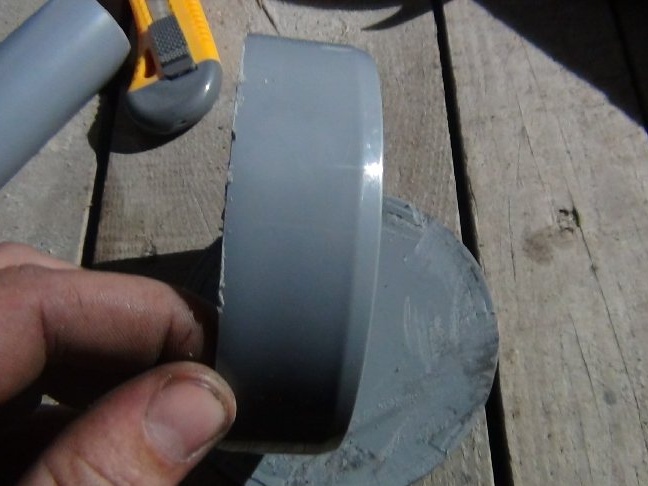
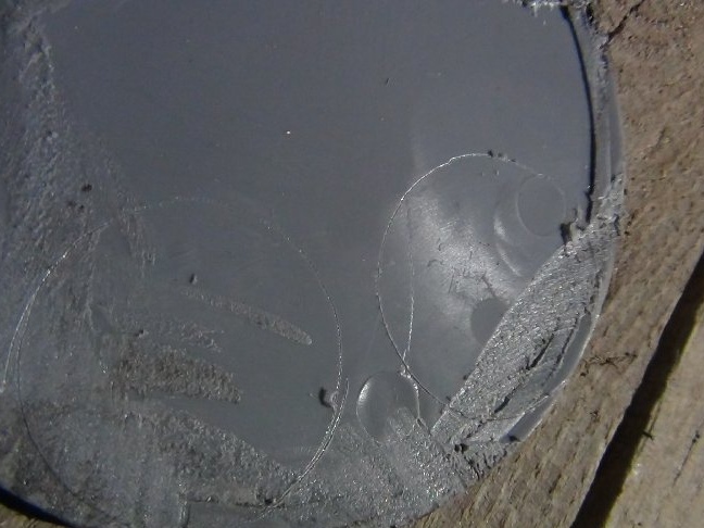
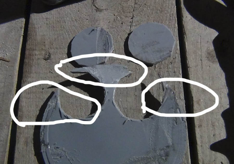
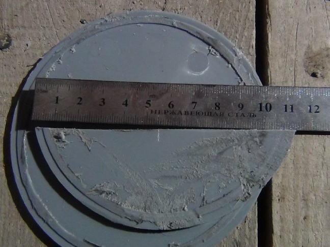
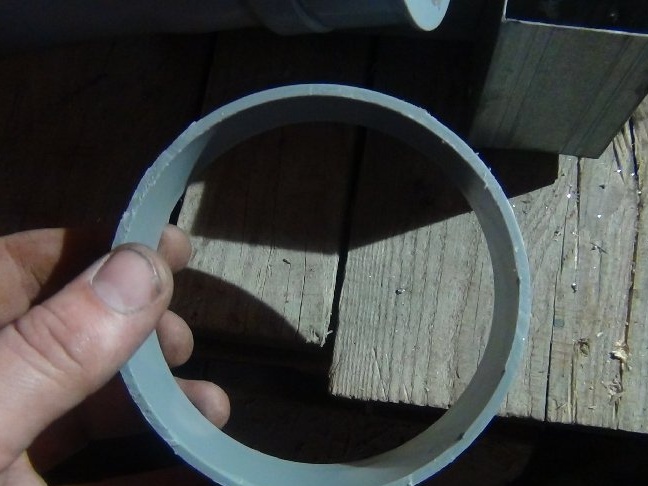
Plastic for the bottom of the tube was cut from the same plugs only for the 110th pipe.
Somewhere I had pieces of the same plastic, but I was too lazy to look for them, so I decided to purchase these plugs. To get a flat plastic for the bottom from them, I cut a ring from these covers.
The remaining rings will still be needed, I use them as bars for soldering, having previously cut them to a width of 3-4 mm with metal scissors.
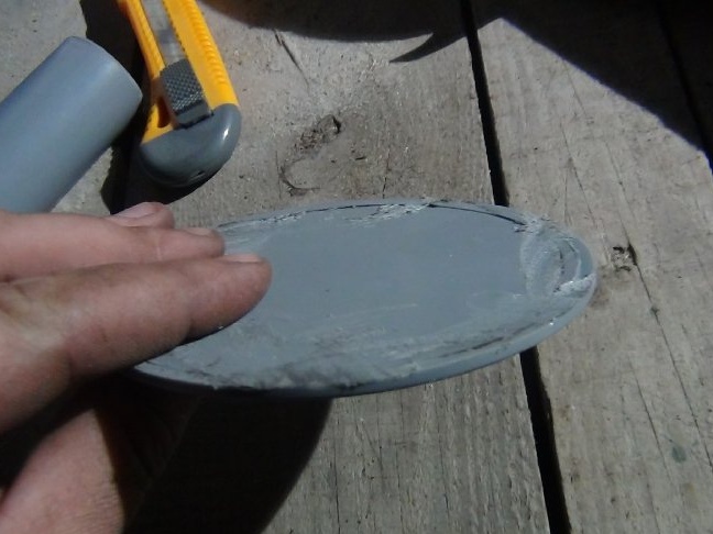
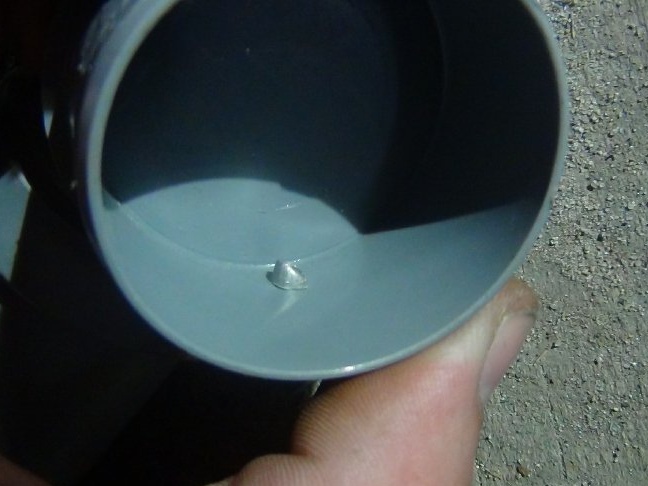
Not wanting to spend time marking with a marker, set the cut-off pipes on plastic and scratched the circumference of the contours with an awl. Then cut out with scissors for metal. As a result, two bottoms, it remains to solder them.
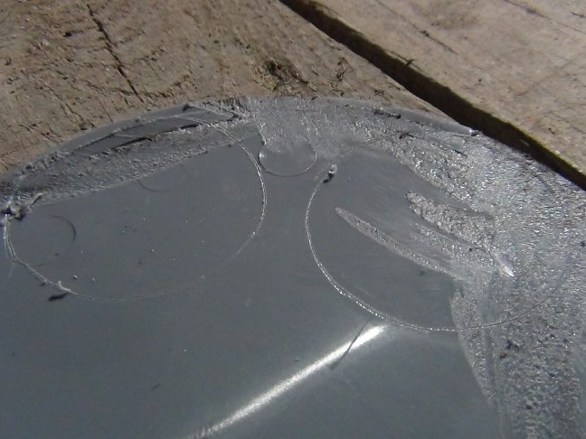
When using a soldering station, i.e. solder with a rod, made point tacks with an ordinary soldering iron along the bottom and the tube, these points will hold the bottom in place and will not allow the wings to move when soldering with a plastic rod.
It turned out very personal, smooth the rough edges with an ordinary soldering iron. Almost salable.
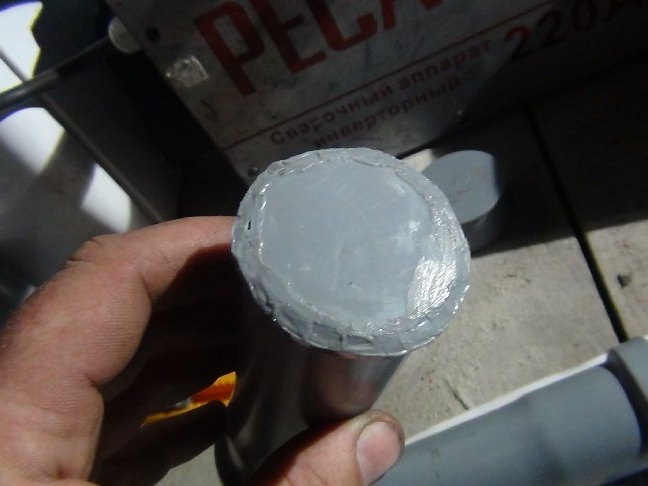
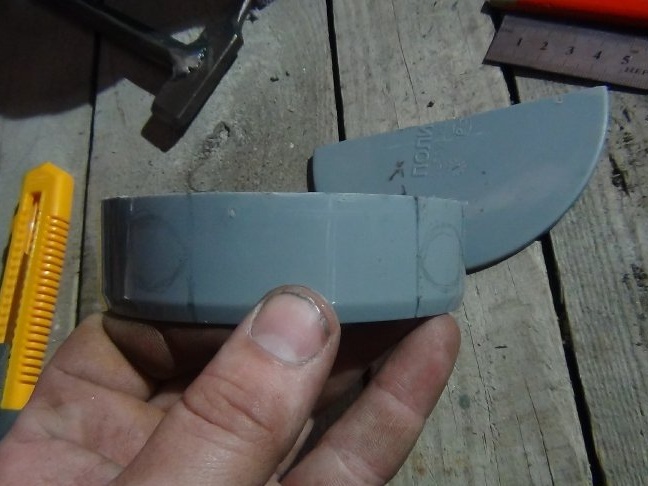
Almost everything, but it remains for small - the cover
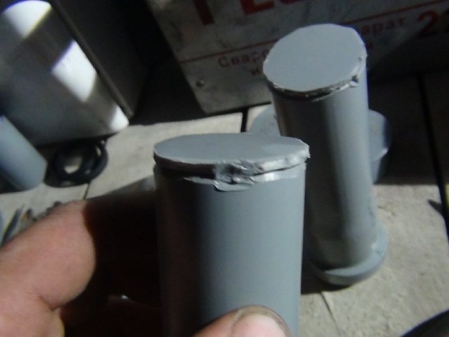
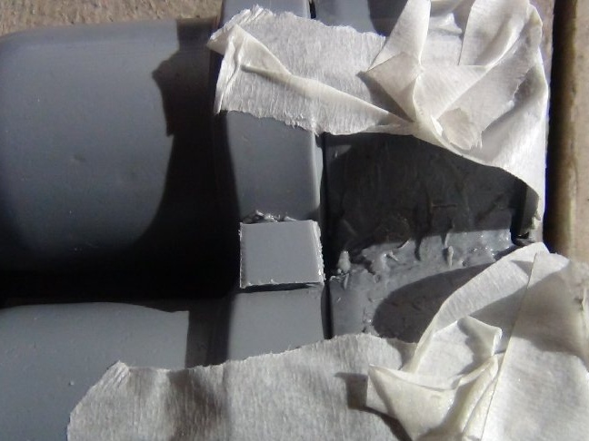
The protrusions on the caps will not allow you to put on the tubes as planned. We'll have to cut them on one side and also cut the chamfer. This work will facilitate their soldering in the future.
The decision to cut is so conditioned by the fact that it is better to cut the ribs and tubes closer to each other than to leave everything as it is and to catch the millimeter between the tubes. But the dimensions of the tube are limited by the dimensions of the wall of the tin casing of the welding.
Between them they were soldered by pieces that remained after cutting the bottoms. Trimming is no longer suitable, but for such work just.
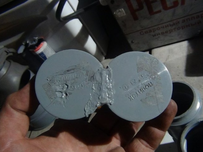
So that the lid does not break in the soldering place where the ribs were, I decided to also solder it on the sides. The stronger the lid, the longer it will last, and a further idea requires that it be so soldered otherwise it will break.
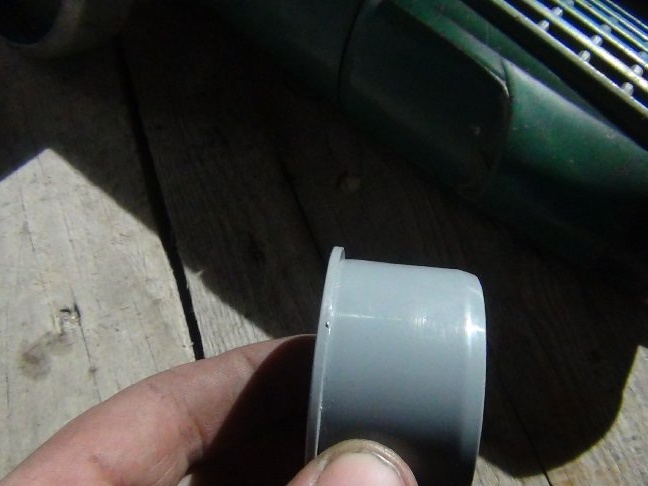
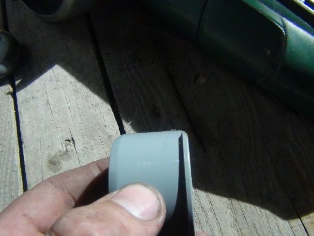
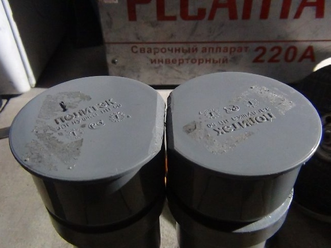
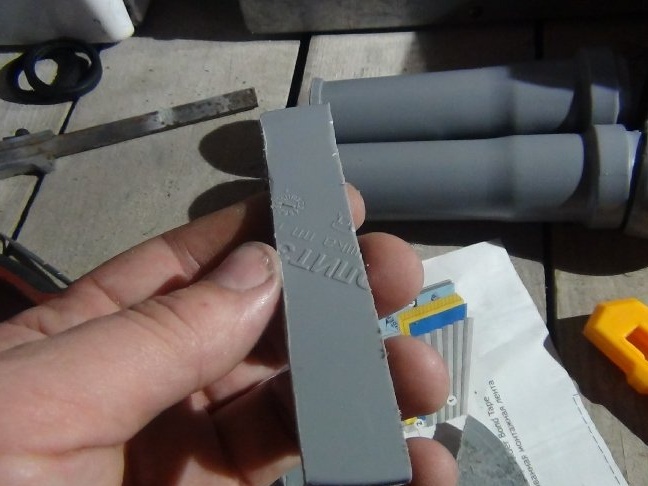
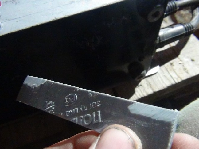
The production of these pipes is done by molding, if I am not mistaken with the name of the process.
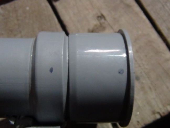
Pipe extensions, inside of them are rubber seals inside, have an uneven shape. It will have to be grinded, otherwise the manufactured cover will not be worn on the bell and you will have to redo one thing.
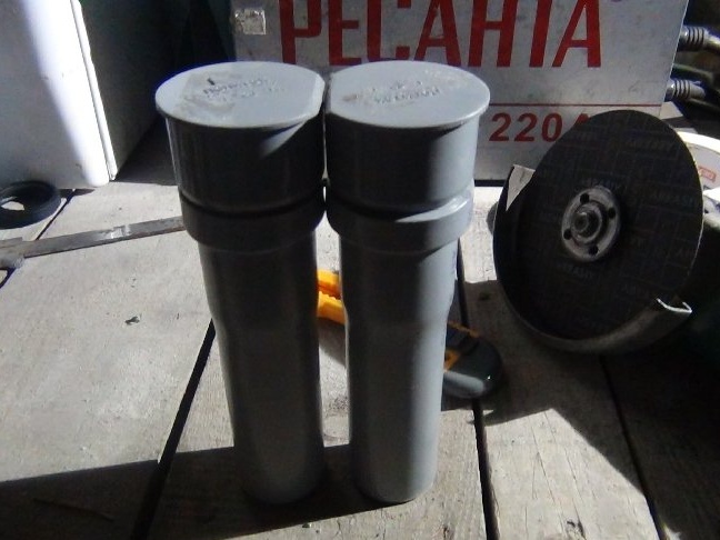
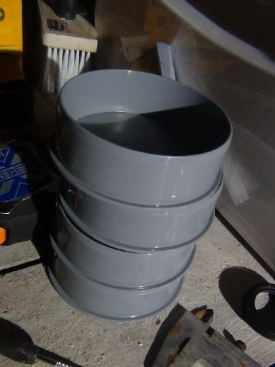
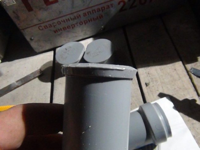
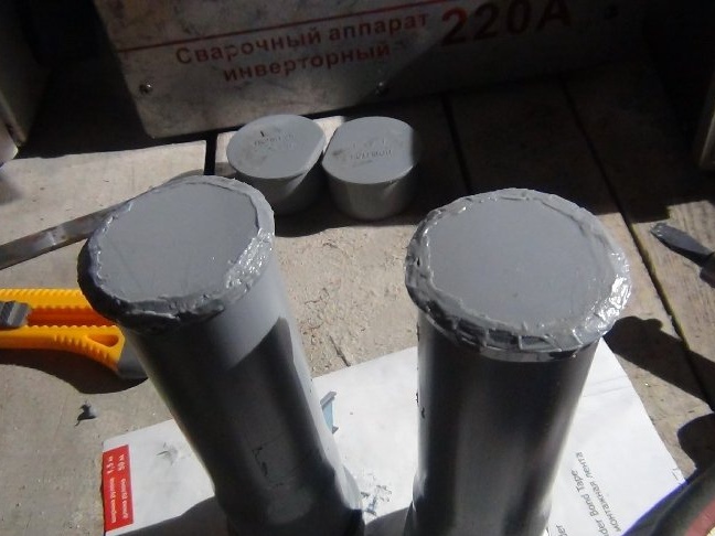
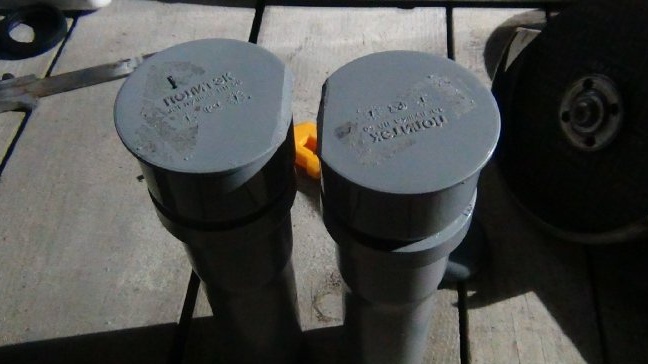
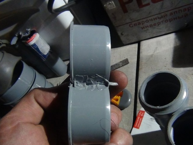
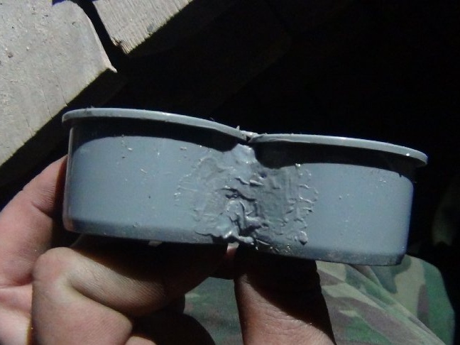
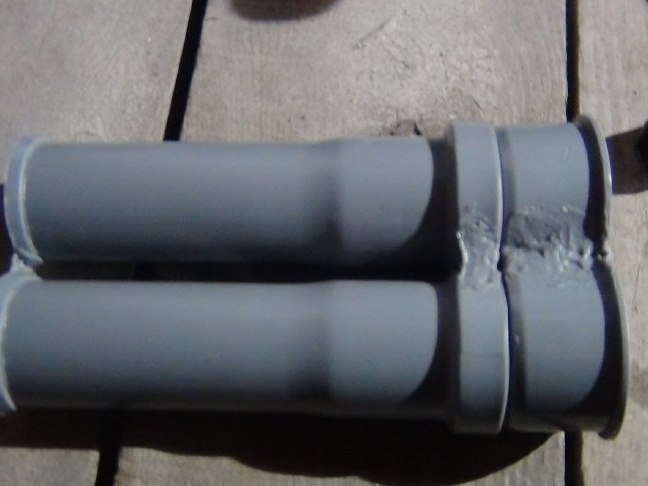
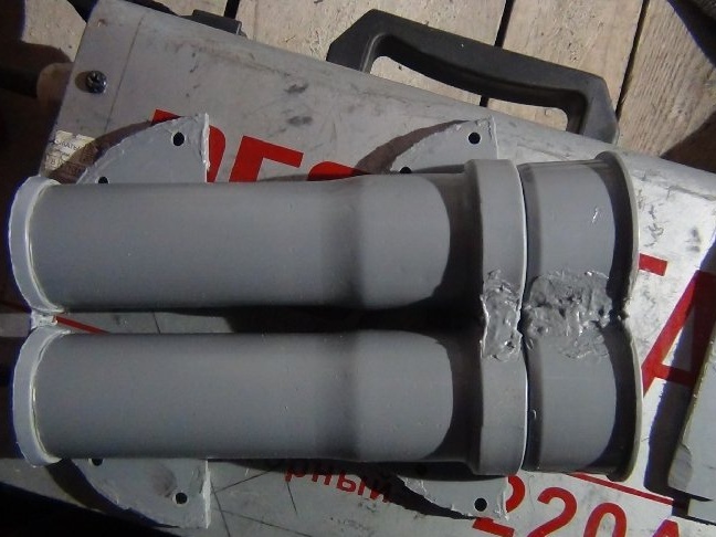
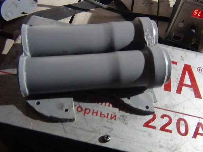
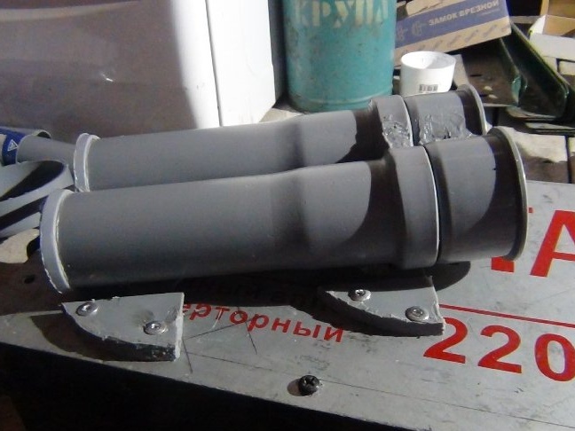
After this work, we proceed to the merger of two pipes into one tube.
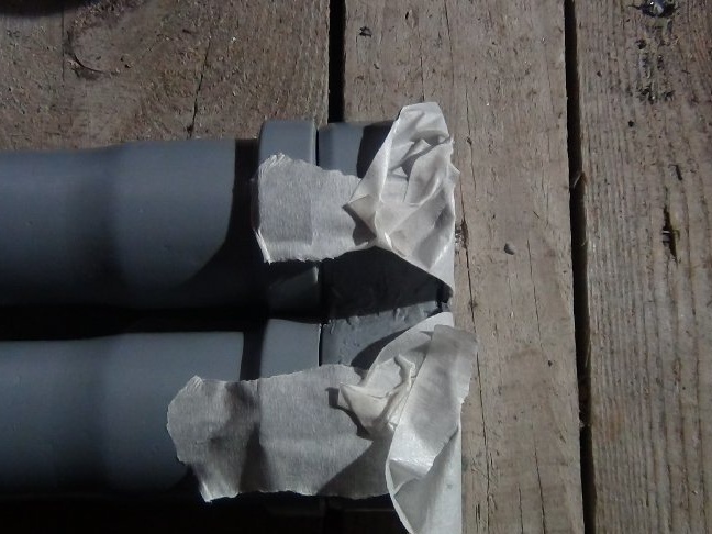
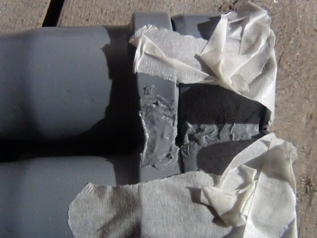
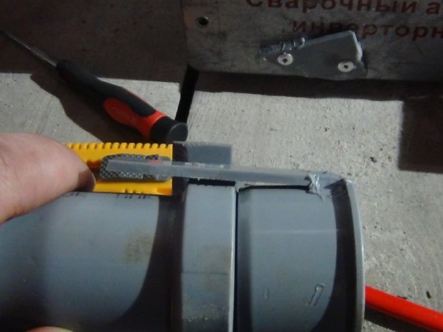
Before soldering the tubes together, it is necessary to put on the lid on them and fix them with tape, this will not allow the tubes to move relative to each other during the soldering process.
While working with plastic, there are many scraps left, but in order not to throw out the material, in fact, we put it into business, cut these scraps into pieces and put them on the contact of the sockets, and since there was no point in soldering the station (only 1-1 , 5 cm) soldered with a soldering iron. At the bottom he did the same.
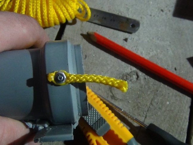
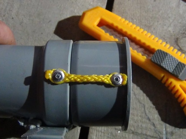
I had to think about the hinge of the lid, there were facts that it should not open in one direction, otherwise it would not be convenient for her to use (it will be clear why). To attach it to a spring, a piece of rag or a swivel would not be aesthetically pleasing, so I decided to use a piece of polypropylene cord. On this cord, the lid can open and slide in any direction, this idea turned out by the way, the lid can be opened and refilled for the container with the remnants of the electrodes, I called this container an “ashtray" (the most logical name), and it will be located just under the tube .
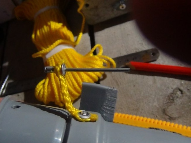
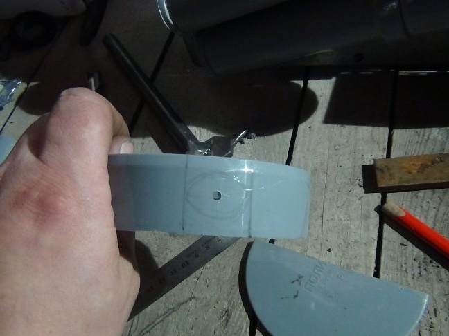
Until I removed the tape, I marked the drilling places for rivets 3.2x6 mm.
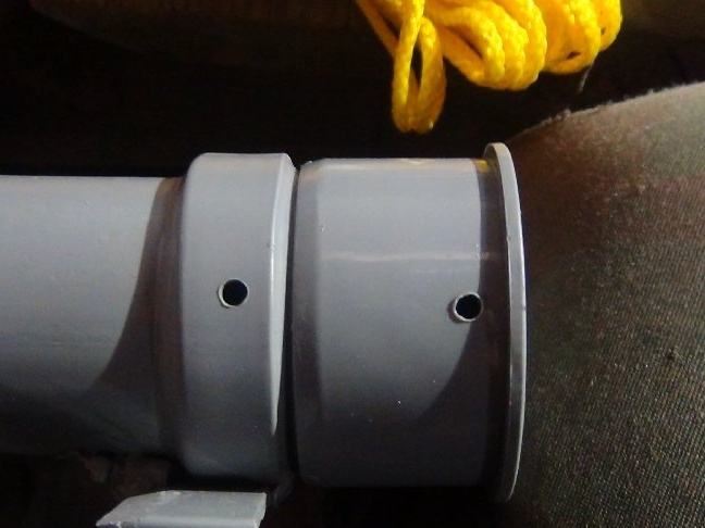
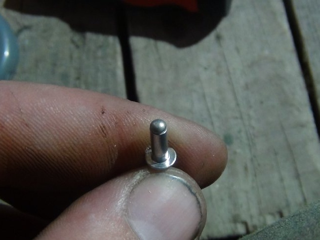
After shaving with a knife, the shaggy ends of the cord were treated with a soldering iron. Then, to install the rivet, he pierced it with an awl and pulled it. Before installing the rivets in plastic, it is better to put the washer on the back side, it is worth doing, because rivets are rivets and during installation can break the plastic.
The lid will not be a lid if it hangs.
It was necessary to come up with a lock, but simple, without a key. For convenience, it is better to make it possible to open with one finger.
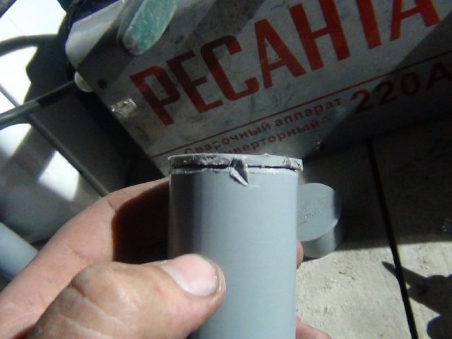
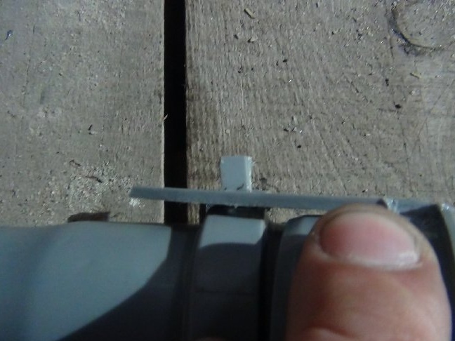
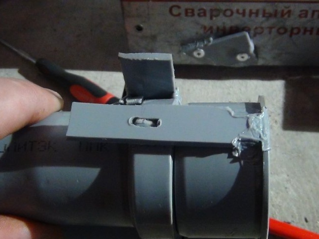
Made a simple latch lock of the plate.
The plate was cut out about 6 cm, it was made this length specifically so that there was a place to pry a finger open and leaned it against the edge (see photo).
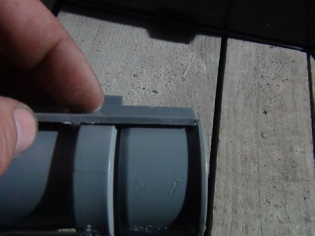
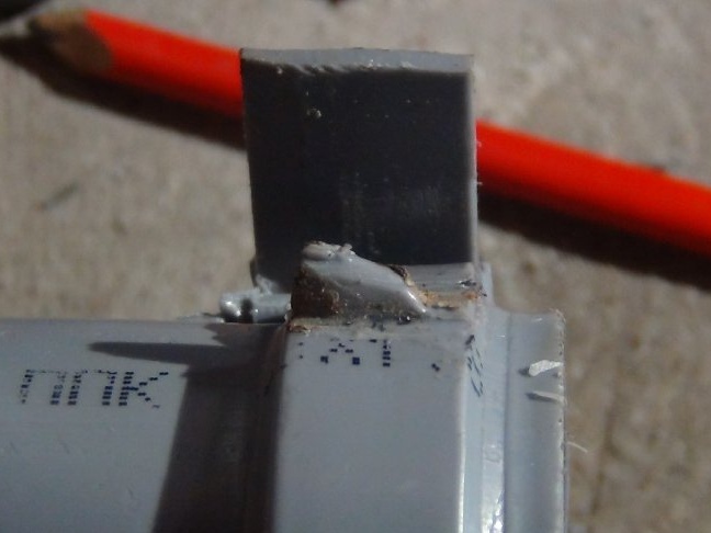
To prevent it from breaking off during the first tests, it was soldered both along the edge and on the sides, after such a soldering it began to function as a spring.
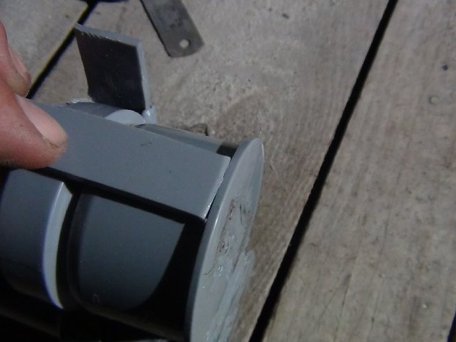
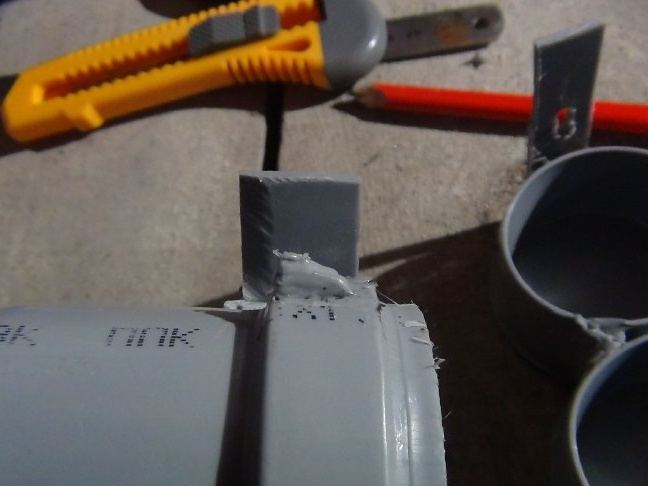
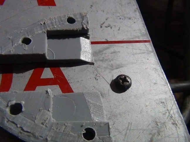
Instead of a loop, this is not a lock, made a small ledge similar to a shark fin. To do it, you need to drill through the plate into the pipe, set the direction. If this “fin” is soldered to the surface, then it will break off, and if it is inserted into the hole and melted from the inside, it will be better to stick, I did so.
The plate for the fin was cut off 1 cm long.
All the same, it disappeared from the outside.
Now we give it the “fin” its shape, soldered it with a soldering iron and smoothed the melted edge. Bevel made towards the lid, now everything works like a latch. But on the sides of this nozzle I had to modify the file so that the plate was put on without problems.
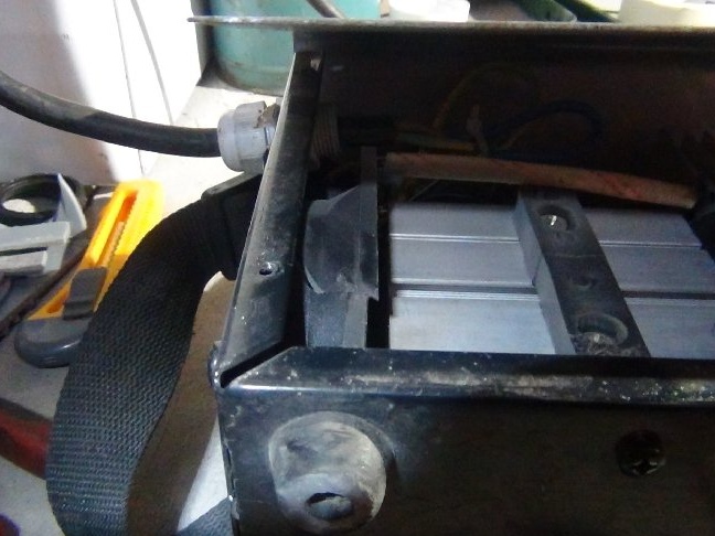
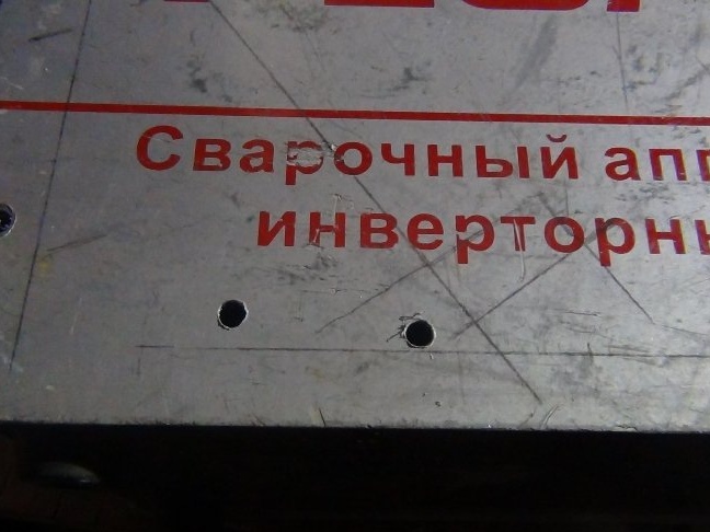
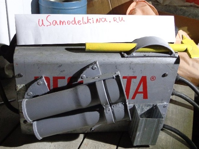
Step 3: Attaching the tube.
Before drilling, it is necessary to remove the casing so that the chips do not get on the circuits and contacts.
In an extreme case, you can unscrew the wall and put under it either cardboard or thick paper, as I did.
I went through many mounts in my head, but decided to stop on what I will describe further.
The fastening was not required very large so as not to interfere if the tube was removed, because I do not always work at height and there is no need to constantly keep the tube on the device’s body.
As a result, the further decision turned out to be the topic, i.e. most suitable.
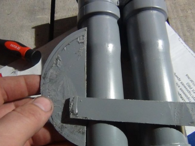
The principle of fastening as a valve or bolt.
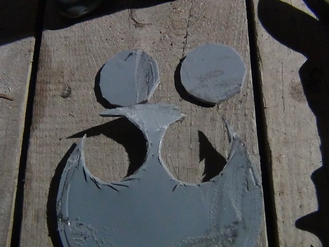
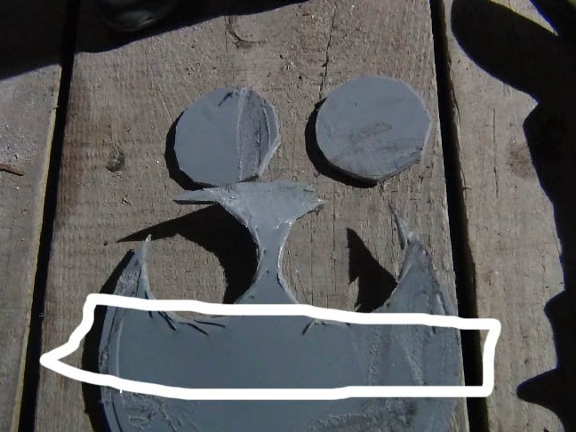
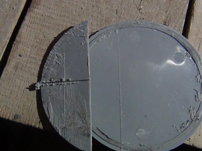
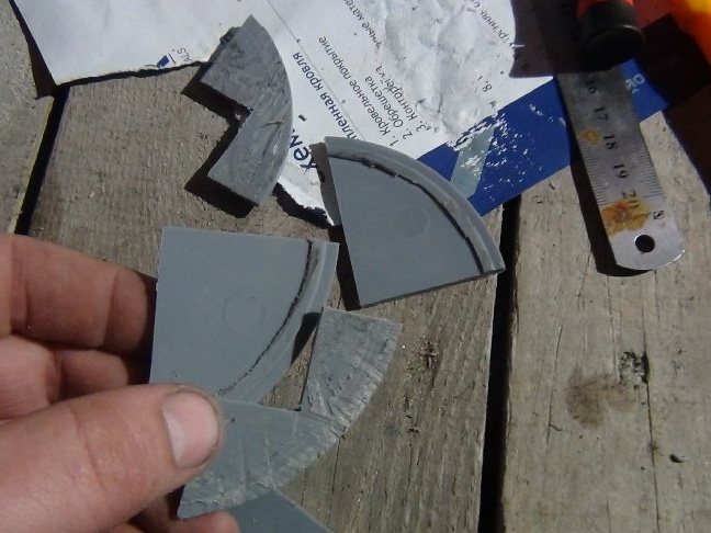
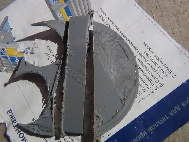
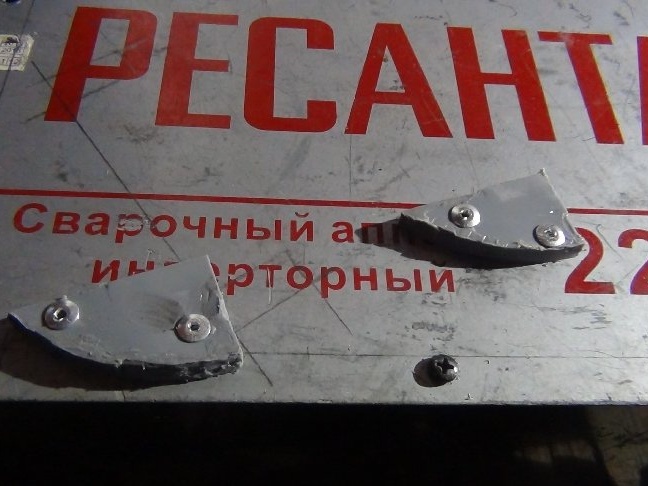
I cut out all the elements from the 110th plugs.
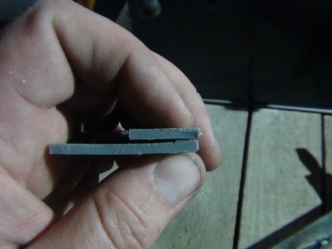
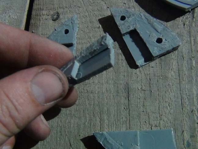
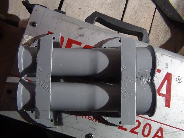
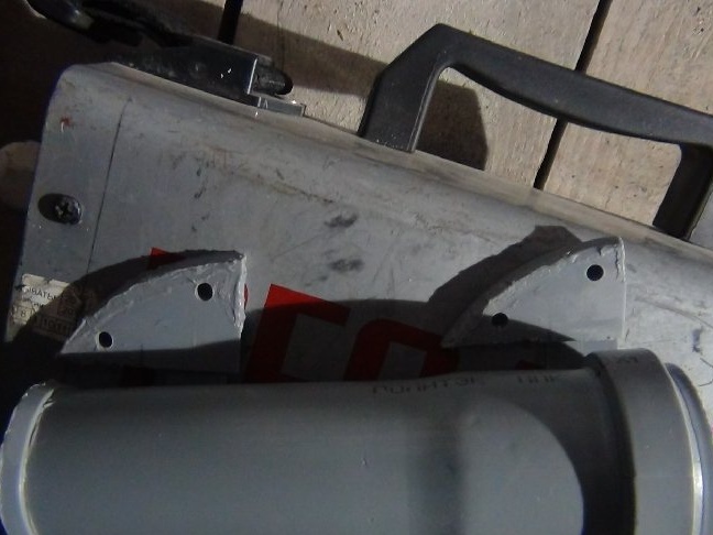
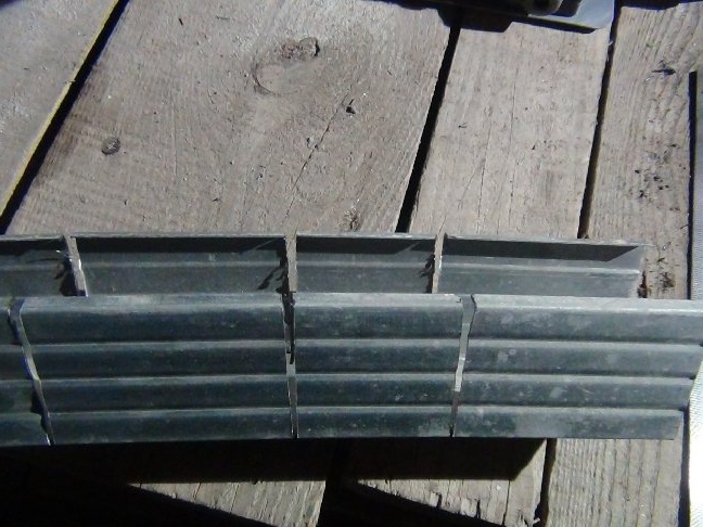
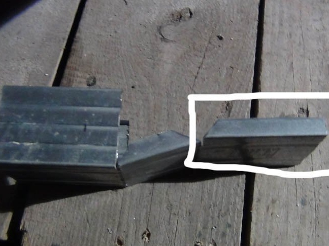
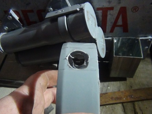
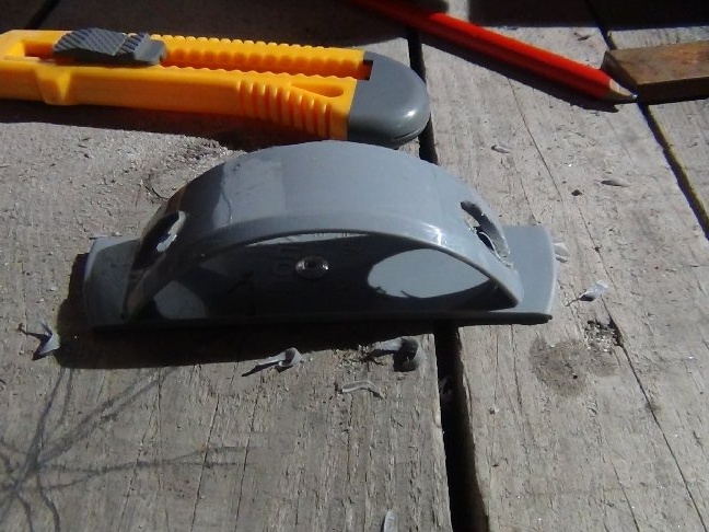
The mount is designed like a pocket. To do this, you need to cut two identical parts for one mount, in one of them a quarter will be cut where the bar-bolt will be inserted. The one in which the part will be cut will be adjacent to the body. Such parts will need 4 pieces.
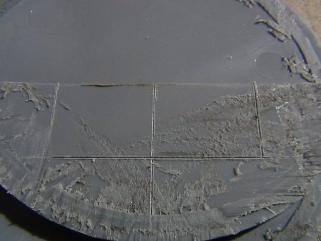
In order for the deadbolt to fit into the latch without problems, a gap of 1 mm must be made between the parts. When sawing off the ring from the 110th plug, there were protrusions, they were useful.
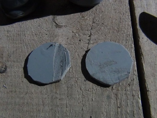
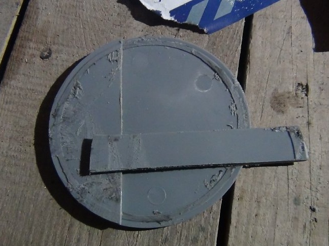
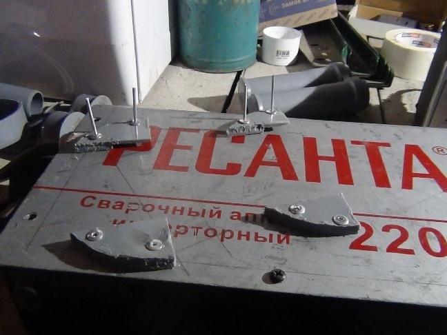
I connected the two parts of the mount and simply soldered along the edge with an ordinary soldering iron. As a result, we have a mount for the bottom of the tube. He made all the parts in a similar way (photo below).
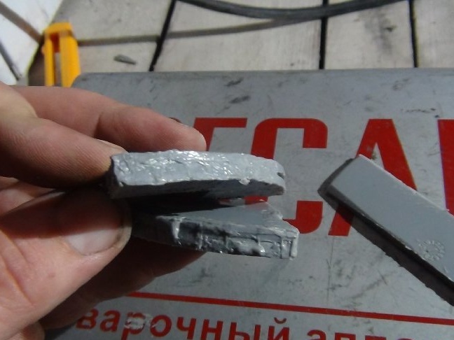
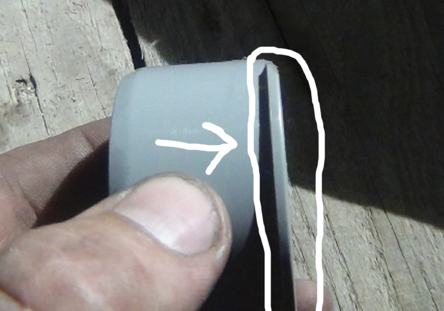
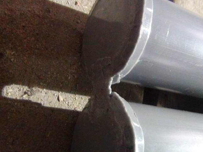
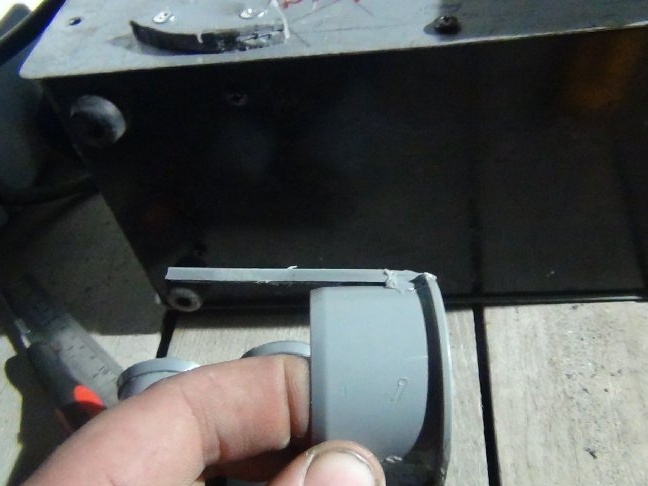
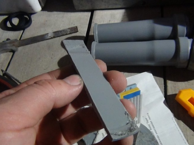
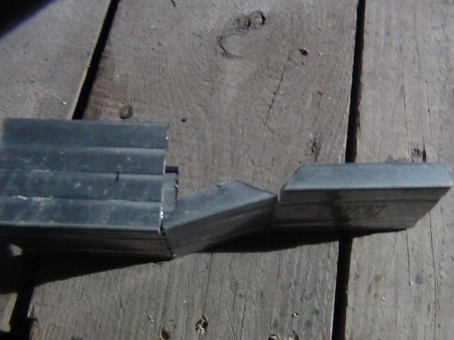
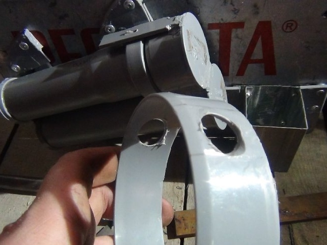
The trimmed edge is obtained at an angle of 90 degrees, it will rest against the mounts themselves, where the same cut. To avoid this, the grinder cut the chamfer (arbitrary angle).
As a result, this decision will facilitate the removal and reinstallation of the tube.
Zasov made of plates from the 110th stub. These bolt bars will be soldered to the tubes of the tube. Due to such locks, the tube will hold tightly to the welding casing.
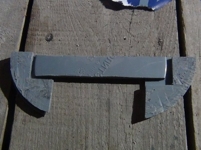
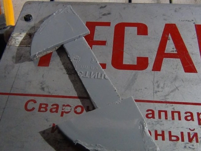
I cut the chamfers with the grinder as well as on the mounts themselves, in the process I tested this lock and made sure that the chamfers should be both on the mount and on the bolts.
As all the chamfers are made, you need to solder the trims to the tubes and you can start drilling holes for the rivets on the body itself.
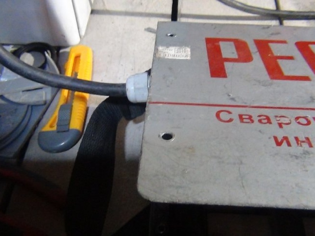
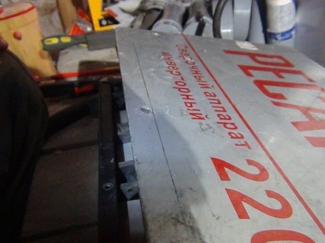
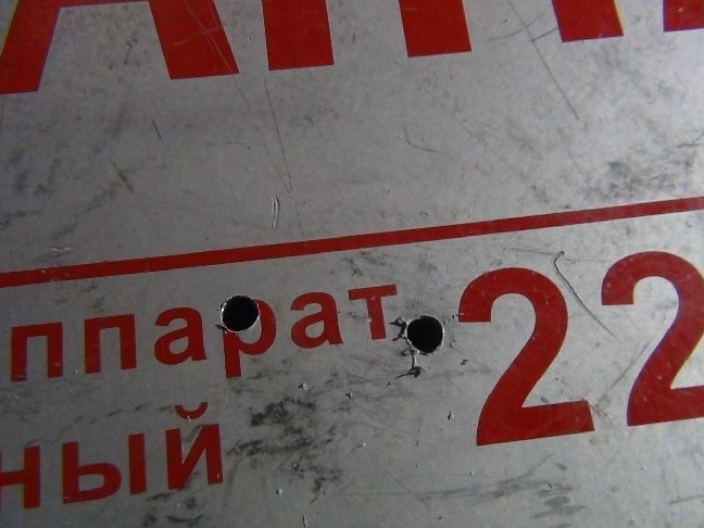
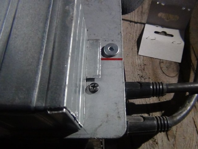
But not so simple! Before drilling, make sure that the installed rivets will not interfere with the installation of the casing back to the place on the main body where the inside of the device is located. The casing is fastened with ordinary screws to a metal frame. Missing this not unimportant moment, you will have to drill holes.
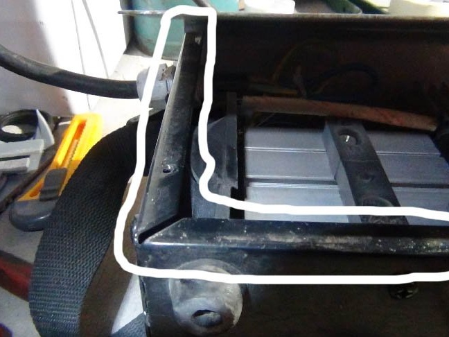
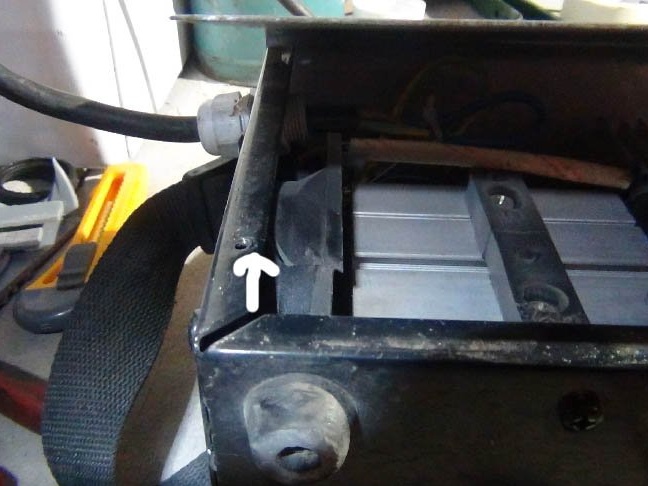
He measured 5 mm from the mounting holes in the center of the plane and drew a line bounding the edge for rivets with a pencil.
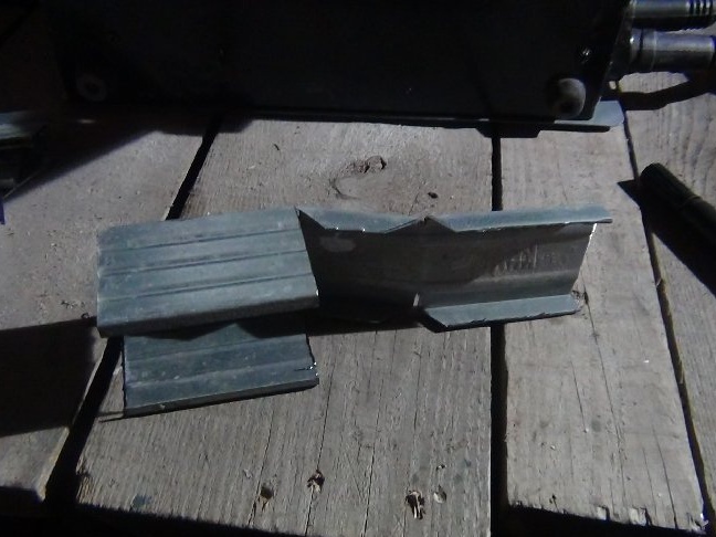
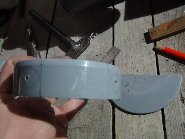
As all marked up, you can finish the deadbolts.
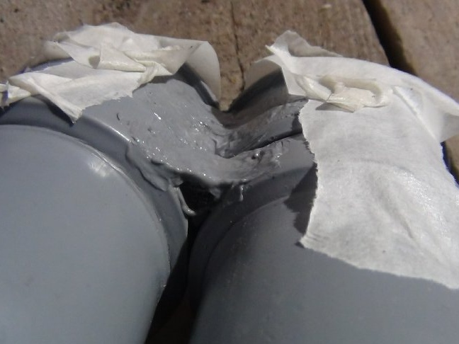
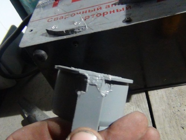
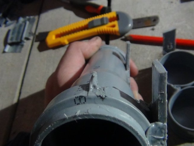
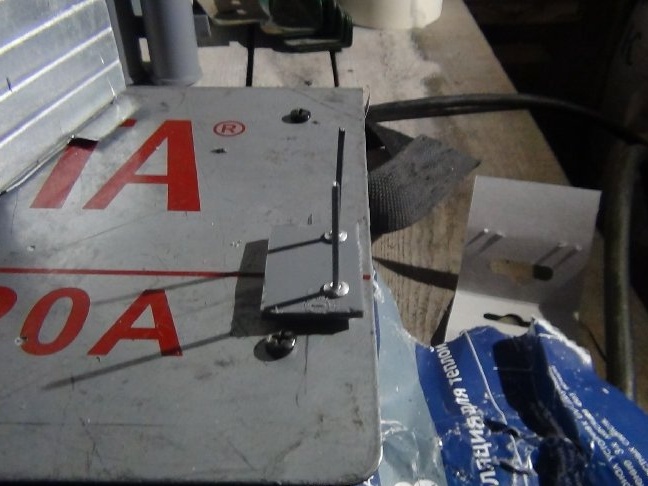
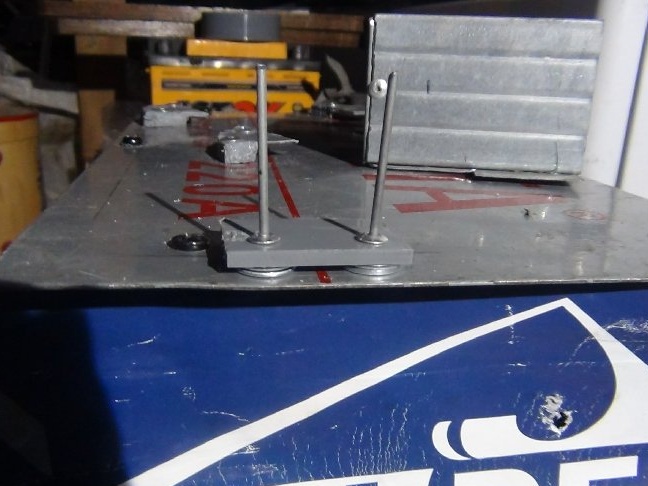
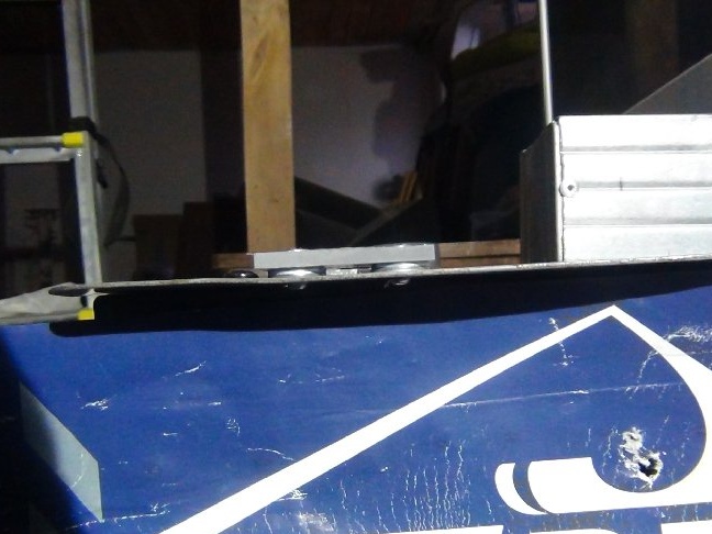
Preliminarily, having placed the fasteners and trims with the tube on the housing, he began to move from side to side all the details in order to determine the location. As soon as I decided on the situation on the tubes, I noted the places where the strips will be soldered. The tube is obtained at an angle relative to the bottom of the entire weld.
I soldered the bolts with a soldering station along the socket and at the bottom near the bottom with a rod and scraps from those scraps of the plug.
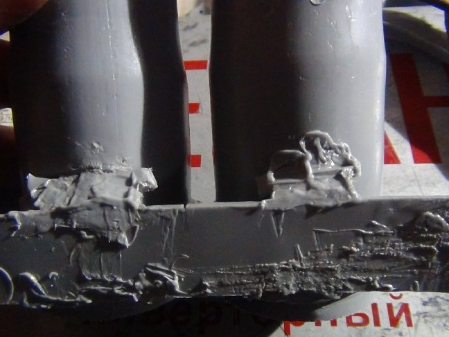
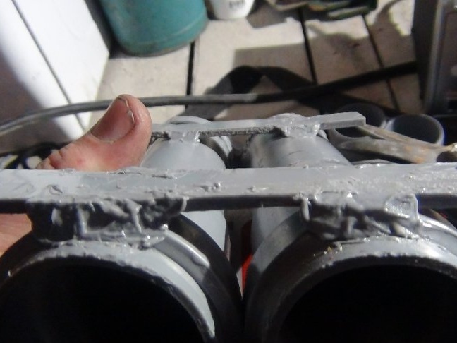
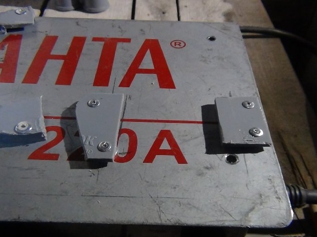
Before drilling, when the place has already been determined precisely, without marking with a marker, it made it easier, strongly pressed it with my hand to the body and drilled both the fasteners and the casing with a screwdriver. Set rivets 4x10 mm in thickness and length the most optimal.
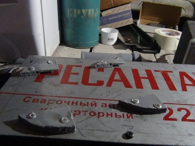
After completing this work, I tested it by lifting only the tube, nothing cracked, everything holds tight. You can not be afraid that if something may fall off in the process.
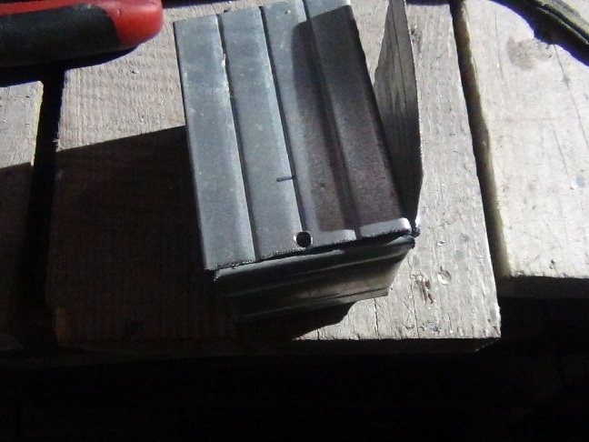
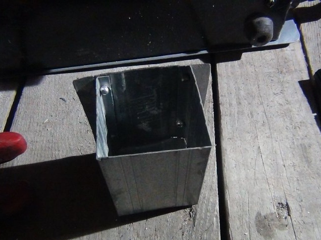
Step 4: Capacitance for electrode residues.
I decided to make a container for the remnants of the electrodes because of the small scraps that remain.
He worked at height, cooked bows in a metal temporary shed, and threw the rest under his feet. Going down the ladder for the next batch of electrodes, he stepped on such a slip, he poked the sole of my working berets and slightly injured my leg, not much, but the feeling was not pleasant.
He called this capacity an "ashtray", because the same small "cigarette butts" from the electrodes remain as from cigarettes, meaning you can’t imagine a better name.
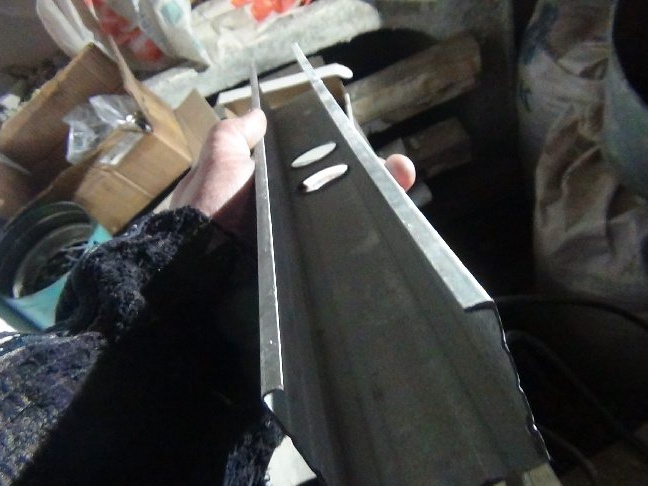
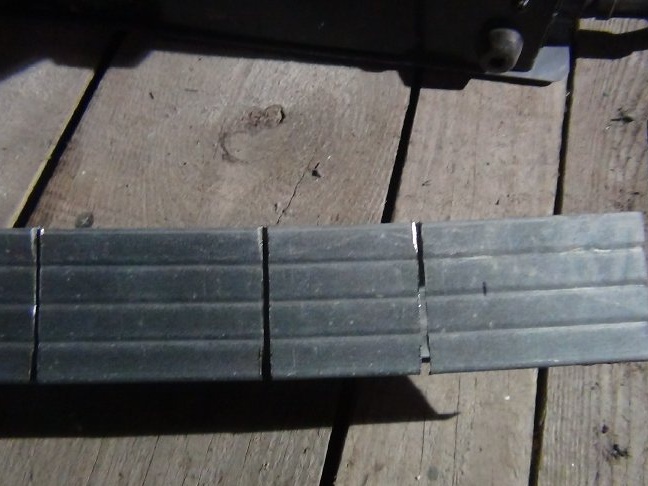
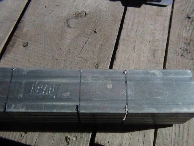
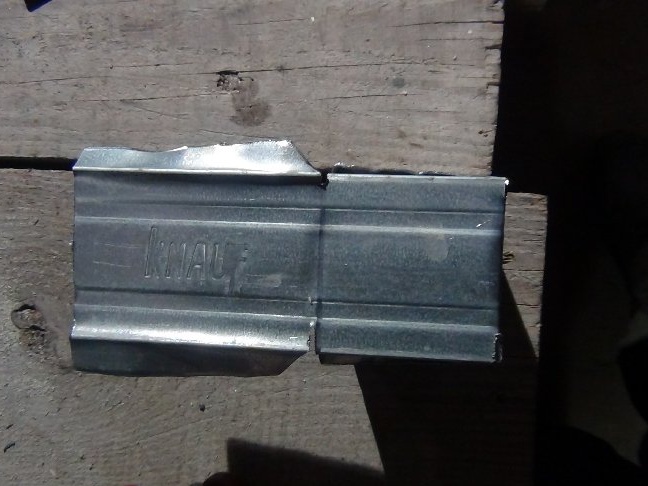
The farm has a lot of scraps from drywall profiles, I hand in scrap metal, and just in sight was a piece from the partition profile 50 mm by 50 mm. From it I decided to make.
The dimensions came out 7x5x5 cm, where 7 cm is the height.
The piece itself was about 50 cm long, and I needed only 17 cm.
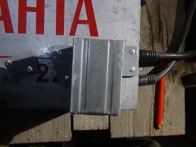
The box was the simplest. I cut off the excess and bent through the slots in the box, just like in origami.
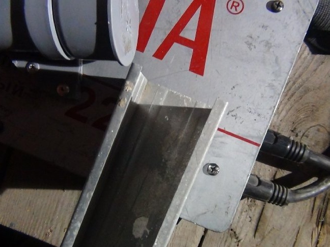
How to fix it on the welder, in fact, you already know the answer! Same as for the tube. I need these fastenings also not to be noticeable if the ashtray is removed as unnecessary.
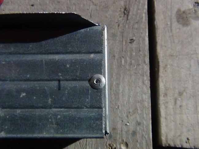
Parts of the profile were bent with a hammer on the anvil in one plane with the back of the back of the box, two ears formed, like a tube bar-bolt.
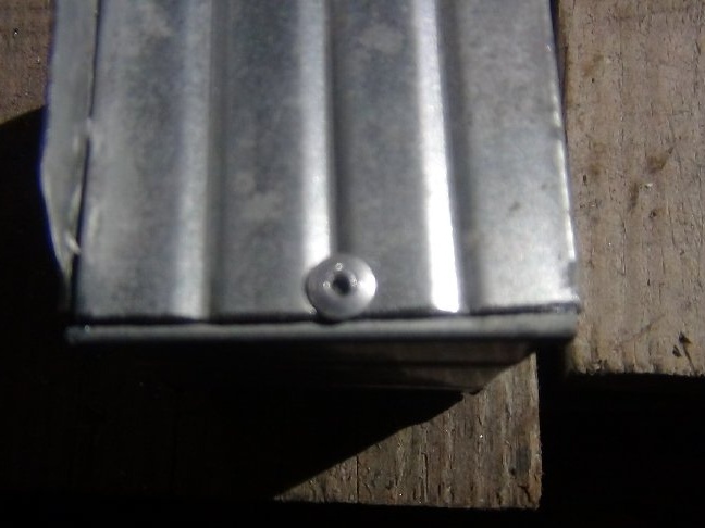
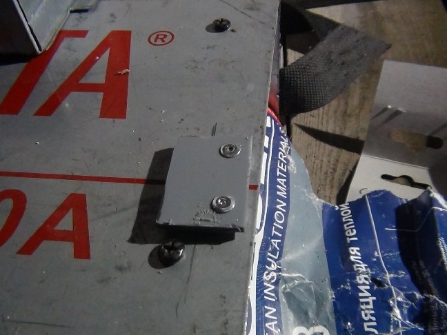
The box itself was mounted on rivets 3.2 by 6 mm.
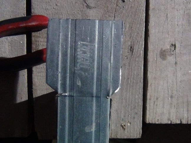
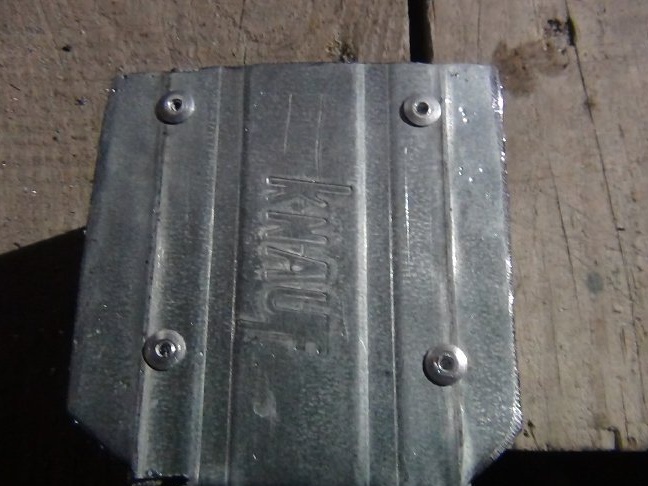
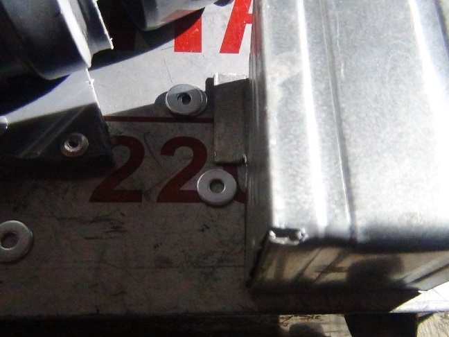
As I wrote above, this box will be under the tube, but the screw of the case prevented the installation of fasteners, so I had to cut the ears so that they abut the screw itself, the remnants of the electrodes do not weigh 10 kg, so that such ears will be normal, as they say.
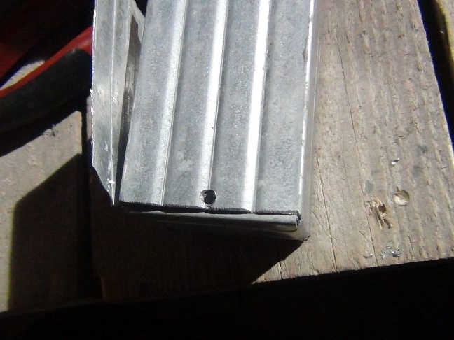
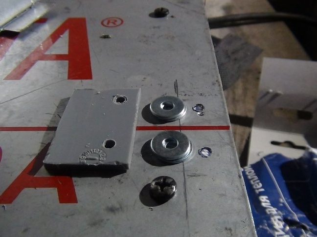
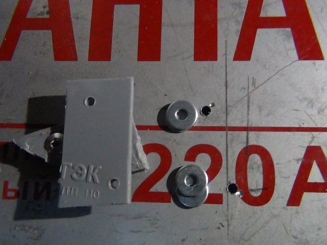
Here I decided to make the lower part not with plastic, but with two washers under one riveting.
He drilled as well as for the tube, pressing it tightly with his hand. Installed mounts on rivets 3.2x10 mm.
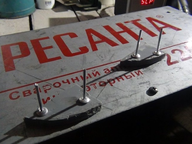
Step 5: Attachment for the hammer.
As he wrote at the beginning, the hammer (he certainly appeared later) and all sorts of objects that he used to beat off the slag were constantly lost and the places where they were lost were forgotten ...
I also decided to make a mount for the hammer, since I made it, and proved to be quite functional in business.
To make such a fastener as in the previous description did not make sense. Here I began to puzzle how and where to determine it ...
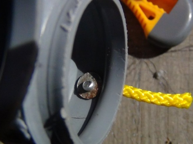
Many ideas flashed like a wind in my head and decided to make an unusual mount.
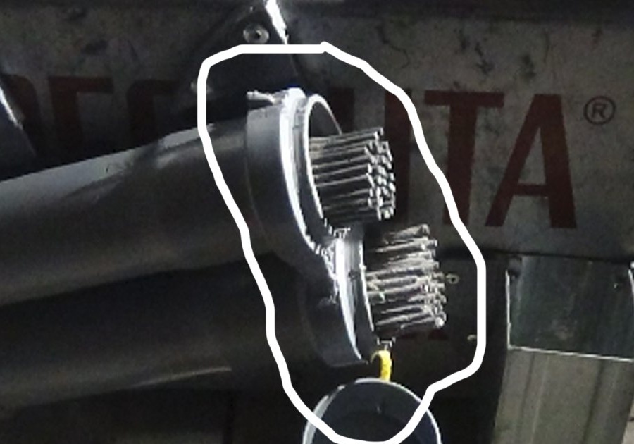
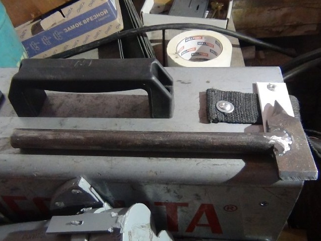
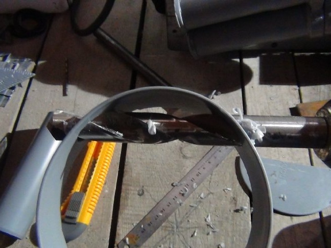
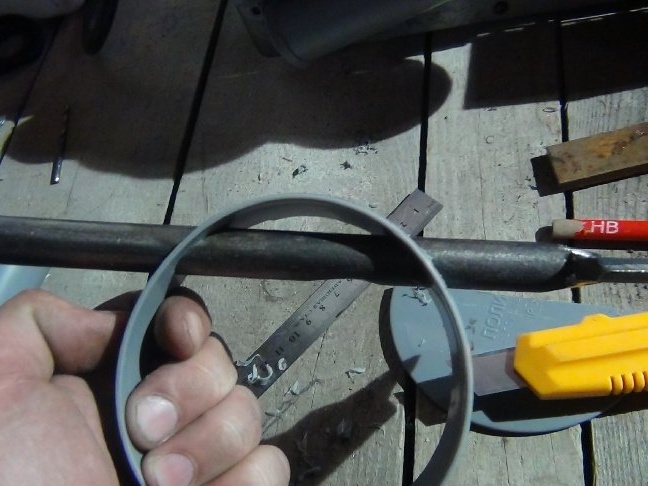
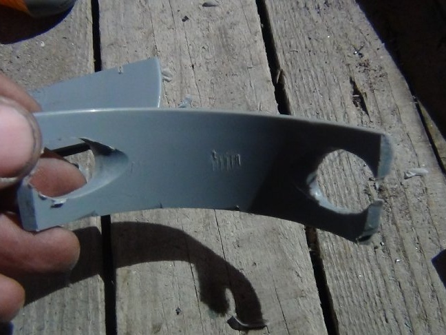
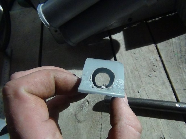
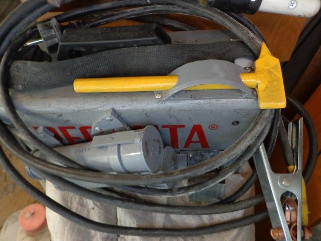
An unused ring from a large stub went into business.
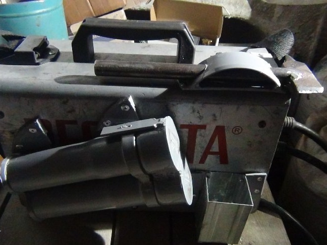
In the first photo you could already see this performance of the mount.
Further description.
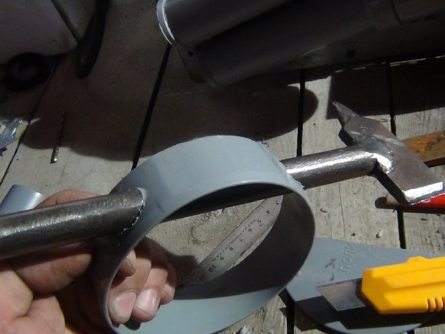
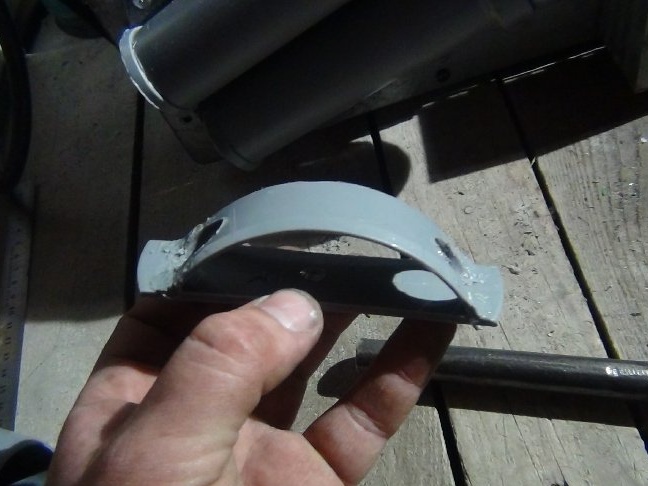
Twisting the rim in the hands and the hammer decided on this form (see photo).
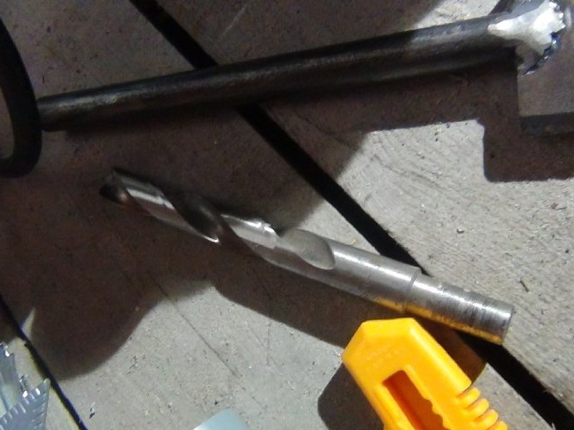
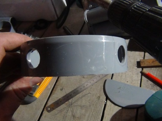
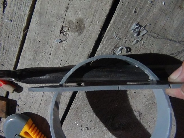
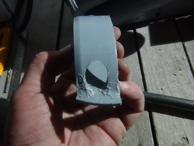
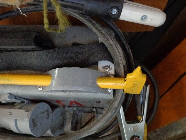
Since the hammer will not enter straight along the center, but as if along a displaced tangent, it is necessary to drill oval holes.
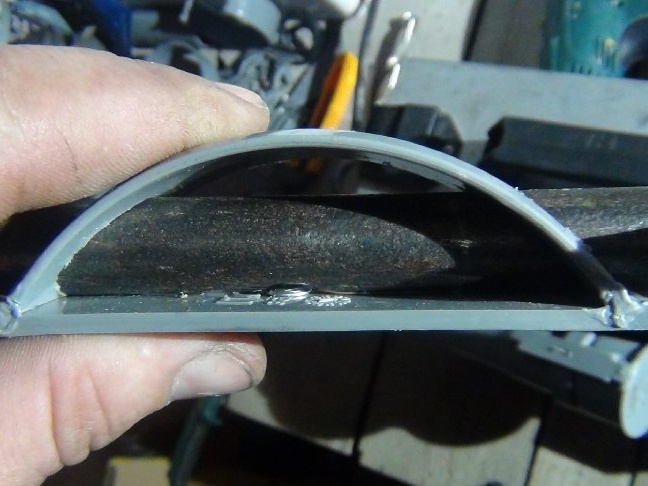
After determining the height of the arc relative to the site of the future fastening, I made marks where I will drill with a 4 mm metal drill and then with a 16 mm drill, the diameter of the hammer handle is made of 16 rods.
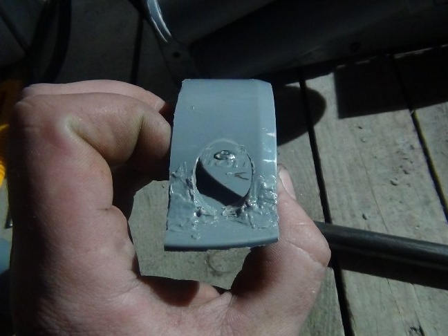
To get an oval hole, you first need to drill perpendicular to the circle, I get confused how to describe it correctly, and then turn to the side of another hole, as a result, the length of the drill made it possible to make a through hole, in the direction of the hammer's entrance and the plane of the plate we get an oval hole (see photo). Subsequently, this mount proved to be the best and did not have to come up with an additional hammer retainer so that it would not fall out.
The mounting plate for the last fastening was cut out from the remains of the stub; it just fit the width and the length, too.
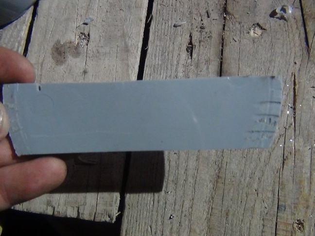
It remains to solder the arc to the plastic, then I almost used up the unnecessary plastic remains. There was no point in a soldering station, it made it an ordinary soldering iron.
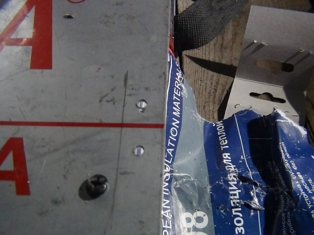
I determined the place for this fastening on welding from above, made a forward shift so that the belt being on the shoulder in a tense position does not interfere with getting out the hammer.
Riveted on rivets 3.2 by 10 mm.
The drilling process as well as in previous cases, strongly pressed and drilled.
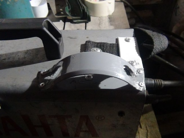
From the same hammer, here already savvy, it turned out not a bad hook for carrying a helmet (see photo).
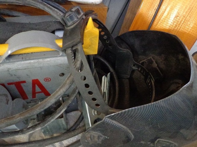
When you head to the place of work, your hands are free for material or something else ...

If you have questions, please contact, I will answer :)