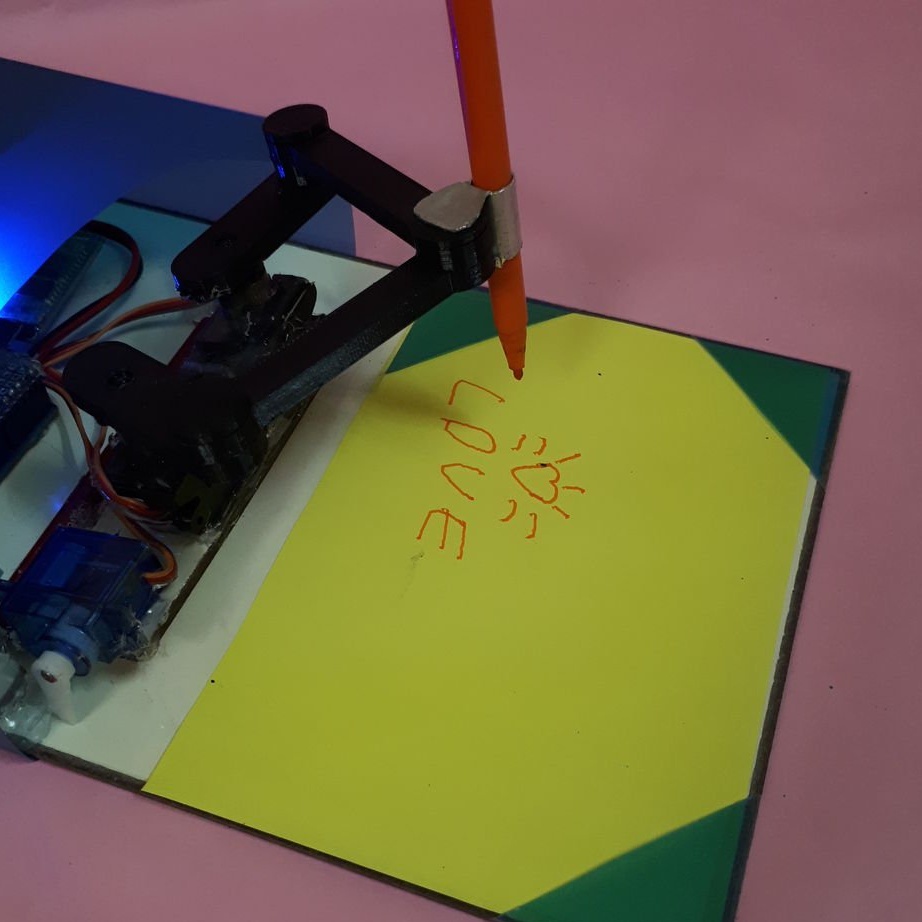

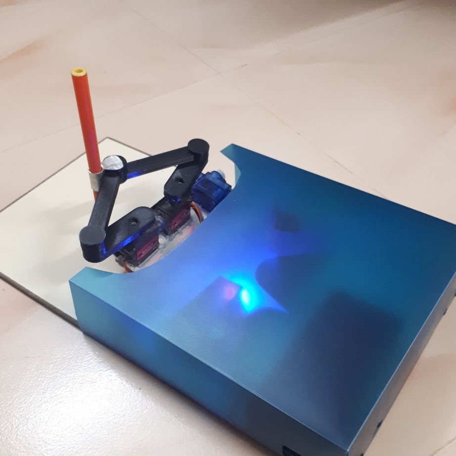
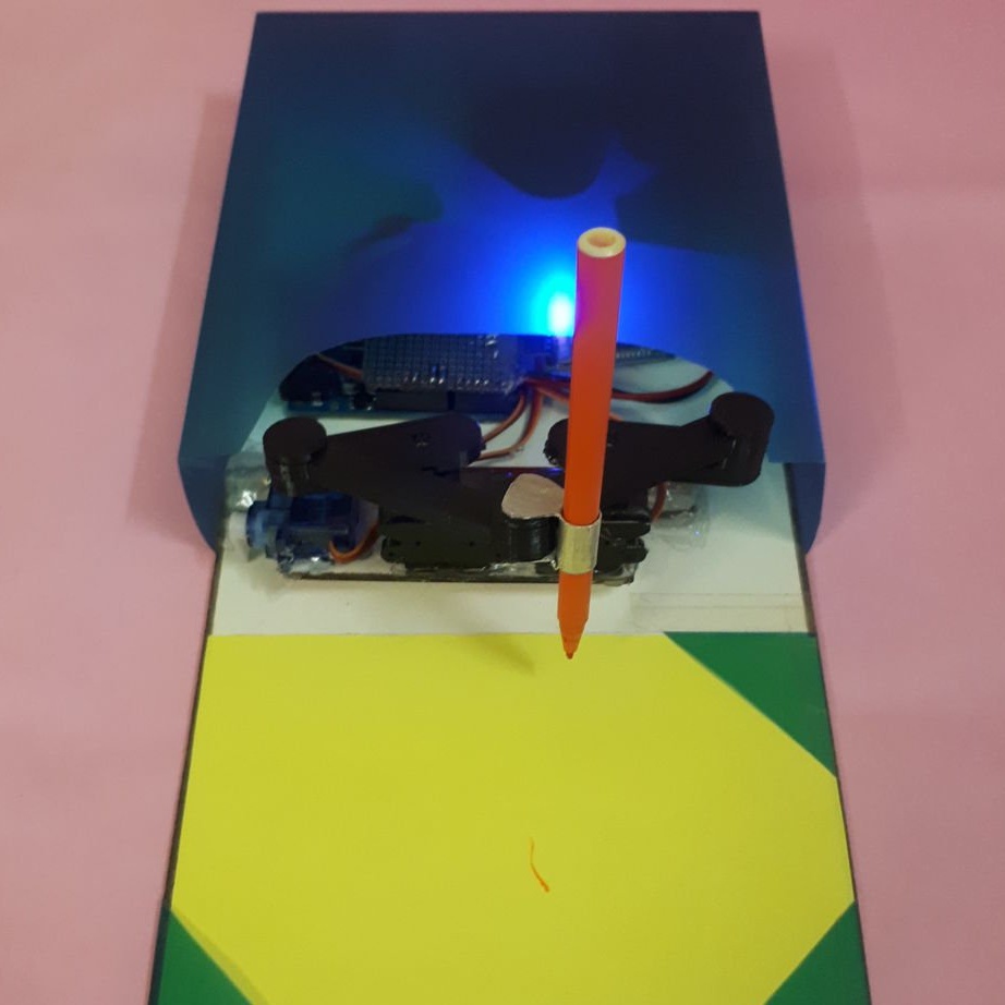
In this article we will meet an interesting homemade - a device that draws and writes text in real time, controlled via any Android device.
Let's see a short video with an example of how the device works.
Tools and materials:
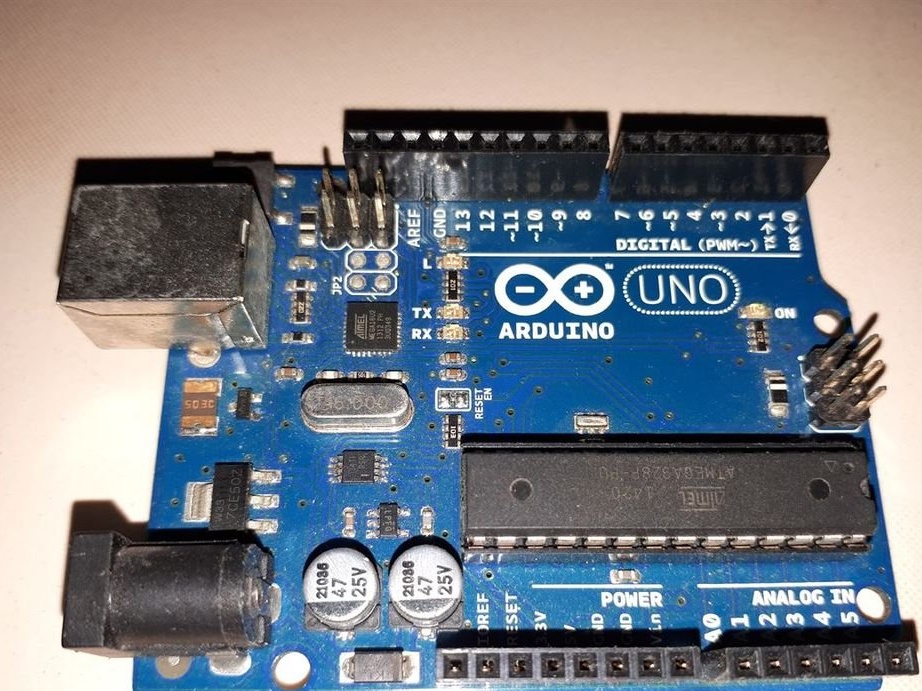
-Arduino Uno R3;
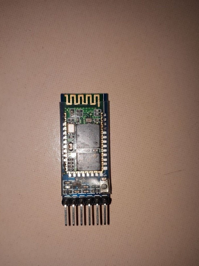
- Bluetooth module HC-05;
- Servo drive MG90S - 2 pcs;
Servo SG90;
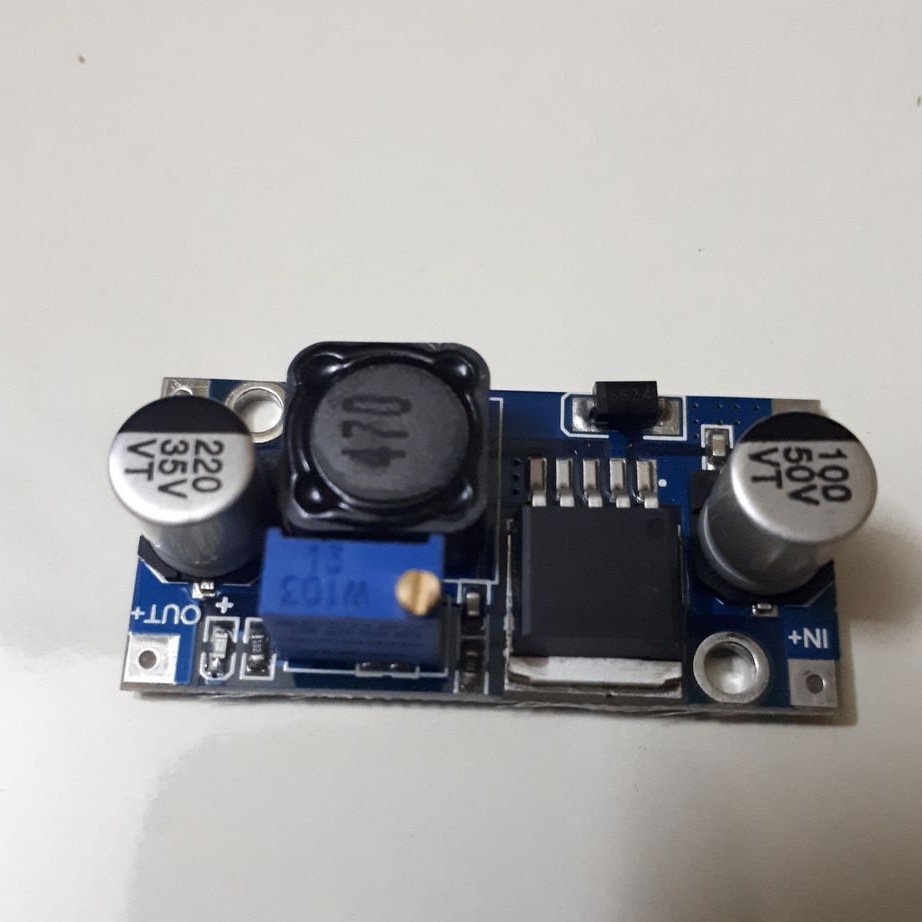
- DC voltage regulator LM2596;
-3.7V 18650 Battery - 2 pcs;
- 18650 battery holder;
- Small aluminum pipe (from the old FM antenna);
-Acrylic;
-Fasteners;
-Soldering equipment;
-3D printer;
-Ball pen;
-Smartphone;
Step One: Some Design Steps
In this step, the wizard explains with an example how to calculate the dimensions of the drives and the installation locations of the servos.
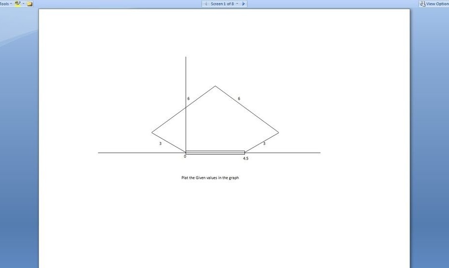
Image 1.
The size of the lower arm is 3 cm, the upper arm is 6 cm. The distance between the two levers of the servo is 4.5 cm. So, we will consider all this on the graph and mark the first servo center as 0.0, the second 4.5.0.
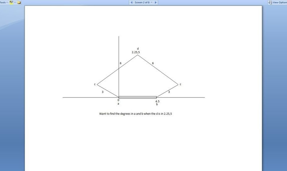
Image 2.
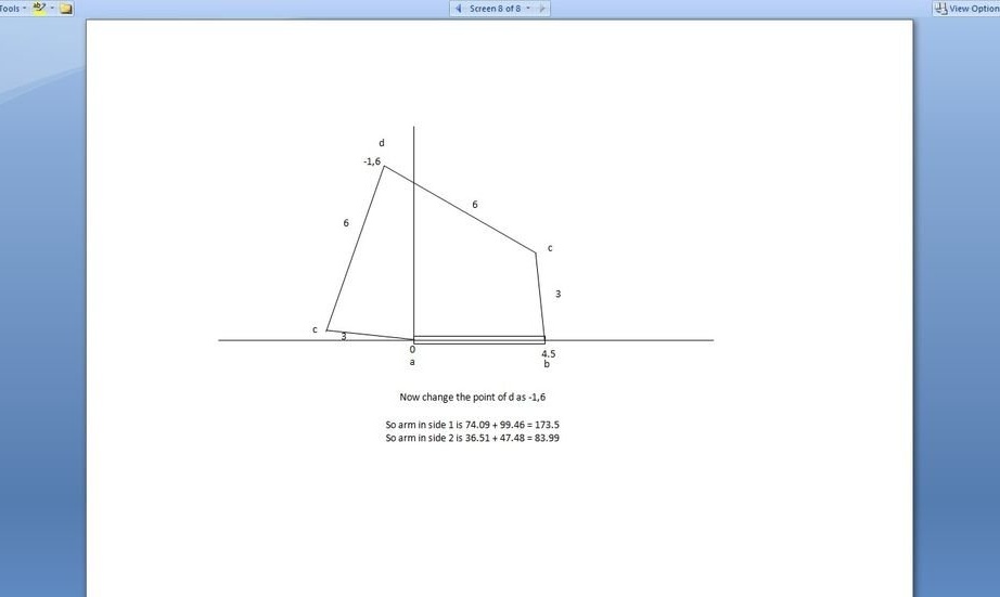
Now mark the point on the graph where the rod needs to be moved 2.25.5.
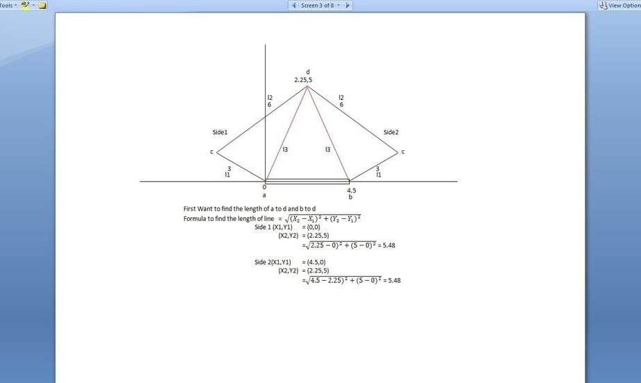
Image 3.
Now you need to find the length of the two lines (0,0) - (2,25,5) and (4,5,0) - (2,25,5). Use the distance formula and the Pythagorean theorem. From the formula Length = sqrt ((X2-X1) square + (Y2-Y1) square) (see Image to see the formula in the correct format). The point is located in the center of the Y axis with a servo drive, so both sides have the same triangle size. Thus, the result is 5.48 in both directions.
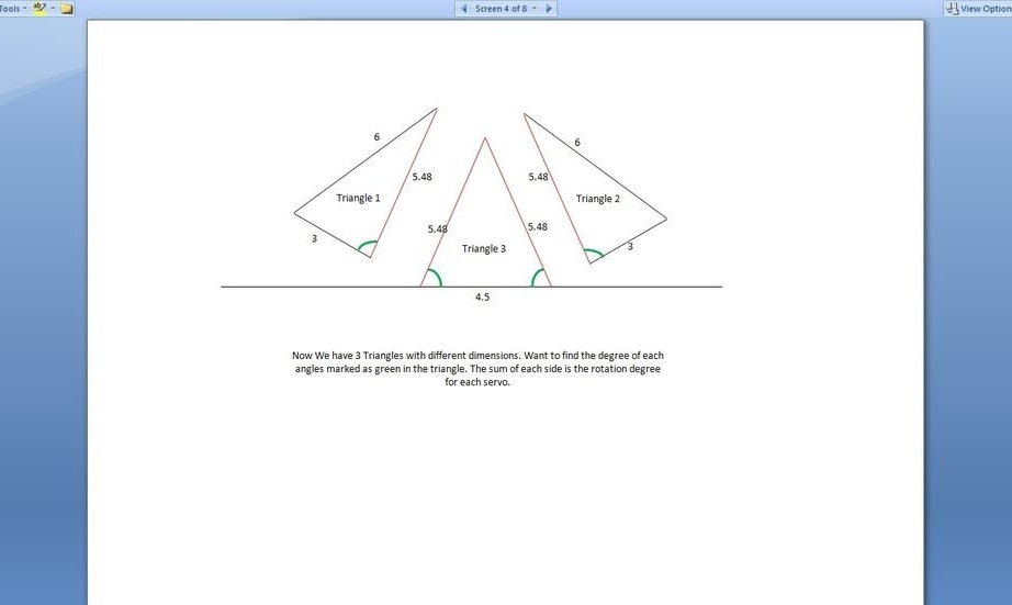
Image 4.
Now you need to separate the triangles. We got 3 triangles with all known 3 sides.
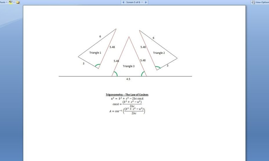
Image 5.
Use trigonometry - the law of cosines to calculate the angles we need.
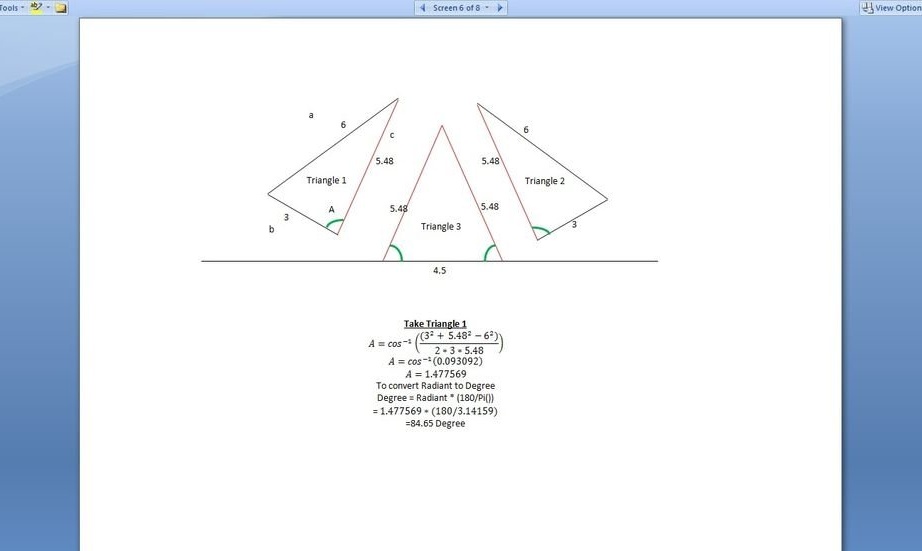
Image 6.
The result of trigonometry is expressed in radiant, so use the formula Degree = Radiant * (180 / pi
()) to convert the radiant to degrees.
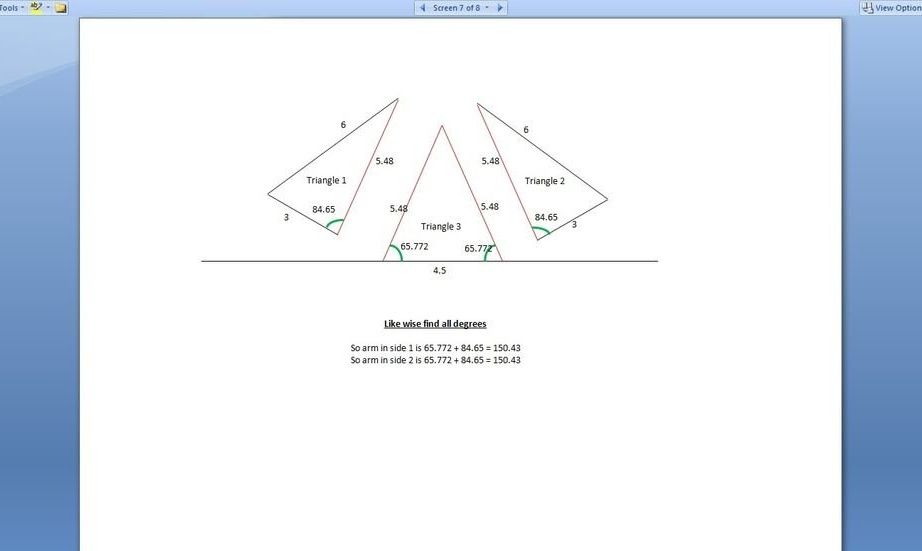
Image 7.
Sum the degrees on each side to the degree of movement of the levers.
In Excel, the wizard validates the calculations.
Calculation of hands.xlsx
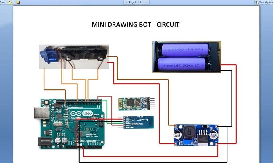
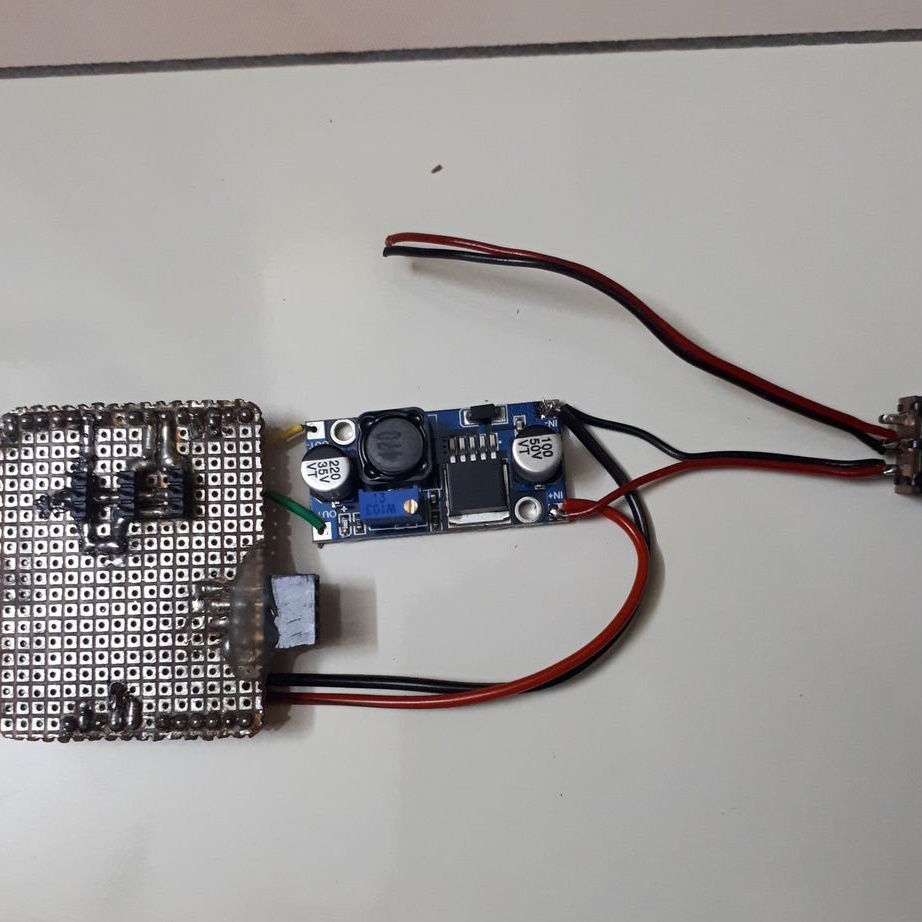
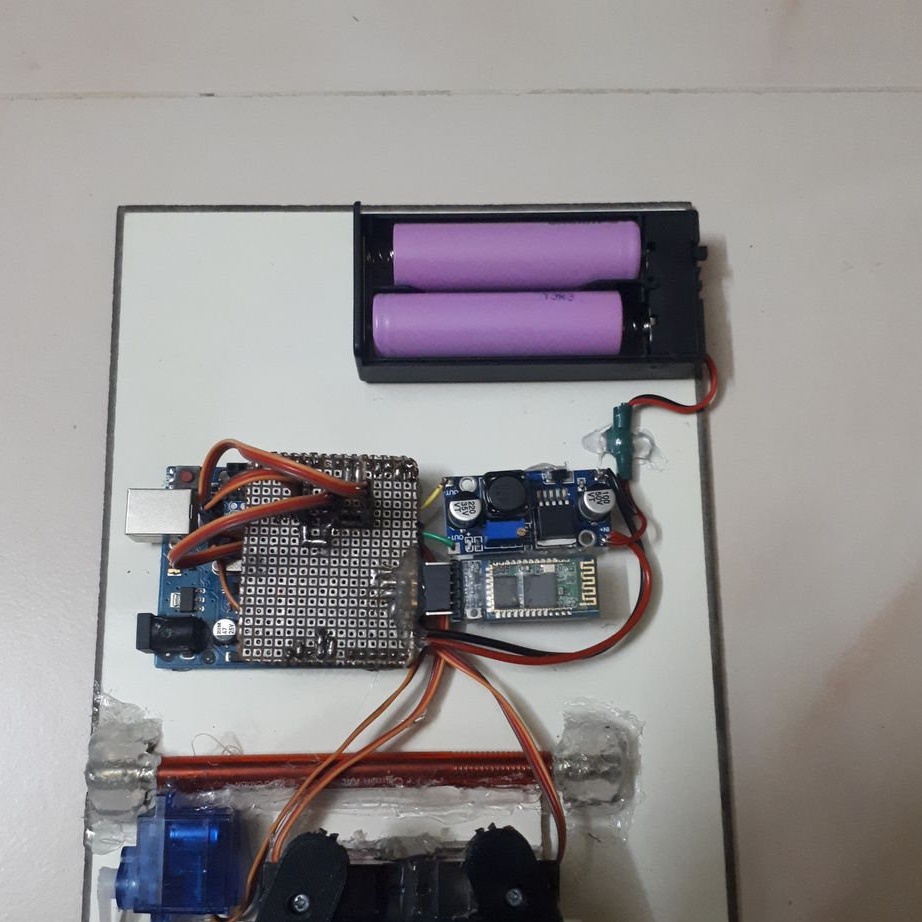
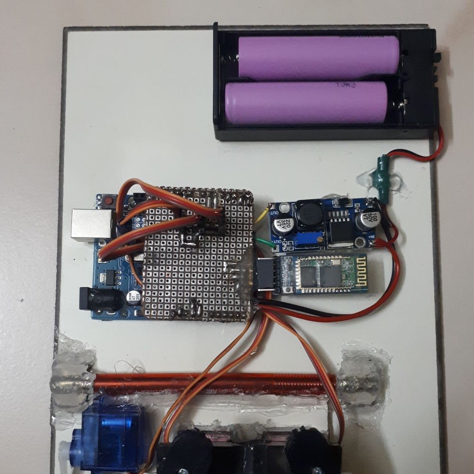
Step Two: Scheme
This is a very simple circuit with three servos. Connection via digital outputs 5.6 and 9, where 5 and 6 are used to control the lever, and 6 for lifting. The HC05 Bluetooth module is connected via Tx to the Arduino 0 (RX) pin, and RX is connected to the Arduino 1 (TX) pin. Power supply, 7.4 V, from 2 x 18650 batteries, is supplied to the Arduino's Vin-contact and, through the LM2596 DC voltage regulator, to servos.
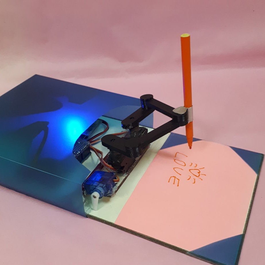
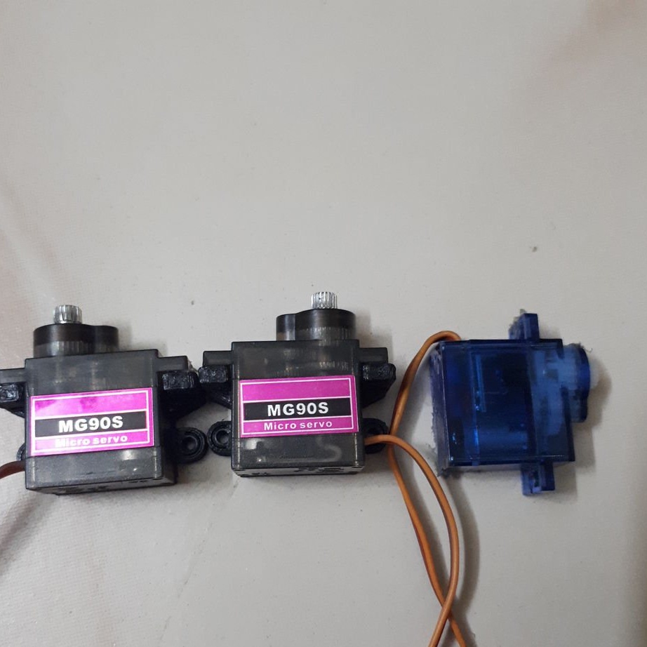
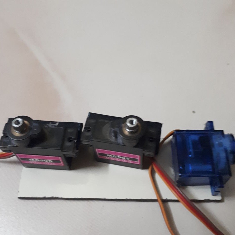
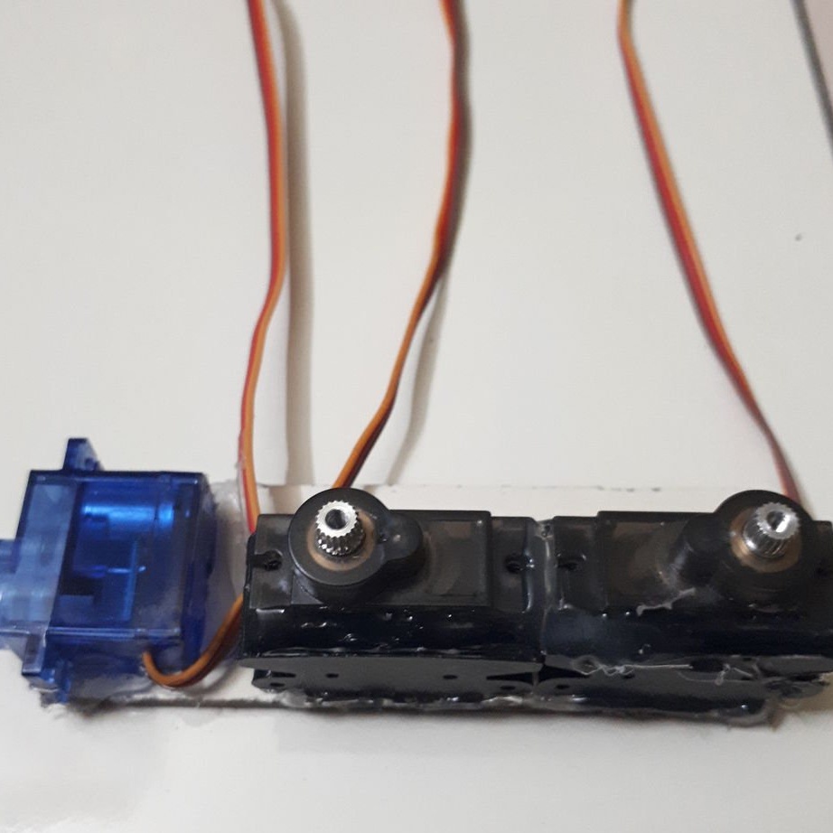
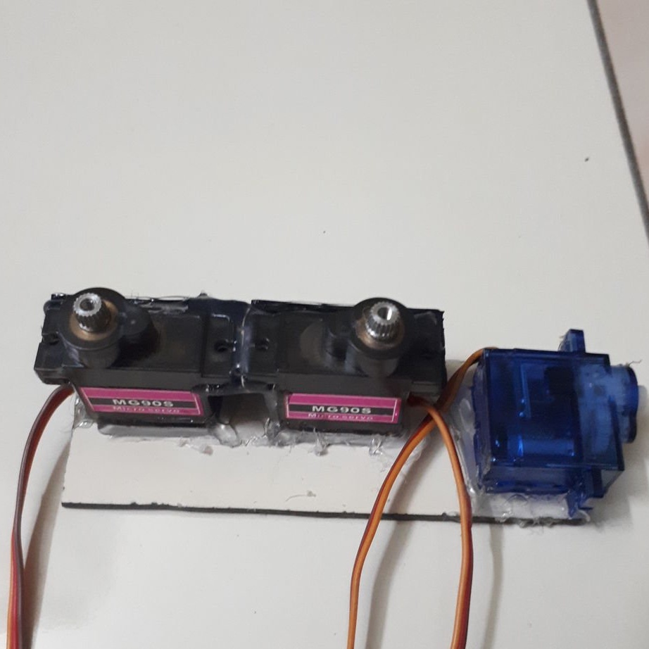
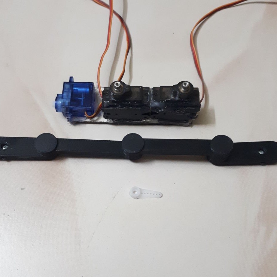
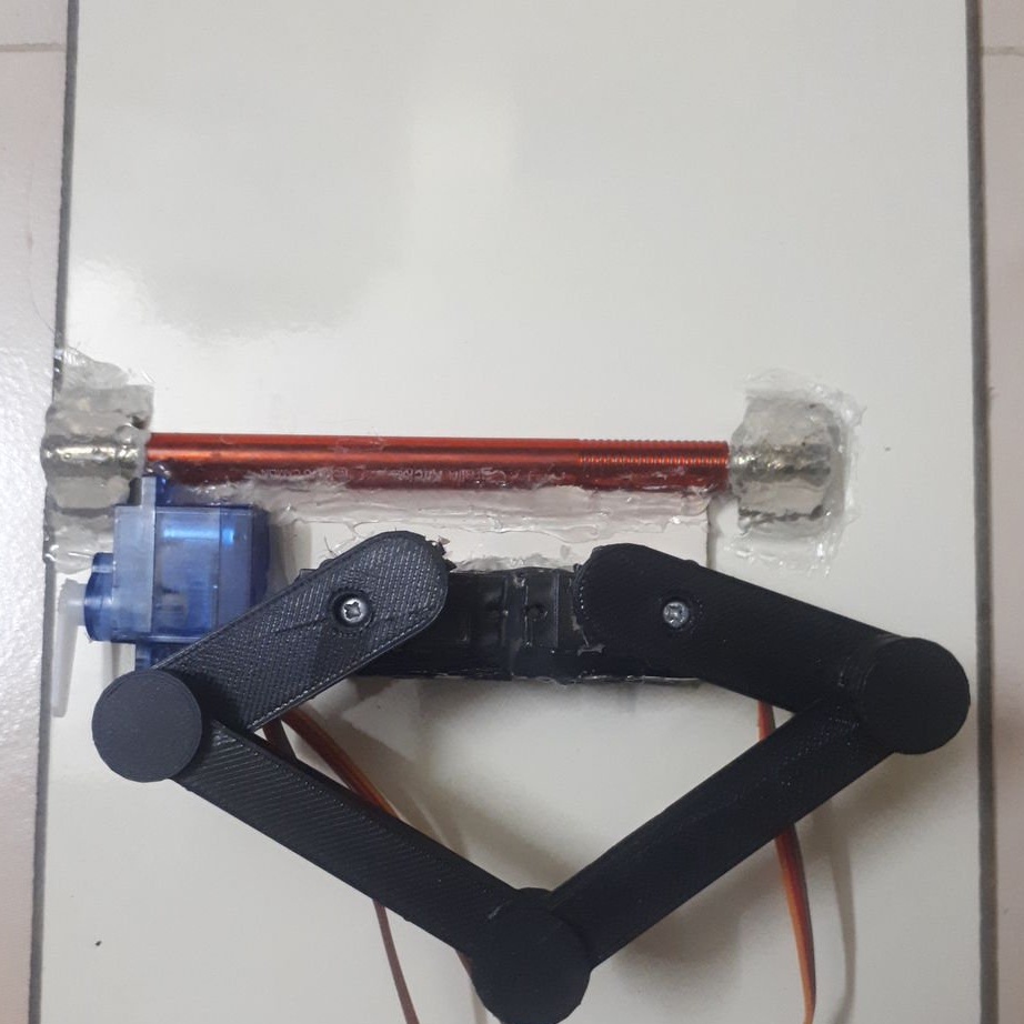
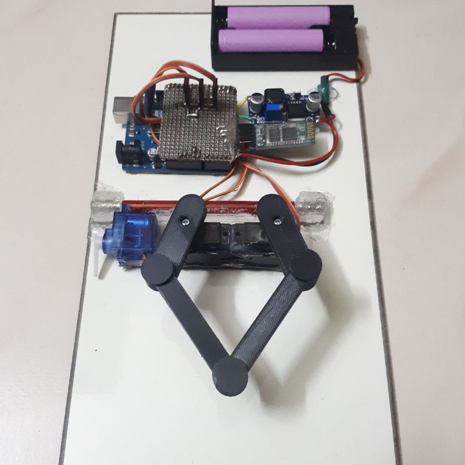
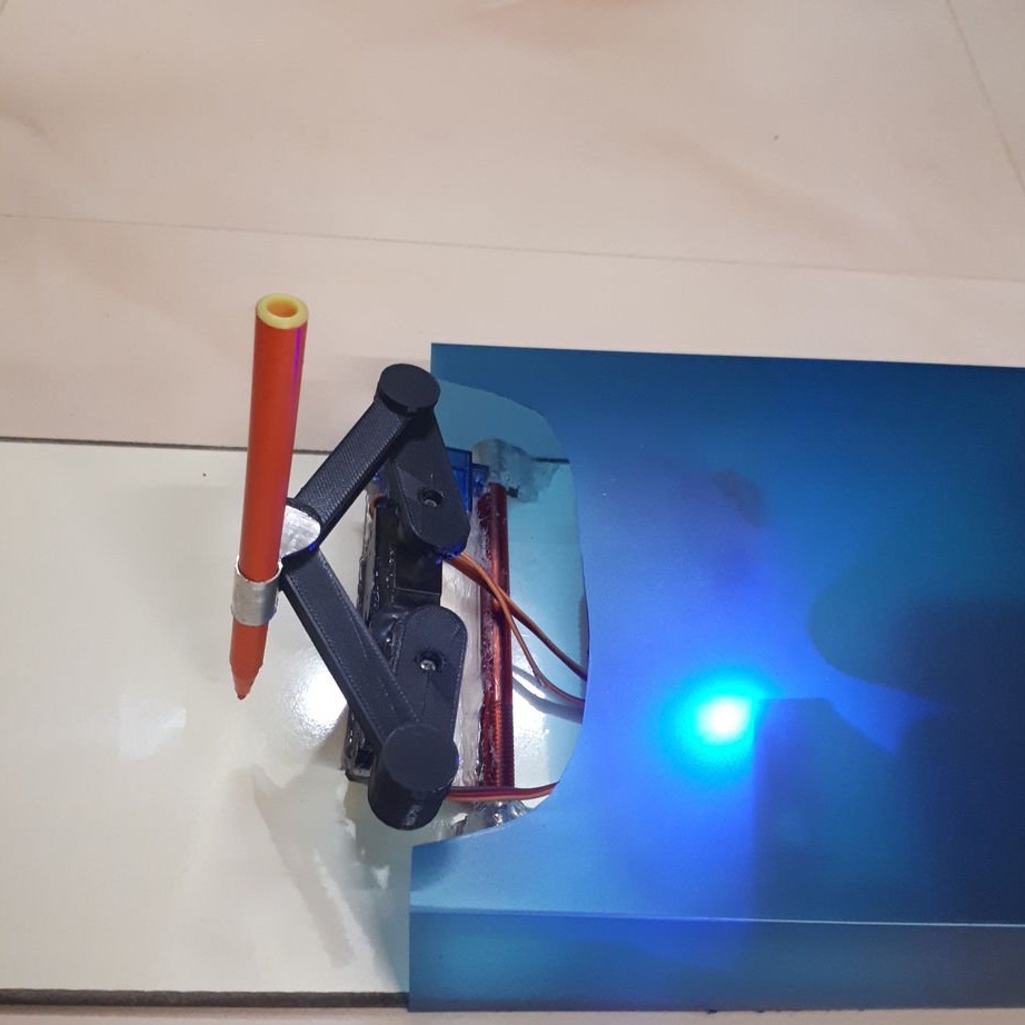
Step Three: Servos
The master uses two MG90S for horizontal arm and SG90 for vertical.Servo drives are attached to the acrylic sheet as shown in the photo.
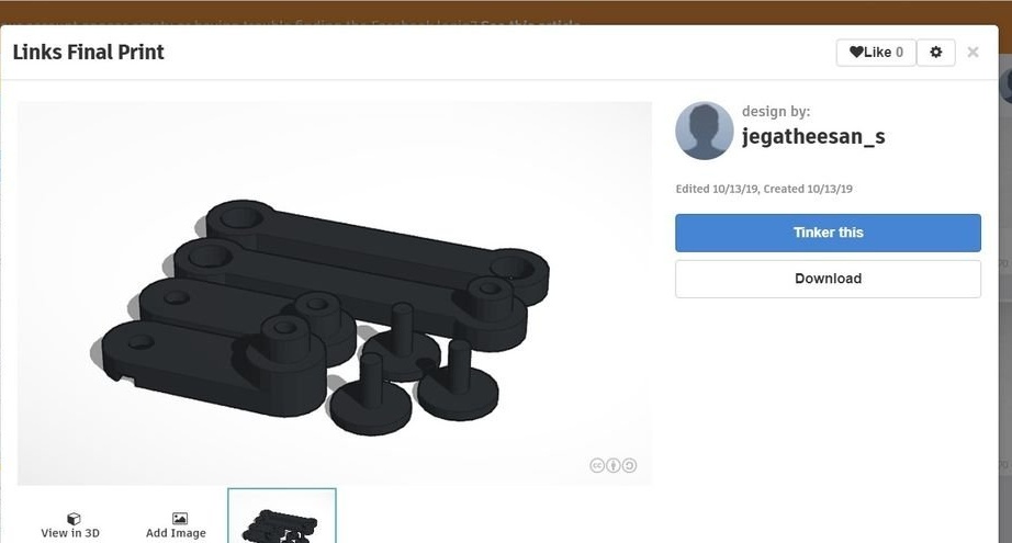
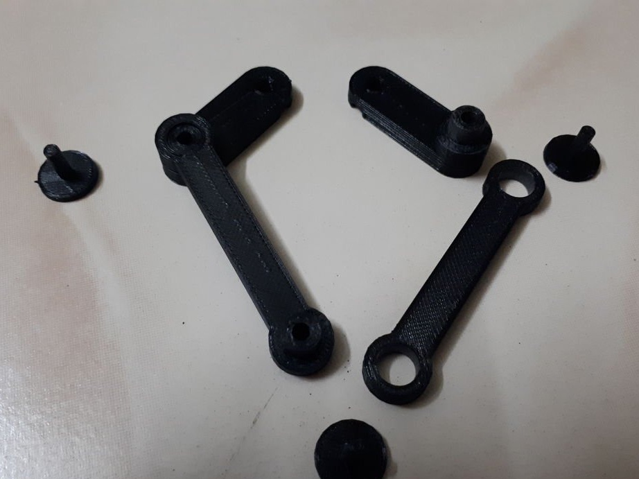
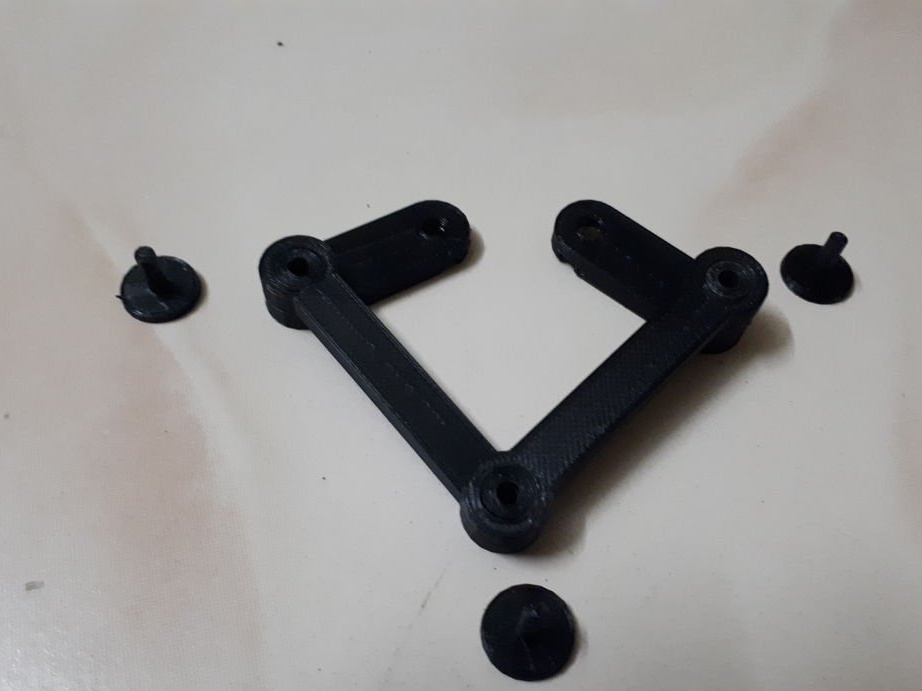
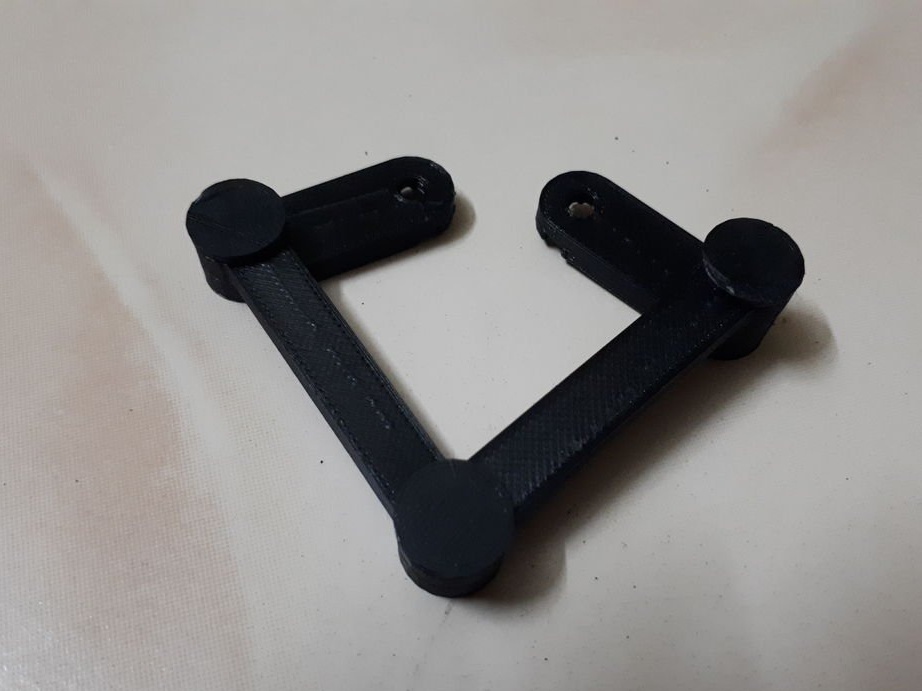
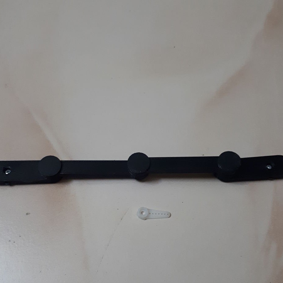
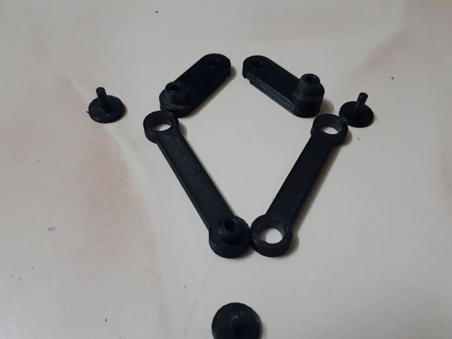
Step Four: 3D Printing
You can print the lever by downloading the files below.
Leglinks.obj
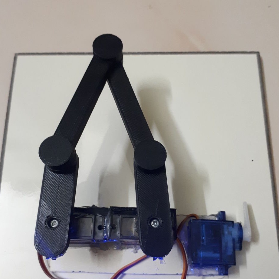
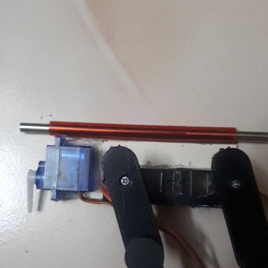
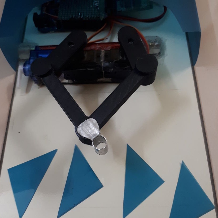
Step Five: Installing the Horizontal Arm
Next, the master mounts a horizontal lever on the servos.
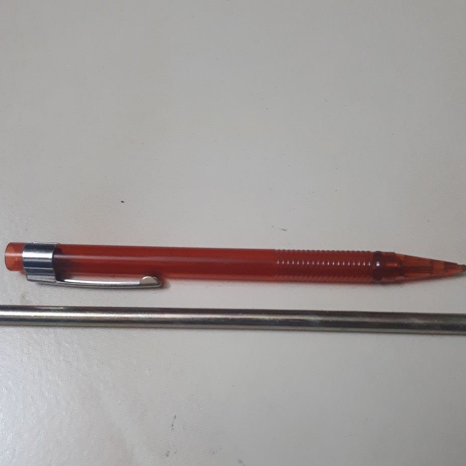
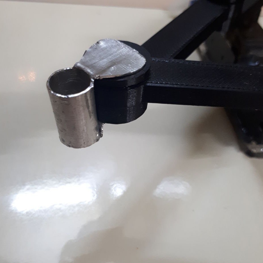
Step Six: Loop
The loop is made of a ballpoint pen housing and a metal tube. The housing is fixed to the base of the servos (acrylic with fixed servos). A tube is installed in the housing. The ends of the tube are fixed to the acrylic sheet (the base of the entire device). When a signal is applied to the servo drive, its lever abuts against the base, and the platform with the drives rises.
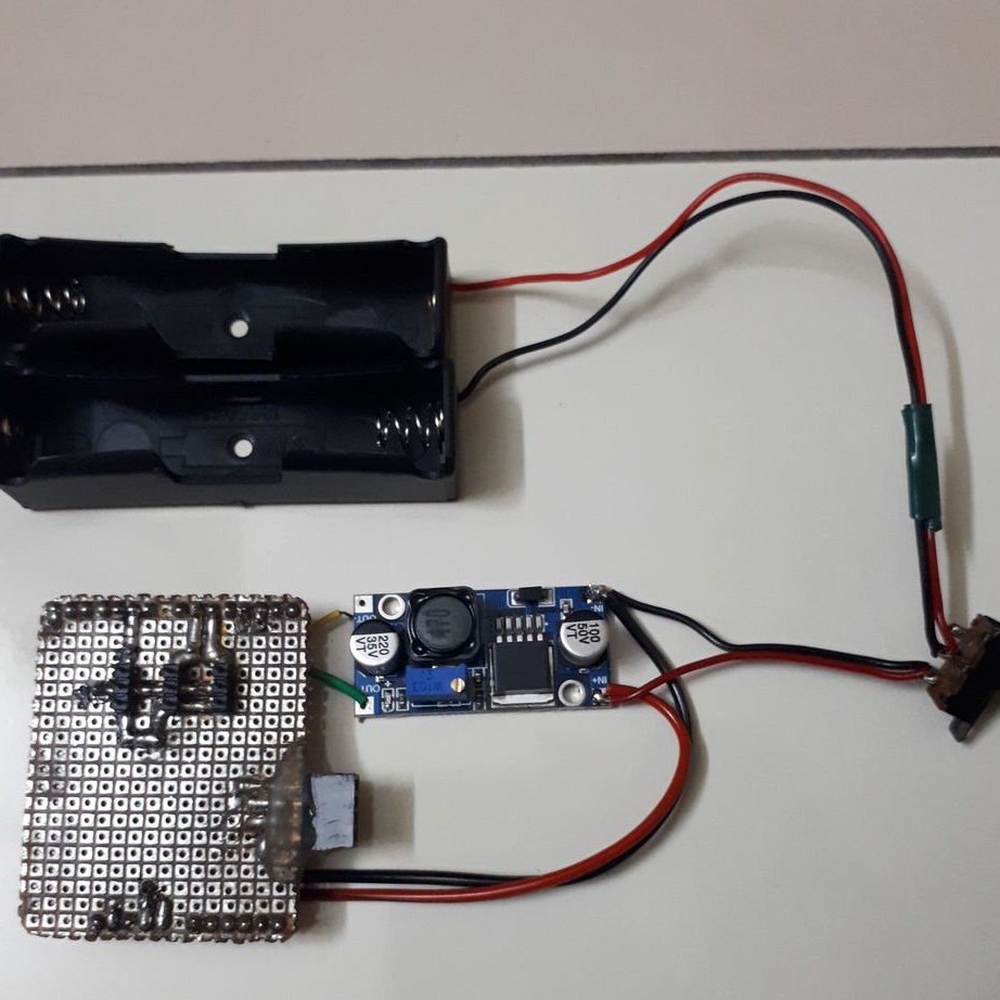
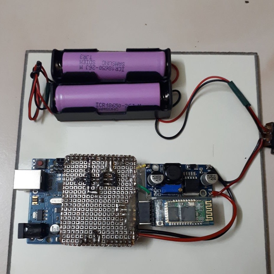
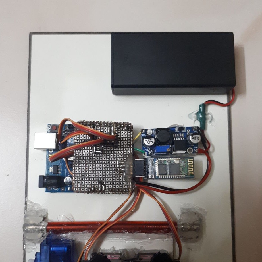
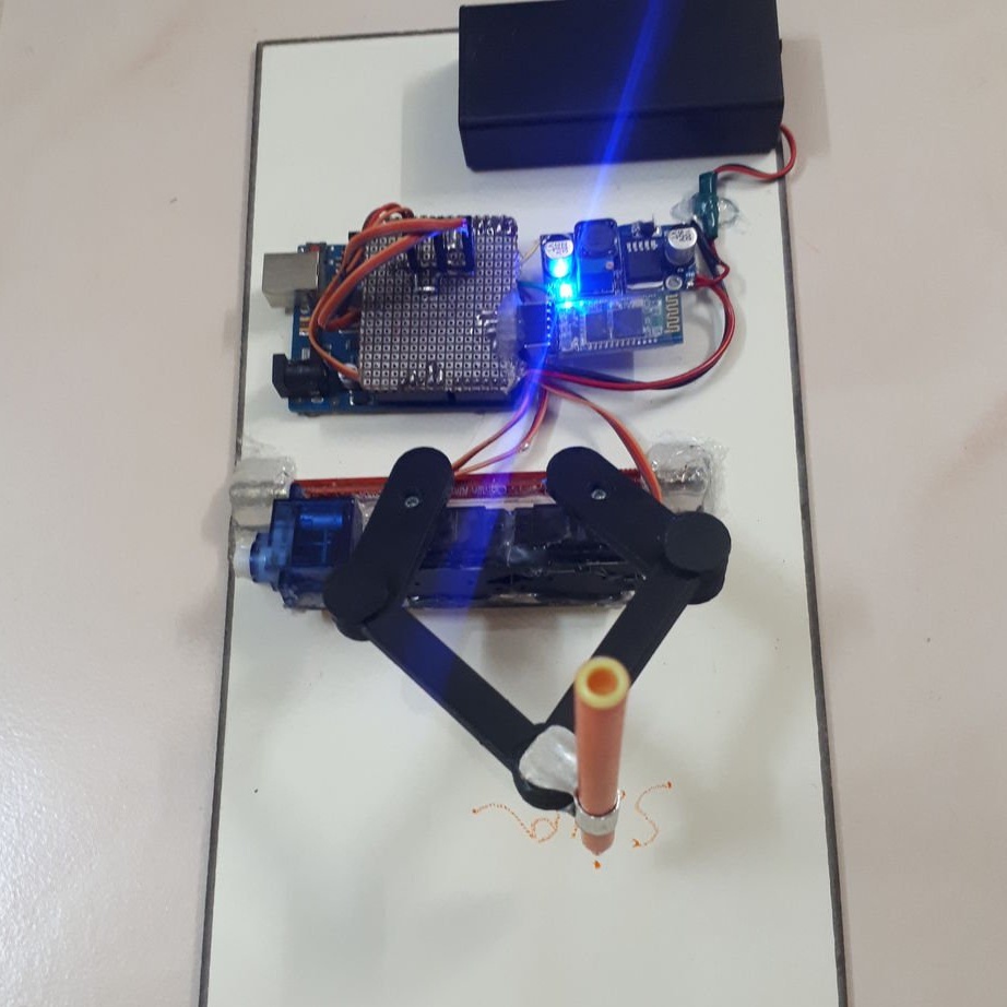
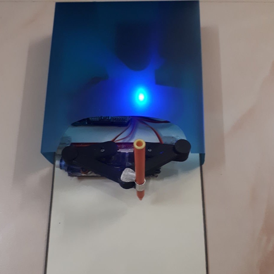
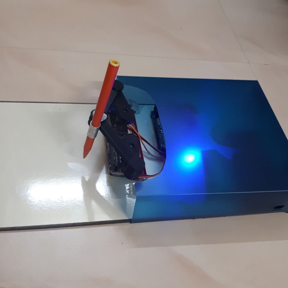
Seventh step: assembly
On the base, hot-melt adhesive, secures all modules and the battery compartment.

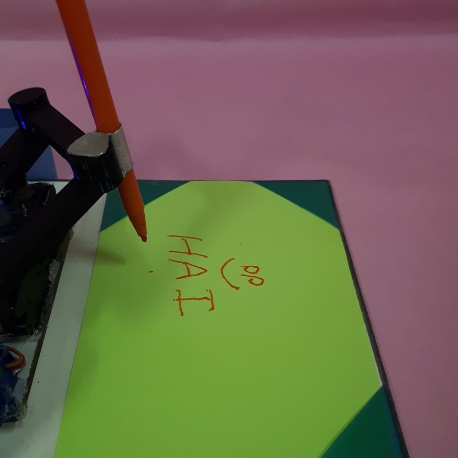
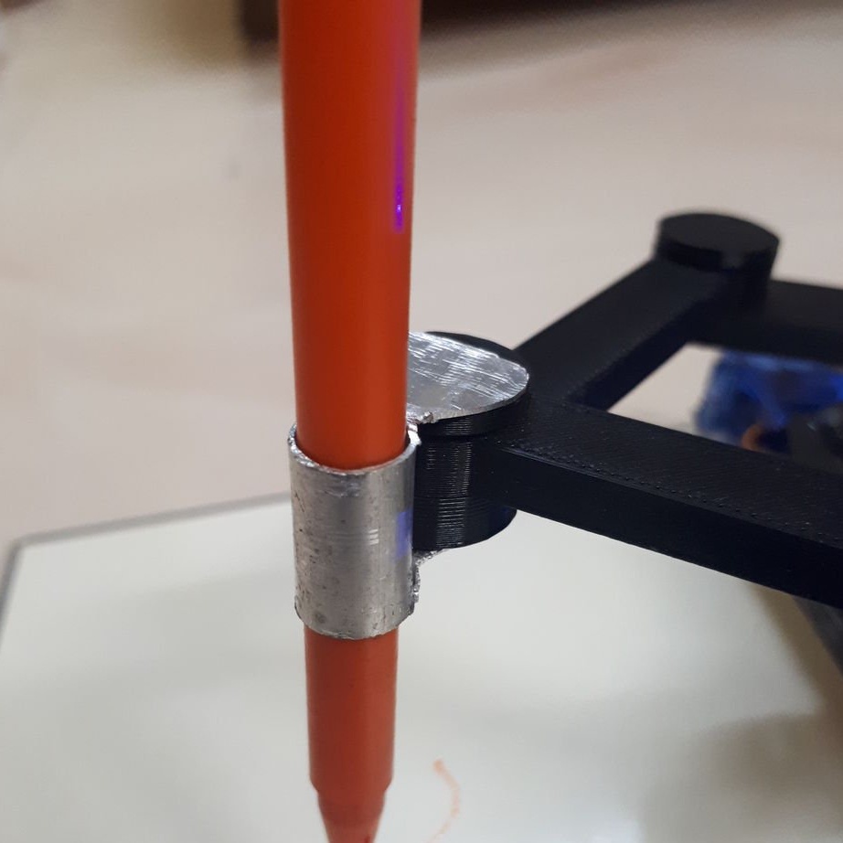
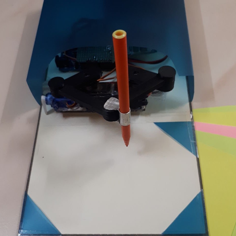
Step Eight: Pen Holder
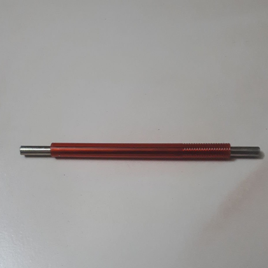
Now you need to make a pen holder. The master cuts off 43 cm of aluminum tube. 15 centimeters recedes from both ends of the tube and cuts into the radius of the tube. Then cuts these segments along and turns the ends of the tubes.
Crops and grinds edges.
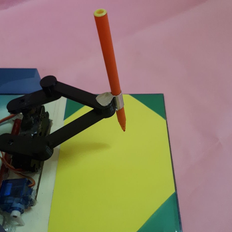
Secures the holder to the lever, installs a handle in the holder.
Step Nine: The Case
The acrylic makes the case of the device.
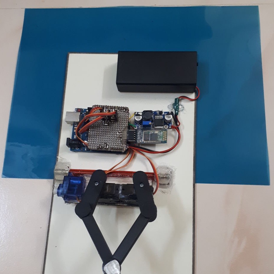
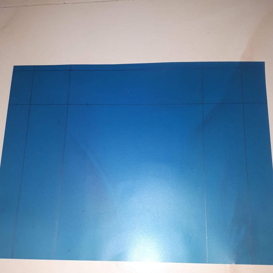

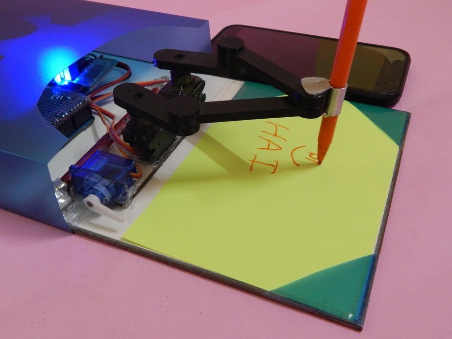
Step Ten: Paper Holder
Cut three triangles from acrylic. Secures them in the corners of the base in front of the lever.

Step Eleven: Code
Android sends a command to Arduino via the bluetooth module. Servos rotates 180 degrees horizontally and 60 degrees vertically. If the angle is larger, the lever rises up and freezes at the top point.

The code can be downloaded below.
Arduino.rar mini-drawing
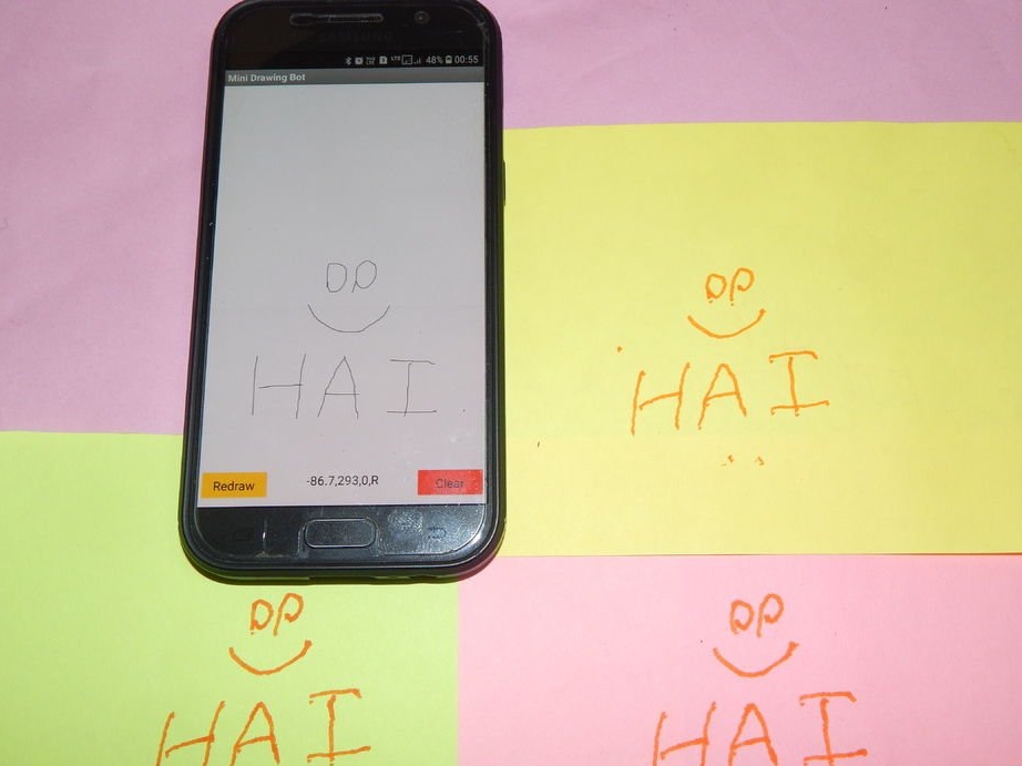
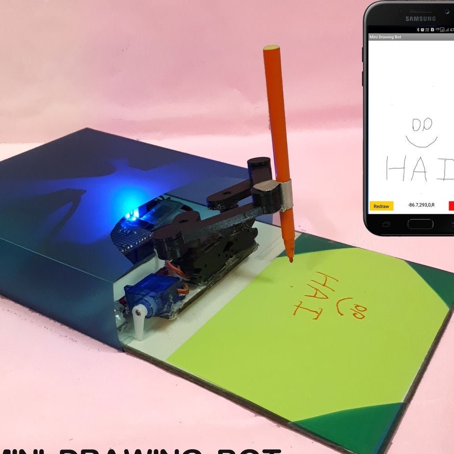
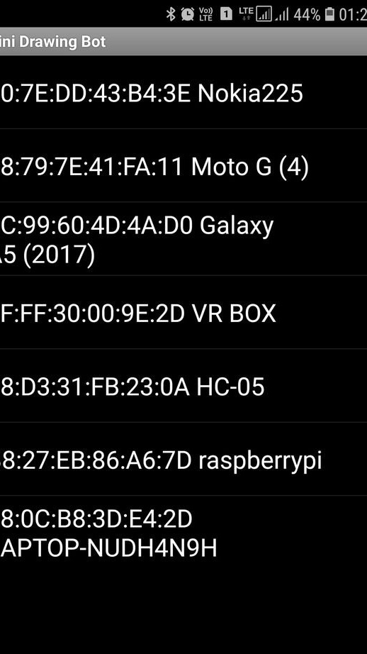
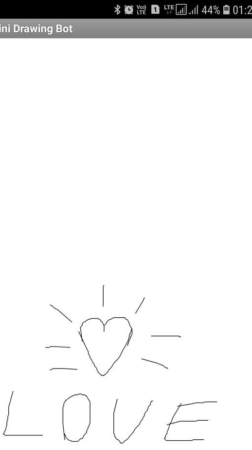
Step Twelve: Android Application
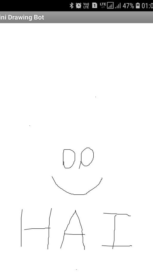
To control the device with Android gadgets, the master develops a special application. Pair the smartphone with Arduino and launch the program. The program has a window for drawing. All characters written on the screen will be reproduced by the device. At the bottom of the screen there are two control buttons and a shortcut showing the command. Due to the length of the lever you need to write at the bottom of the screen.


The program, in two versions, for users and developers, can be downloaded below.
Mini-drawing aia file.rar
Minidrawing apk file.rar
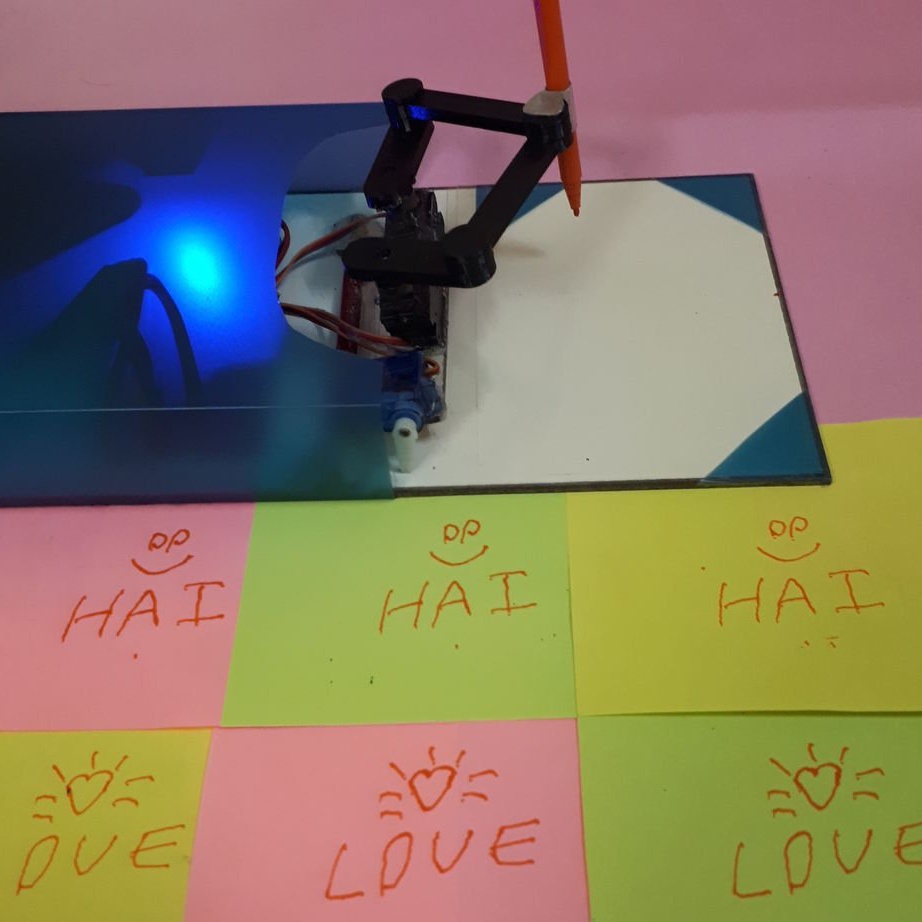
Then the wizard performs a test of the device.
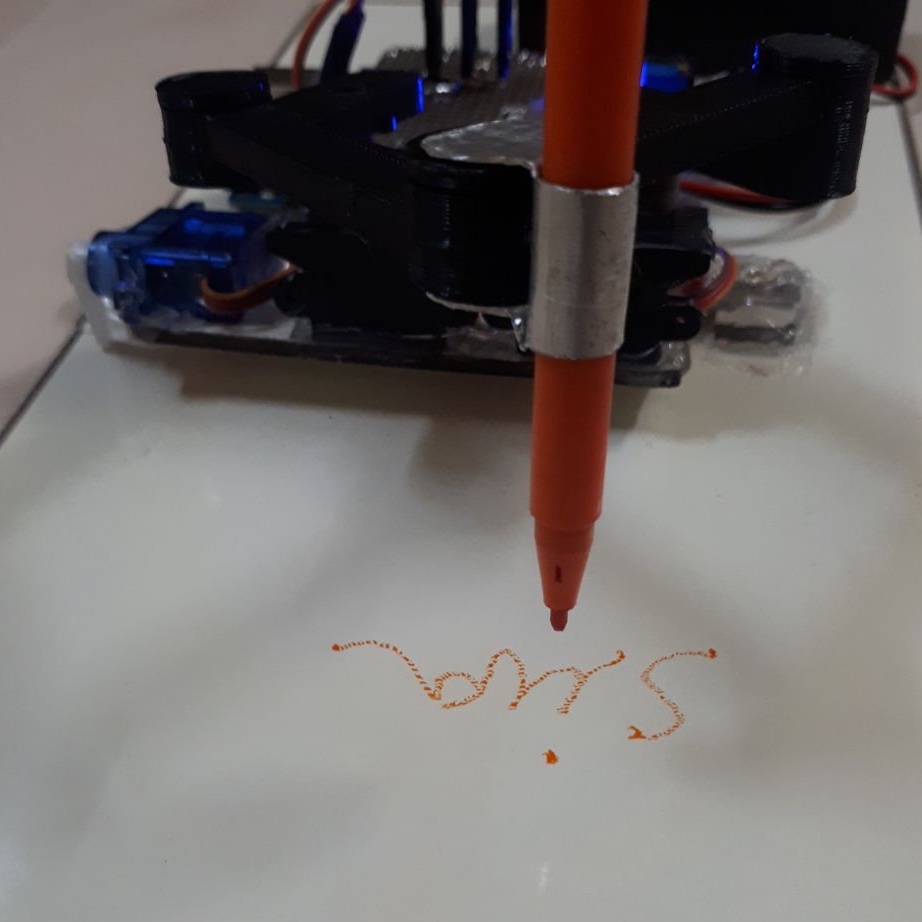
All is ready.