Greetings to all readers and amateurs to do do it yourself something useful (or not very) and beautiful (how to get it). I have long wanted to make myself a personal cache. Hide something valuable there or put aside for the purchase of a robot vacuum cleaner. In general, use cases can come up with a ton. However, as well as options. Starting from the cache inside the system unit (cache from the hard or CD-ROM), continuing with the cache in the form of a book and of course the version with a cache in the wall. I have a box with a nice engraving, it is large enough. It stands on a shelf, not particularly attracting attention. Here we are going to make a cache out of it today. To embed a small lock in a box is an activity for wimps. My casket will open the rfid tag. The brain will become, as usual, Arduino. Let's start collecting everything you need:
- A casket or something like that
- Galvanized sheet
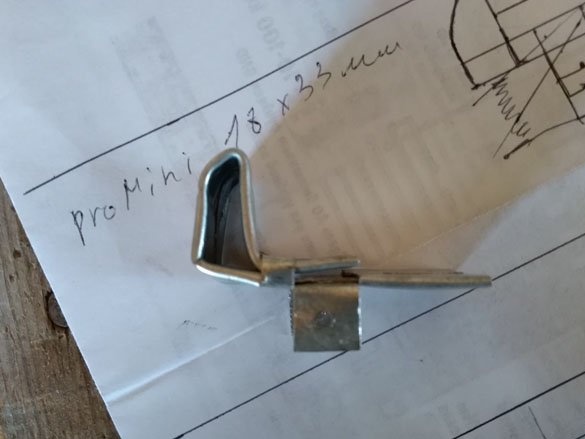
- Arduino (any compatible board, better smaller, for example, Arduino Pro Mini)
- RFID module RC522 13.56MHZ
- Keychain for this module
- Servo SG-90
- connecting wires
- Battery compartment 4 x AAA or battery
- Double sided tape
- Hammer
- Soldering iron and everything to it
- Scissors for metal
- drill
- Metal drill 2.8 mm
- Hot glue
Step 1 Basis of the cache.
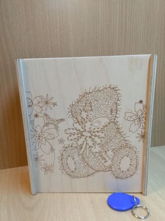
So, a large number of caskets or boxes are suitable as a basis for a cache. I’ll take a wooden box, which comes off by moving the lid up or down, like a “slide”. The dimensions of the casket are 18 x 16 cm and a depth of 5.5 cm. True, part of the space will be occupied by electronics and a latch, but 18 x 10 cm will remain for the cache. I think that’s enough. If you want to repeat exactly my cache - you just need to order a similar box. You can also make it yourself, there is nothing particularly complicated about it, you only need 6 mm thick plywood, a jigsaw and patience.
Step 2 Making the latch.
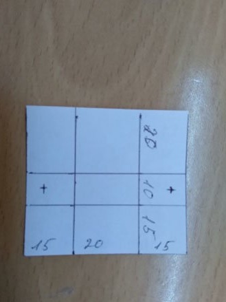
The most time-consuming and complicated is the manufacture of a latch for a casket. This latch is suitable for any cover that slides. We will make a latch from a galvanized sheet. But first you need to transfer the next scan to the paper. A scan is much easier to spread on paper than on a galvanized sheet:
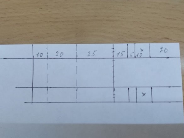
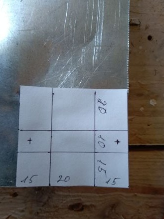
Dimensions are in mm, sweep width 40 mm. Cut this rectangle out of paper. I use double-sided tape to glue a scan to galvanize:
We take scissors for metal (now it is better to put on gloves so as not to cut ourselves on sharp edges) and cut out the rectangle first. Then we make incisions along solid lines, and we will bend along dashed lines.Where the part is folded in half, it should be properly flattened with a hammer. Also in the drawing, crosses mark the places (only two), where you need to make holes of 2.8 mm. The result should be the following:
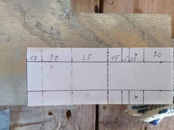
This is the first part of our latch. We pass to the second. We also deal with it, first we make a drawing on paper:
Then, using double-sided tape, glue it to galvanize:
As well as the previous time, we first cut out, and then bend the part. There are also two holes with a diameter of 2.8 mm:
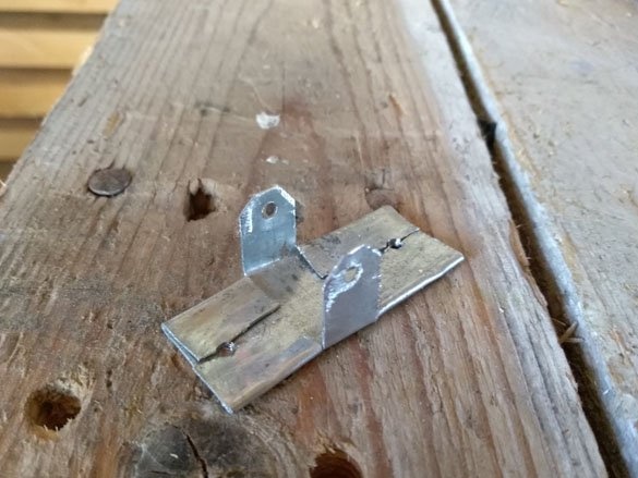
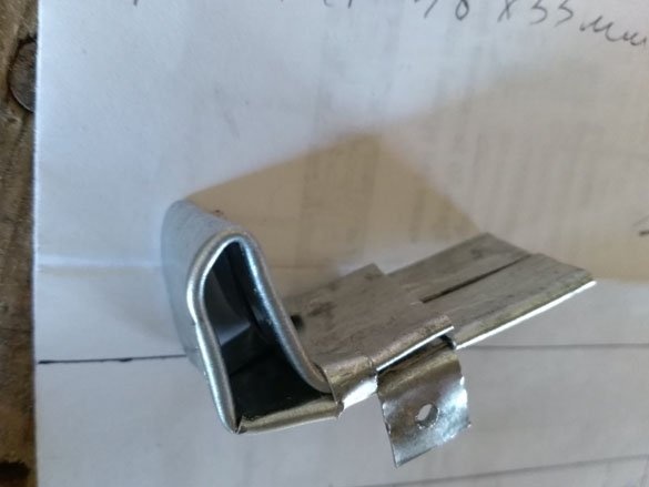
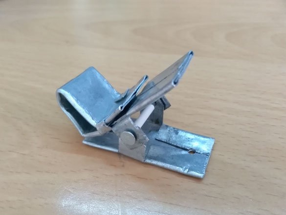
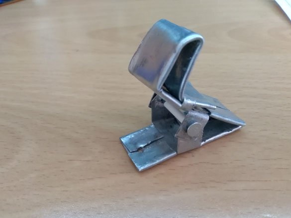
After all that has been done, both parts should be filed to remove sharp edges and burrs. Parts are assembled together using a nail of a suitable diameter:
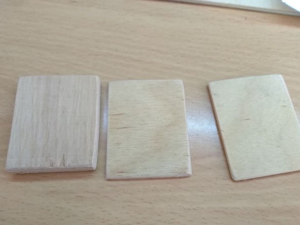
The latch turned out to be of insufficient height, so we cut out rectangles of 5 x 4 cm from plywood, it is necessary to choose so that the upper part of the latch reaches the cover. Lining should be like this:
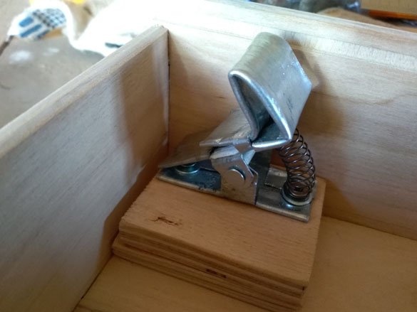
In the upper right corner of the box we glue the required number of pads, on top, I use self-tapping screws or the same hot-melt adhesive, we fasten the latch. It is also necessary to install a spring in front of the latch, so that the latch rises up:
We go further and now take a servo in our hands. We need to set the servo to 90 degrees. You can do this by putting a lever on it, and gently turn it so that the stoppers on the main gear are in the middle. Be careful using this method, it is likely to damage the plastic gears. The second way to install the servo is to fill in the sketch in Arduino, which will set it to the position of 90 degrees, this method is longer, but safer. After the operations done, we put on the servo a small lever that comes with it, so that the lever is parallel to the servo, we screw in the screw so that the lever does not pop off:
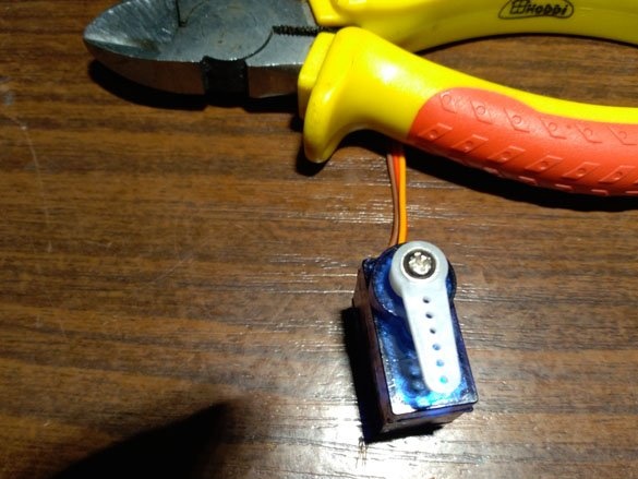
The prepared servo is latched. The lever should go from the center of the latch to the edge:
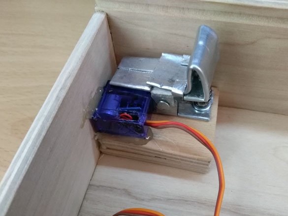
Thus, at a position of 90 degrees, the lever does not touch the latch; when turned through 170 degrees, the lever raises the edge of the latch. In this way, the latch is lowered and we can open the lid.
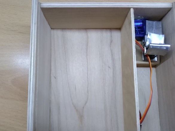
Now we take 3 mm thick plywood or fiberboard and cut out a 18 x 5 cm rectangle. This will be the partition separating the mechanism from the cache space:
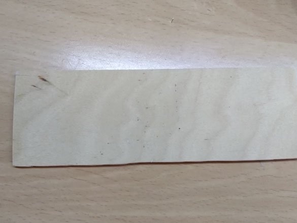
Install it as shown in the photo:
In order for the latch to fix the cover in the closed position, you must install the counterpart on the cover. The reciprocal part will be a 1x4 cm rectangle cut from 1 cm plywood. The counter part can also be made of plywood a little less thick or cut from a suitable board. Or glue a galvanized corner.
Step 3 Electrician.
As I said before, Arduino will manage everything. I have a big box, so I'll take the Arduino Uno. You can take any compatible fee. In my opinion, the Arduino Pro Mini is best suited here. It is the smallest of inconveniences - you will have to use USB-TTL to upload the sketch to it.
We connect the RFID module RC522 13.56MHZ module according to the following scheme:
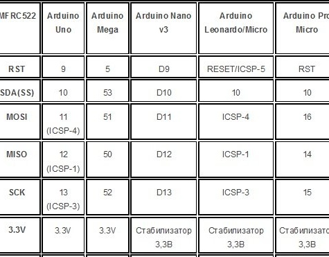
Please note that RFID modules work from 3.3 V.
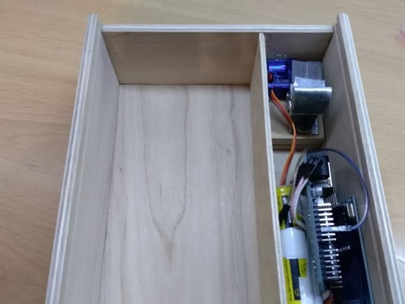
For power we will use 4 AAA “pinky” batteries. We supply power from the compartment with these batteries to the Arduino pin Vin. The servo drive is powered from the battery compartment, and the signal wire from the servo is connected to the D8 Arduino. We place everything inside a place specially designated for electricians and latches:
Step 4 Prepare and fill the sketch.
First, go to Arduino official website
And download the Arduino IDE. Unpack the archive with this program or install using the installer. The sketch uses several libraries. “Servo” - used to control the servo drive:
Download
The second library we need is MFRC522. Download the archive with this library:
Download
Both archives should be unpacked into the “libraries” folder, which is located at the Arduino IDE installation location.
Before final assembly, it is better to fill in a test sketch in Arduino:
Download
Enter 90 in the port monitor first, thereby instructing the servo-driver to turn the lever 90 degrees. Then enter 170 the servo should rotate to a position of 170 degrees and open the latch.
After making sure that the latch works normally, does not jam and the servo drive lowers the latch enough, you can fill in the sketch necessary for the cache to work:
Download