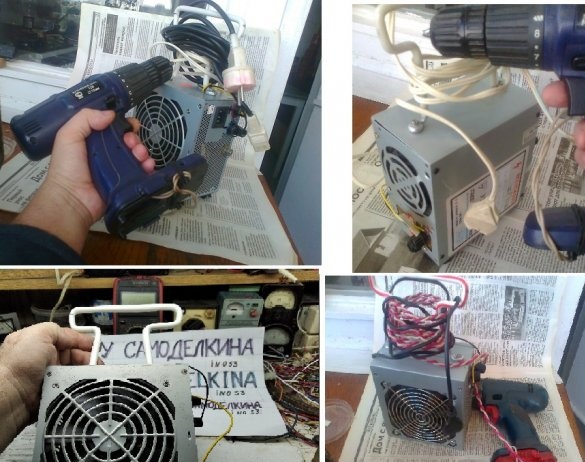
Recently, I was rightly noticed on the forum that I criticize everything, but I didn’t publish anything, not a single one homemade. Well, I am correcting myself and talking about some of my homemade products, those made of computer power supplies. Descriptions are ranked by popularity with garage people.
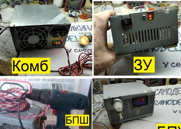
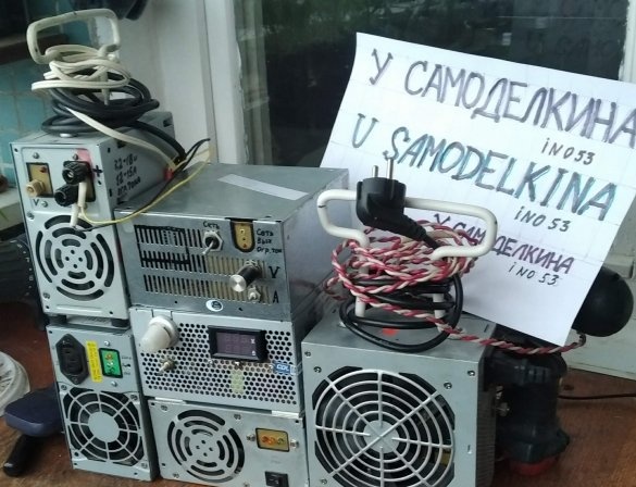
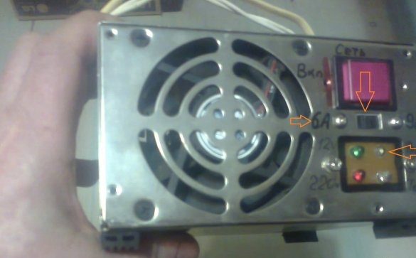
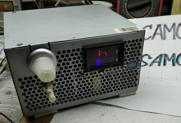
Products at different stages of readiness.
All these products are built on a modular basis. But first about materials and tools.
First of all, you need to have a computer power supply (BP) to turn it into a main module. Externally, the PSUs are all very similar, but the PSUs built on the TL494 PWM controller or its analogue are suitable for us.
. - Quote from somewhere.
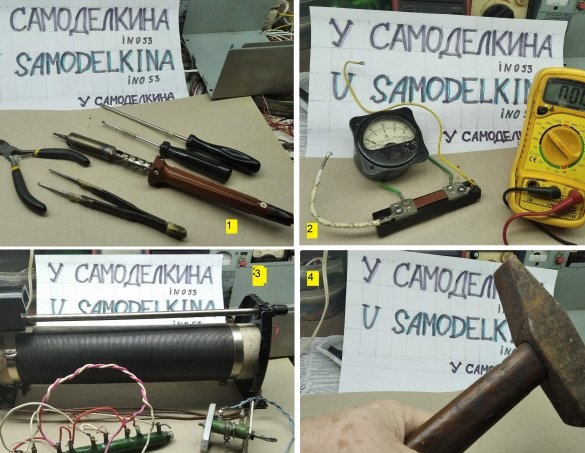
Instruments.
1- The usual set of metalwork and soldering tools. It’s nice to have a soldering station. I recommend a step drill, a convenient thing.
2- Measuring instruments.Of course, such an ammeter is almost a museum, but on the same Ali-Express there are decent digital ammeters and shunts to them.
3- Load equivalents exist electronicbut I have these.
4- In case nothing happens and the nerves can’t stand it.
And now about the modularity of products. The word “module” means a functionally complete electronic circuit that can be physically located on one board, as part of another board, or scattered across several boards. The main module is made of a computer PSU built on a 494 PWM controller or its analogue.
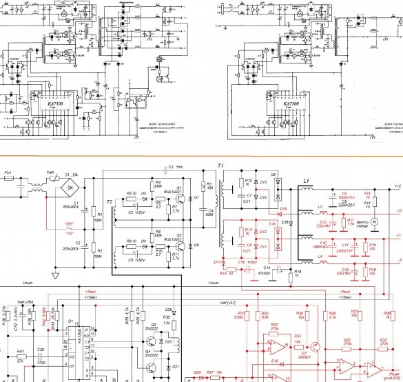
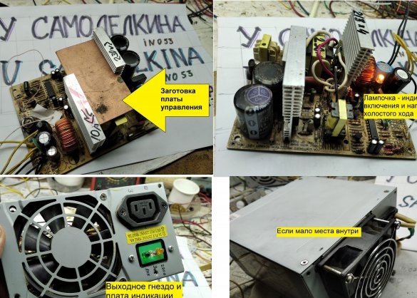
Power supply circuitry has many options, therefore there are many modification methods, they are full on the Internet. Examples of remaking and cleaning the board, see the figure from the Internet. It is not at all necessary to physically remove unnecessary parts; it is enough to disconnect them from the rest of the circuit.
BP refinement examples
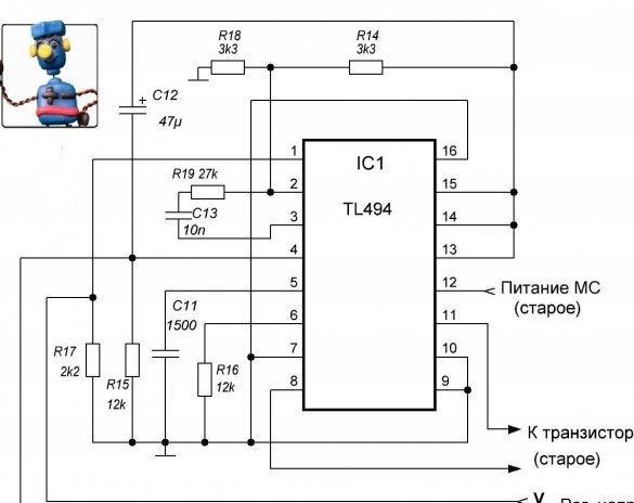
Eventually PWM chip strapping should look something like this.
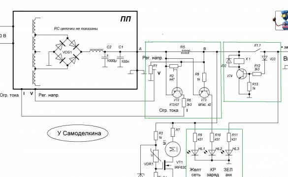
And, accordingly, the BP board turns into power board module (or converter board), let's call it PP.
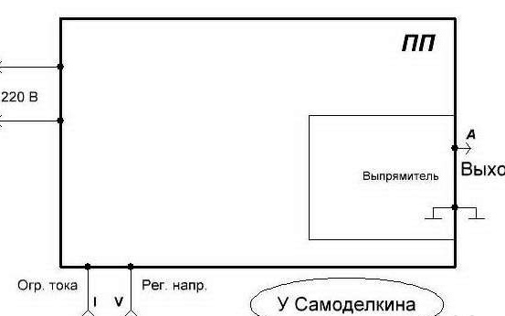
220 V is supplied to the PC, there is an adjustable output and two control inputs - output voltage and output current limiter.
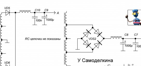
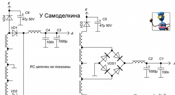
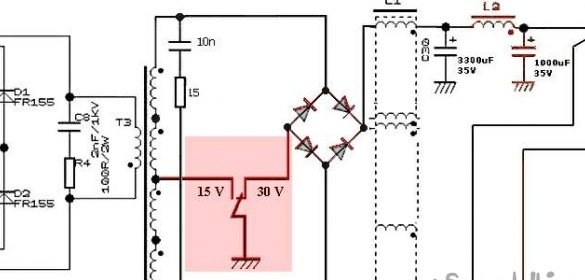
In the PC itself, it is also necessary to finalize the rectifier, first of all, replace the output capacitors with higher voltage ones, if necessary, replace the diode assemblies or assemble the rectifiers according to the diagram below, two options. It should be noted that the assemblies on SB35L40PT Schottky diodes, etc., installed in the 5-volt channel, although they have an allowable voltage of 40 V on the datasheet, sometimes break through perfectly with a rectified voltage of 14 ... 16 V, as a result of which transistors fly out on the high side. The emissions in the voltage coming out of the transformer can exceed 60 V, therefore we use assemblies and diodes not less than 100 - volt.
Rectifiers, two options.
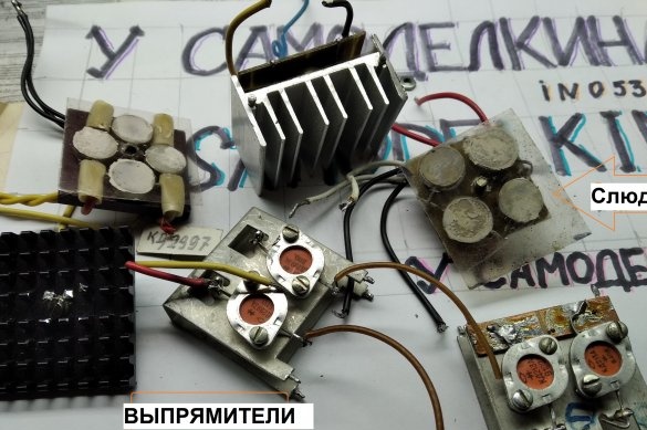
Capacitors even in the memory, where the voltage does not exceed 15 ... 16 V, it is advisable to put 25-volt. There were recommendations - instead of a single capacitor of large capacity, put several pieces of a smaller capacity, such as improving cooling and parallelizing the ESR. Perhaps only space is usually not enough. I use diodes KD213 (up to 10 A) and KD2997 (up to 30). The group stabilization inductor uses the former 5-volt winding. In general, it is not worth giving up the DGS, although it is warming slightly, without it, the operation mode of the input transistors worsens and their heating increases.
Rectifiers
Adjustment module
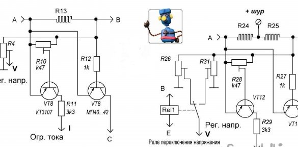
There are two options - one level for current limitation and voltage regulation, for the memory, control panel and BPSh, and two for COMBIC. The basis is a current sensor, on which, when current flows, enough voltage drops to open the control transistor (KT3107 or any direct silicon), the appearance of voltage at the Deadtime Control input (4 legs), while the output voltage decreases and the current cannot exceed the set limit. As a rule, for the memory, the resistance of the current sensor is about 0.15 ... 0.2 Ohms, for the BPSh it is about 0.07 Ohms, in the control room to expand the limits of adjustment of the current limit to low currents of 0.25 Ohms or more, and for COMBIC two-section shunt - charging current flows throughout the shunt, the screwdriver’s current only in part of it, about one third of the nominal value. At the same time, if the charging current is limited to 5 amperes, then the screwdriver current is -15 (it will actually be less, because at high currents the nichrome heats up and increases its resistance).
The second transistor is a direct germanium one, its opening voltage is much less, it is open when a relatively small current flows and indicates its flow.
Current sensors
I use the most accessible material for the sensor - nichrome with a diameter of 1.0 and 1.2 mm. For high currents - a strip of tin from a can.
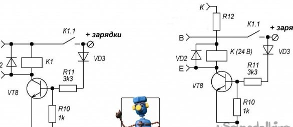
Protection module for the charger and COMBIC, it allows the connection of the load (car battery) only if there is a positive voltage on it. With a short circuit and a polarity reversal, the relay simply does not turn on. Automotive Relay, 12 (14) V.
Option (right) is to use a 24 ... 27 V relay. In this case, you need to add two parts to the rectifier. Resistor R12 is selected for specific modes.
When the protection relay is switched on in COMBIC, the voltage switching relay connected in parallel to it also works.
Display module. It shows the presence of a 220 V network (or rather, the operability of the PCB), the correct connection of the battery (green, inscription 12 V), the flow of charging current above about 0.5 ... 1 A (depends on the current sensor).
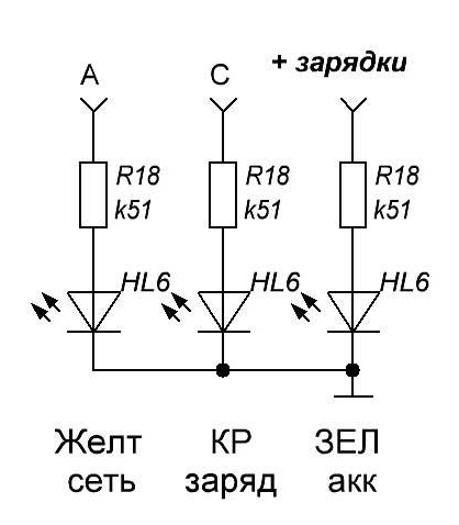
For all products, the presence of the "220" LED is optional, it is enough to install it on the PCB (see one of the following figures), its glow is clearly visible through the grilles. For BPSh, only it is needed (or an LED), and the BPU has a luminous multimeter.
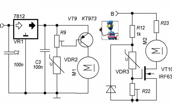
Next - cooler control module (sorry, Ivan_Pokhmelev
The option on a bipolar transistor (left in the diagram) is good with an output voltage above about 16 V, as well as the fact that the thermistor is tied to ground and you can not bother with its insulation (not always!). In general, this entire module can be replaced with one selected resistor.
Now let's see what can be assembled from these modules.
Let's start with memory.
In my opinion, there is nothing to comment on.
A variant with switching the current limit to the forced mode is possible. An additional switch connects a pre-selected resistor between the base and the emitter of the KT3107 transistor, the cascade sensitivity is roughened and the charging current increases
Dual-mode memory.
COMBICA operation in the charger mode (battery charging).
When connected correctly to the charging battery, the green LED lights up, , whether the network is on or off. When the network is turned on, yellow 220 V and if red lights up CURRENT, then it’s charging. After a while, when warming up, the cooling fan will hum. When charging is completed (possibly in a few hours), the voltage on the battery will reach the desired level, there will be a transition to constant voltage charging mode and the current will begin to decrease, the red LED will gradually go out. If there is no rush, it is advisable to keep the battery on charge for a couple more hours after it goes out, microcurrents will recharge.
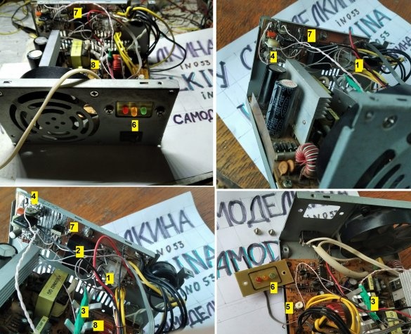
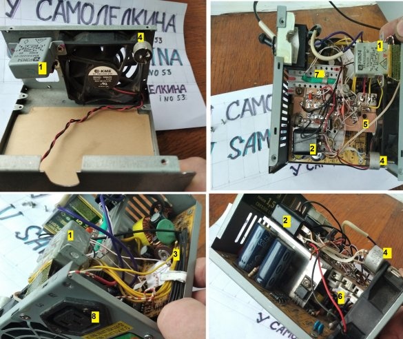
View of the memory from the inside.
1-current sensor.
2-relay protection.
3-thermistor in heat shrink.
4-Regulators limiting the current and revolutions of the cooler.
5-charge voltage regulator.
6-Indication Board.
7-The control board, on which everything is assembled, is mounted on the rear wall.
8-Radiator rectifier.
I do not have professional photo equipment, so sorry for the quality.
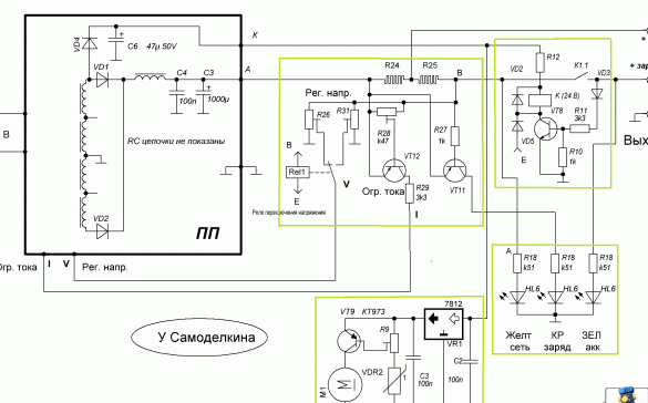
COMBIC, diagram and inside view.
Shown is a circuit variant with a 24 V protection relay.
1-relay protection.
2-relay voltage switching.
3-charge voltage regulator.
4-voltage regulator screwdriver.
5-control board.
6-Dual current sensor.
7-thermistor in heat shrink.
8-output socket.
Next about power supply unit BPSh screwdriver.
The simplest product in this series, in addition to updating the software, you only need an adjustment module, even without indicating the current. It is advisable to install on the PC indicator light on and the load XX.
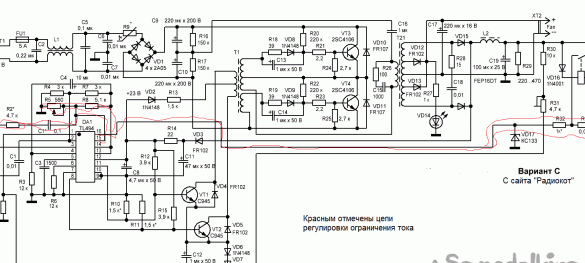
It should be noted that for the BPSh and BPU circuits, since they do not use the indication of the charging current, it would be more correct to use the current limiting circuit from the memory from the Radiokot website, the author is someone from Borodach (borodach) or Old Man (Starichok51), or maybe the Falconist (falkonist), I do not remember…
Red indicates the current limitation adjustment circuits. In this circuit, the current sensor has an order of magnitude lower nominal value, respectively, less loss. Used previously unused op amp (inputs 15.16), fewer additional parts. However, the introduction and configuration of additional op-amp correction circuits is a painstaking operation and does not always succeed.
The work of two screwdrivers from one BPSh. If there is no problem with the same voltage, we connect in parallel and work, of course, alternately, not simultaneously, do not forget to monitor the possible overheating of the unit. If at different voltages, for example, 12 and 18 V, we put an additional plus terminal (minus the common) and a wire suitable for it, we make about a dozen turns around the reed switch.When you turn on the extra shurik from the flowing current, the reed switch is triggered, turns on (as in COMBIC), which switches the voltage regulators.
Finally - universal power supply unit BPU.
Well, of course, universal - it is said loudly. The minimum output voltage is approximately 2.5 V, the maximum depends on the type of rectifier (without rewinding the transformer, squeezed up to 48 V).
-
The maximum current displayed on the digital multimeter is 12 ... 13 A (I have not tried it anymore, and so I burned one), we are limited to this value. The minimum current limit level depends on the current sensor. The quality of the output voltage is ripple, stability is mediocre, but the garage is not a laboratory either. The control unit with the photo now heats the nichrome wire in the foam cutting installation.
Rectifier Option
In these products (BPU) it is recommended to use the ATX format PSU, in the rest the AT format also works.
Some design details for all products.
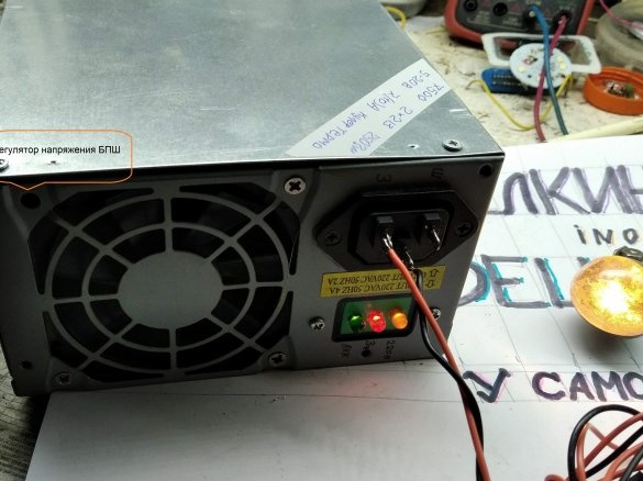
-The voltage regulator on the front panel causes an ardent desire to twist it, as a result of which it is good if 6 ... 8 V goes to a 12-volt instrument, and if 18 ... 21? Therefore, we hide the regulator in an inconspicuous hole (sorry, holes).
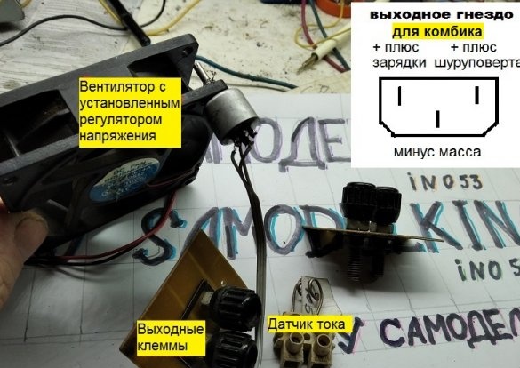
- Threaded output terminals are a good thing, but you won’t confuse polarity with a three-pin socket even if you really want to.
- The current sensor is nichrome, it does not solder well, it does not get hot during operation, so we use a regular terminal strip, preferably carbolic, to fix it, and closer to the fan.
- There are few places, so we fix the control board where it works.
- The indicator lamp and three-pin socket mentioned in the text.
-If there is little space inside ...
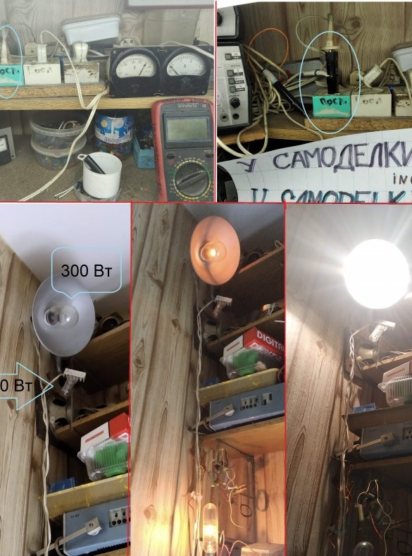
And the last one. For many designs, the first inclusion is also the last, by myself I know. Widespread recommendation: the first inclusion of the product in the network - in series with an incandescent lamp. I have been using this method for many years as follows. In the upper left picture we see an extension cord for three outlets. The right one, grimacing, is turned on in the usual way, and the left, green, and middle ones are turned on sequentially. In the middle through an ammeter and a voltmeter, a socket is connected to connect the tested designs. But in order for voltage to appear in it, it is necessary to turn on the light in the left one. I have 3 of them - for 100, 300 and 750 watts. You can turn on the lights in any combination - on the left photo one is on, on the right - all three. The best for this purpose are halogens, they have low resistance in the cold state and a sharp increase in it - up to 10 times - in the worker.
In the bottom left photo, a small current goes through three hundred, the lamp does not affect the load. (The 100 W lamp is not visible, it hangs below). In the average photo, the load is 300 watts, the limit mode. On the right - short circuit in the load. If it weren’t for this protection, I would have had to go out onto the landing in the dark, open the flap, click the machine gun, then set the time in the clock and TVs, while listening to the wife’s completely fair abuse and thinking what could burn out in the structure. Protection is useful.
That's all, comment.


