
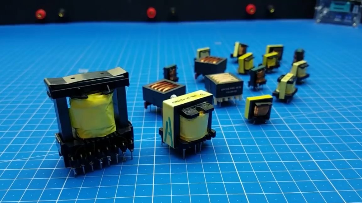
As you know, a transformer is the main element of any power source. Novice hams quite often ask themselves the question: how to properly wind the transformer yourself? Therefore, this instruction is fully devoted to the calculation and winding of a pulse transformer.
So, let's start, but not from the transformer itself, but from the control circuit. It often happens that people take any transformer that comes to hand and begin to wind their windings on it, without thinking about one small, but very important part, which is called the gap.
There are 2 main types of transformer control circuitry: single-stroke and push-pull.

From the figure above it can be seen that the push-pull include: bridge, half-bridge and push-pool. In these schemes, there should be no gap in the core, and this applies not only to the power transformer, but also to the TGR.
As for single-cycle circuits, they are straight-through and reverse-flow, so they must have a gap in the core, so the first thing is always to be more thoroughly familiar with what you are doing.
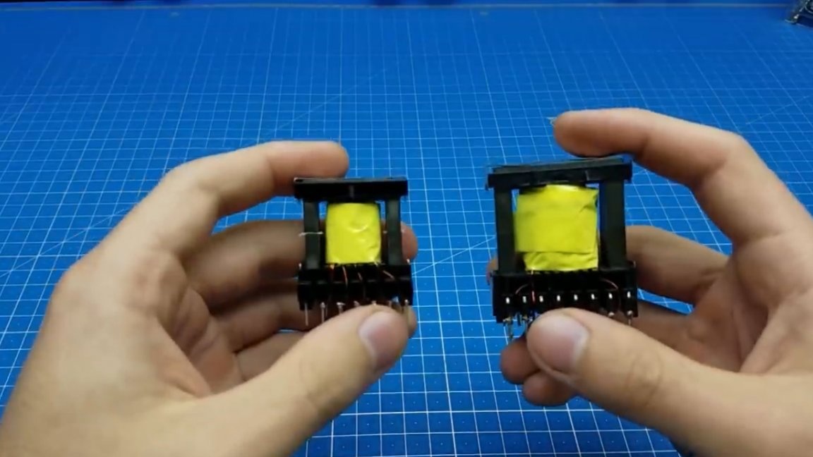
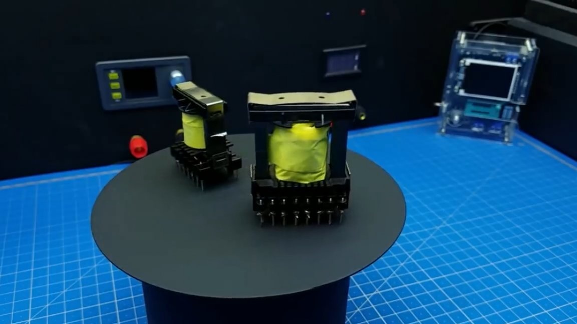
For a more illustrative example, in this article we will consider the winding of 2 different transformers, one for a push-pull circuit, the second for a single-cycle, respectively.
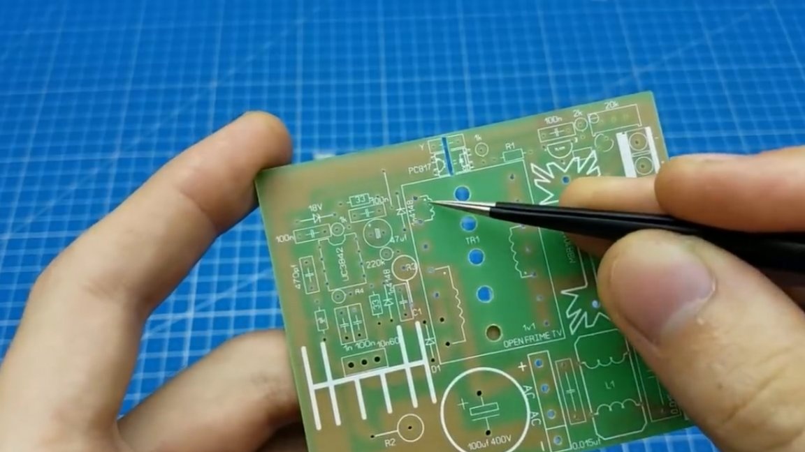
The author decided to wind the transformer for finished projects. The first is a block on the SG3525. The scheme is presented below.
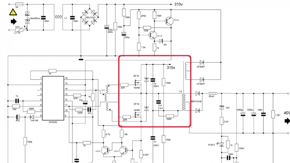
As we see from the diagram, this is a half-bridge. Thus, this type belongs to the category of push-pull circuits, therefore, as mentioned at the beginning of the article, a gap in the core is not needed.
We decided on this, but that's not all. Before winding, it is necessary to perform special calculations (calculate the transformer). Fortunately, on the Internet you can easily find and download special programs of Vladimir Denisenko for calculating the transformer.
Thanks to the author of these programs, and he has far from one, the number of self-made power supplies is constantly growing. You can familiarize yourself with all the programs of this author, but in the example we will analyze only two of them. The first is “Lite-CalcIT Calculation of a pulse transformer of a push-pull converter” (Version 4.1).

We will not go into details, we will only touch on important points. The first is the choice of the converter circuit: push-pool, half-bridge or bridge.Next, we have a line for selecting the supply voltage, it is also necessary to indicate it, you can specify either an already rectified voltage (constant) or just a network (alternating). Below is a field for entering the conversion frequency. Usually, in his projects, when calculating power supplies, the author sets the frequency in the region of 40-50Hz, you do not need to raise it higher. Next, indicate the characteristics of the converter. In the appropriate columns indicate the voltage, power and wire, which will be wound. Do not forget to specify the rectification scheme and check the "Use the desired parameters" box.

In addition, the program contains 2 more important fields for filling. The first is the presence or absence of stabilization.

When the checkmark is turned on, the program automatically throws a couple of turns on the secondary for the PWM operation clearance.
The second field is cooling. If it is present, then more power can be squeezed out of the transformer.
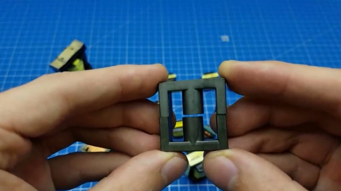
And last, but most important, you must specify which core will be used when winding this transformer.
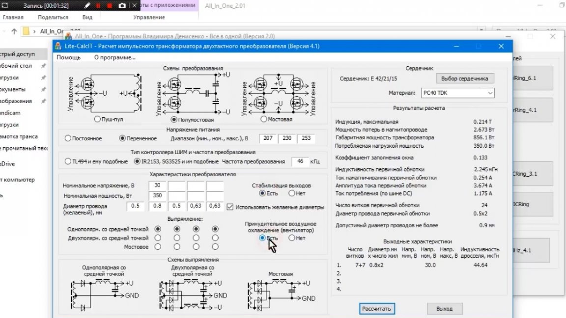
Most standard denominations are already entered in the program, it remains only to choose the necessary one.
And now, when all the fields are filled in, you can click the "Calculate" button.

As a result, we obtain data for the winding of our transformer, namely the number of turns of the primary and secondary together with the number of cores.
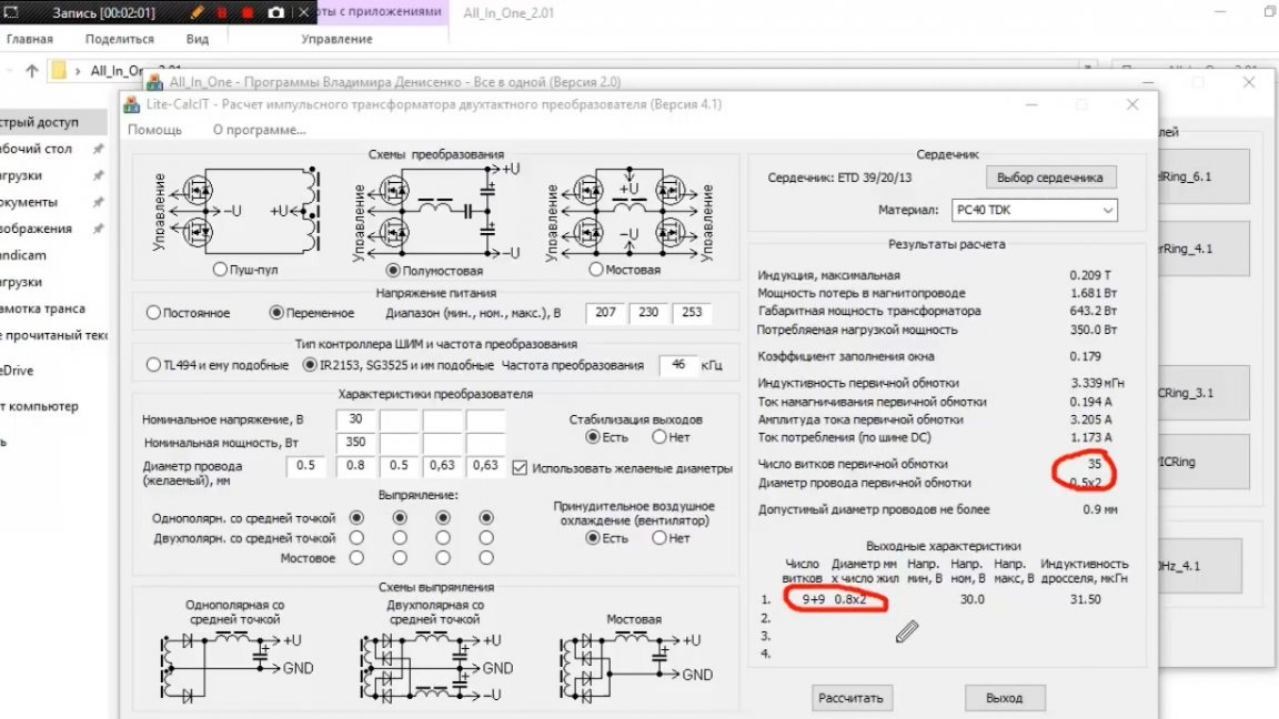
The necessary calculations are made, you can proceed to the winding.
An important point! We wind all the windings in one direction, but we start the beginning and end of the winding strictly according to the scheme. Example: suppose we put the beginning of the winding here (more on the image below), wound the required number of turns and made a conclusion.
Let's visualize how current flows. Let's say it flows like this:
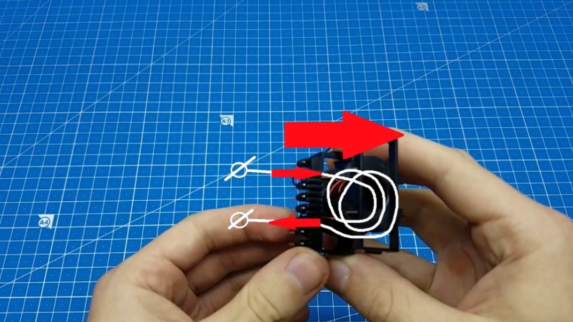
Then it will flow along the wire in the indicated direction. And now we just swap the beginning and end of the winding.
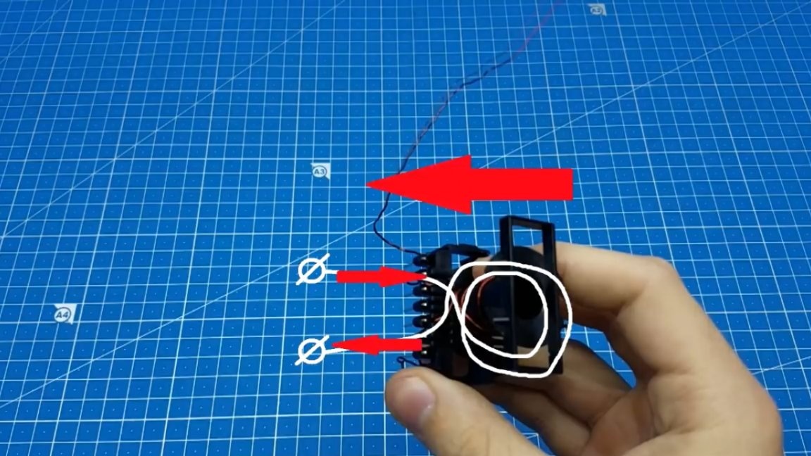
Although the winding was done on the right, the current will flow in the opposite direction and this will be equivalent to the fact that we wound the winding to the left. Thus, phasing can be easily carried out at points on the circuit; the main thing is to wind all the windings in one direction.
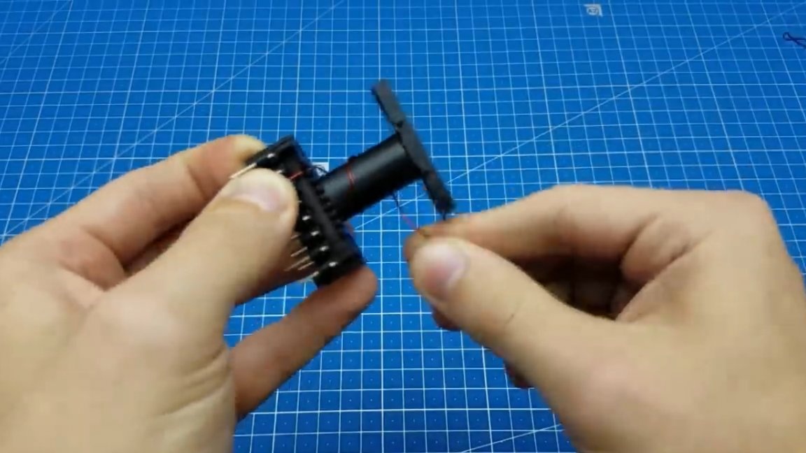
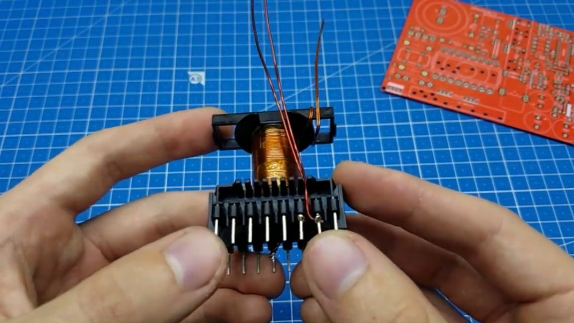
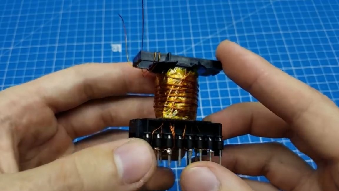
With an example figured out, proceed to the real winding. The beginning of the winding is at this point (see image below), which means we will wind from here.
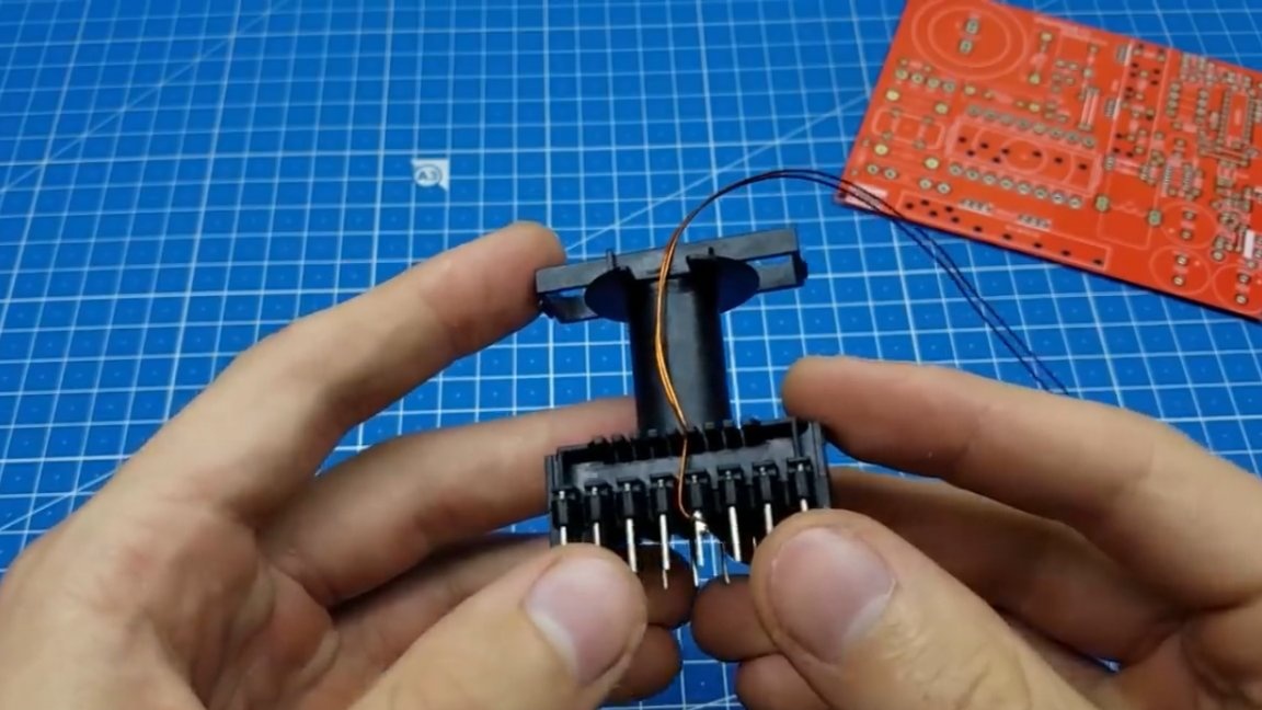
We try to evenly lay the turns, it is also necessary to avoid the intersection of the wire and various knots, loops and the like. The further operation of the entire power supply depends on how you wind the transformer.
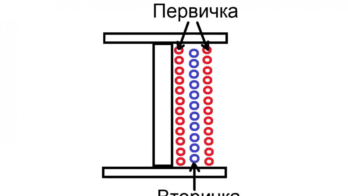
We wind exactly half of the primary and we retract, not directly to the transformer pin, but up. Next we will wind the secondary, and on top of it the remaining primary.
Thus, the magnetic coupling of the windings is increased and the leakage inductance is reduced.
Between windings must be used isolation. This one is perfect thermal tape.

And for the very last layer of insulation you can use mylar ribbon for beauty.

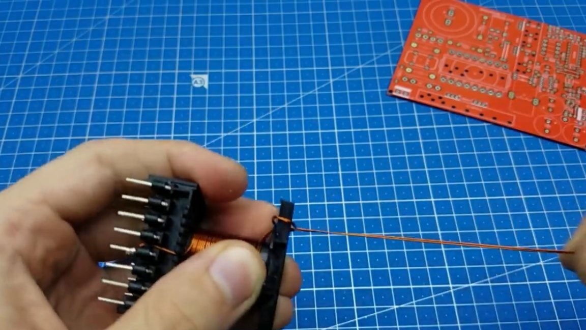
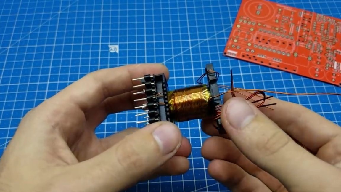
The secondary winding is wound in the same way as the primary.
We solder to the beginning of the winding and evenly wind to the coil. In this case, it is desirable that the secondary fit in one layer. But if you calculated on a greater tension, then it is necessary to stretch the second layer evenly throughout the frame.
When the layer is wound, then again we make a retraction upwards and begin to wind the second part of the secondary. It is wound in the same way as the first.
Here it is already worthwhile to mark in some way where you have the first half of the secondary and where the second.
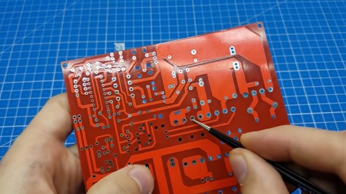
The next step - homework of the primary winding. In this case, the author usually leaves himself an empty pin on the circuit board, so that you can connect the midpoint of the primary.
Here, with this pin, we begin to wind the remaining primary, everything is also uniform.
Here it is already not necessary to tilt up the end of the wire, you can immediately bring it into place.
Then we carry out the same operation for the remaining conclusions.
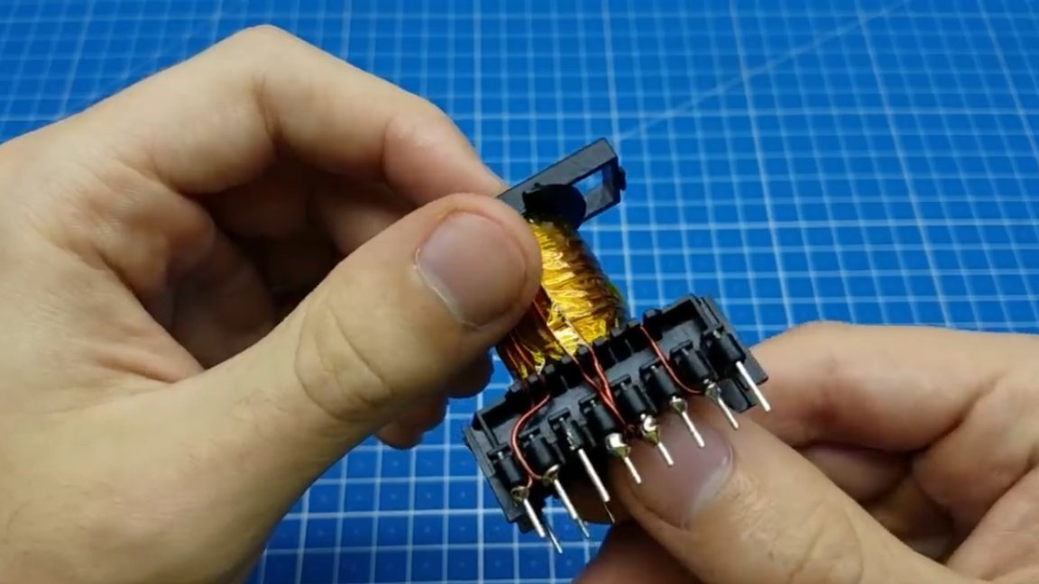
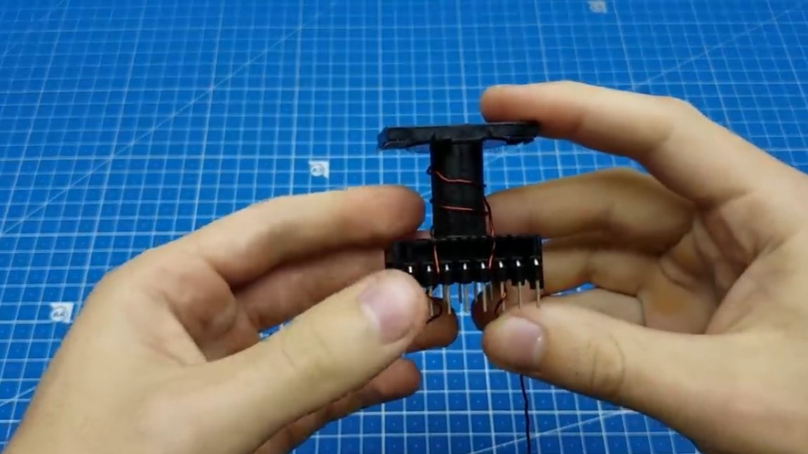
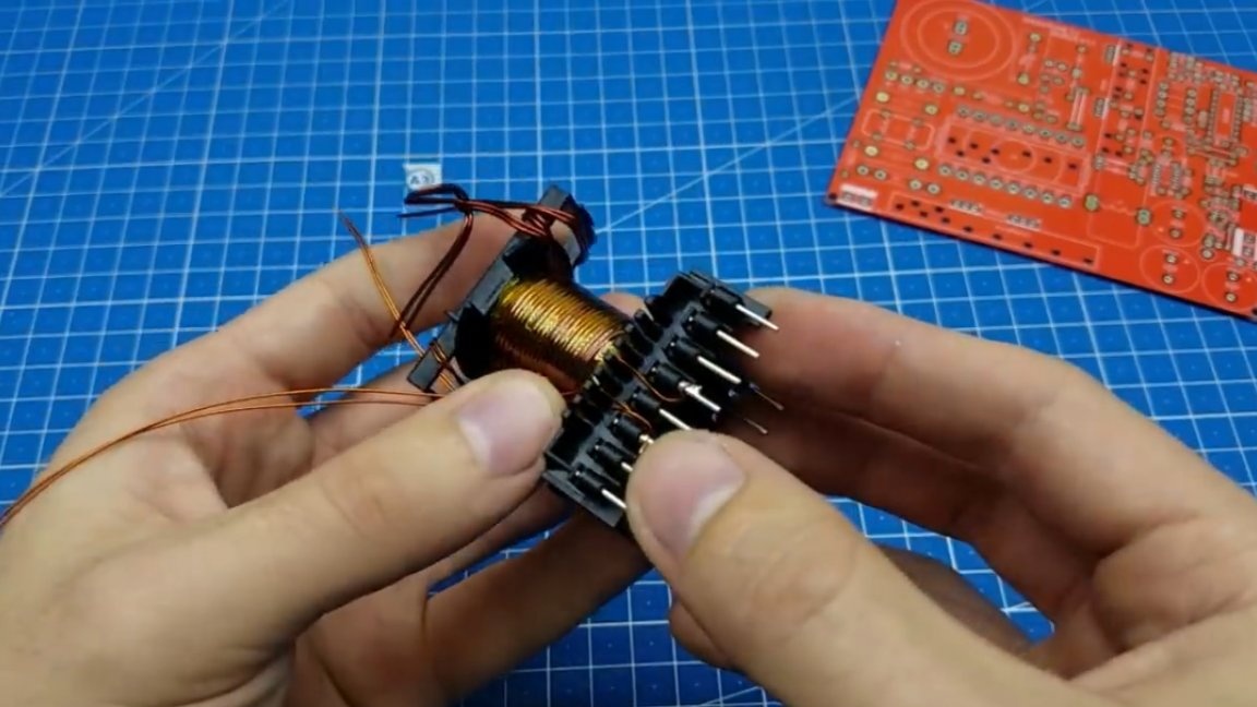
When the main windings are finished, you can start winding additional ones, in this case it is a self-winding winding. Everything is exactly the same with it, the beginning and the end are indicated on the printed circuit board, isolate and shake.
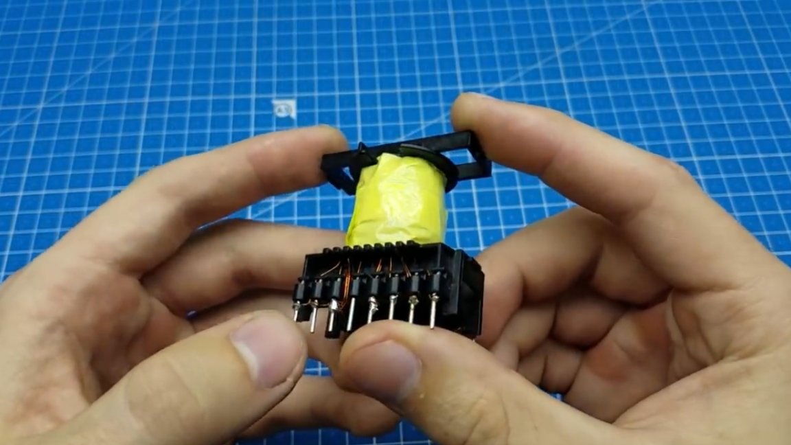
The top layer, as mentioned earlier, is covered mylar ribbon. Now, now the transformer looks like an industrial design.
Note for beginners! As a rule, beginner hams make their first power supplies unstable on chips like IR2153 and constantly encounter the following problem: they say they wound one voltage and got another at the output. Rewinding does not produce results. What is the matter? But the fact is that it is necessary to carry out measurements at a load of at least 15% of the nominal. And it turns out that the output capacitor is charged to the amplitude value, you actually measure it, and you can not understand what is wrong.
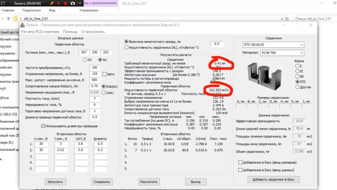
The winding of the flyback power supply transformer is no different from the previous one, only for calculation we will use another program from the same software package - “Flyback - Flyback Converter Transformer Calculation Program” (Version 8.1).
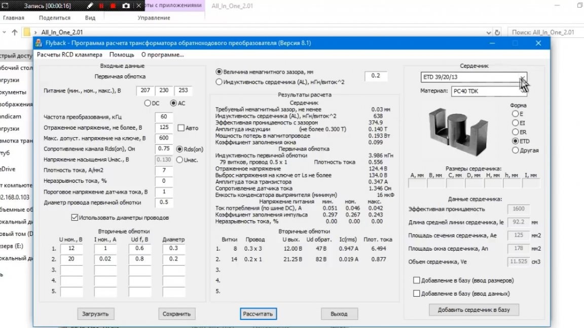
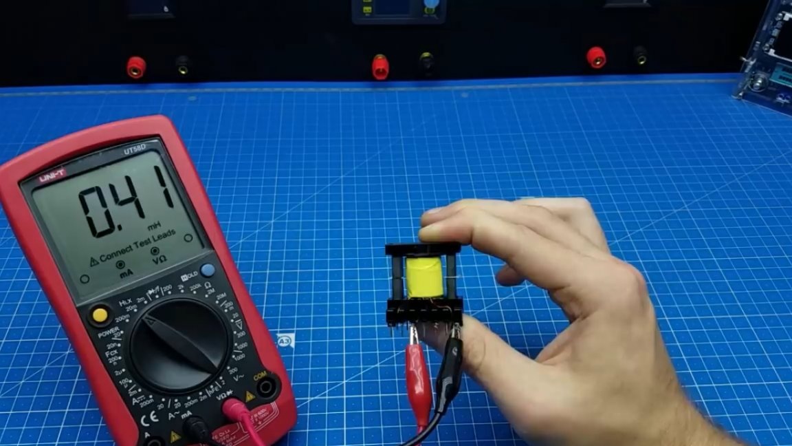
We indicate the necessary parameters: frequency, output voltages, and so on, this is not so important. The only point that deserves special attention is the gap in the core and the inductance of the primary winding. These parameters will need to be observed as accurately as possible.
That's all. Thank you for attention. See you soon!
Author's video: