
From the article below you will learn how to do it yourself make a piston engine out of wood. The following description and instructions are taken from the Matthias Wandel YouTube channel.
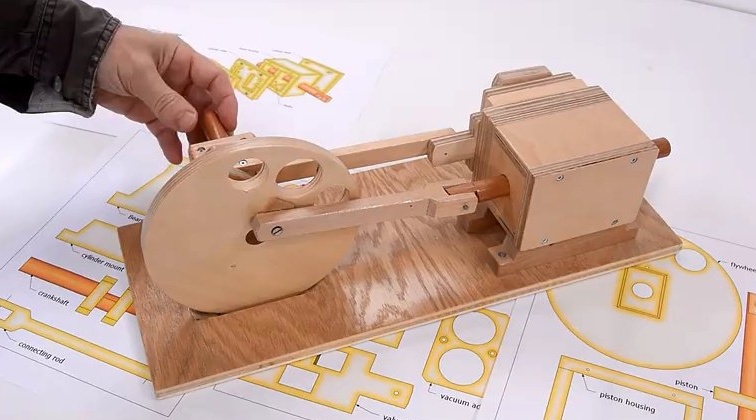
One of the friends of the master is a modeler - designer. He creates various models of ships, cars and various power plants. It was he who asked his friend to make model A wood engine piston that runs on compressed air.
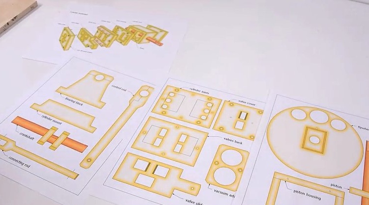
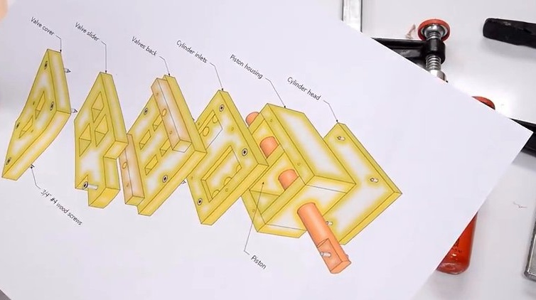
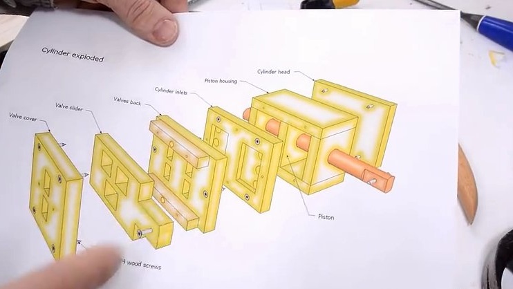
Here is an example drawing and details of this engine.
To manufacture this engine, the following materials and tools were required:
- a small piece of plywood 10 mm .;
- wooden block;
- band-saw;
- a chisel;
- clamps;
- drilling machine;
- drill 4 mm;
- Forstner drill;
- mallet;
- PVA carpentry glue;
- varnish;
- a planer;
- a pencil;
- awl;
- 38mm screws;
- cutting knife;
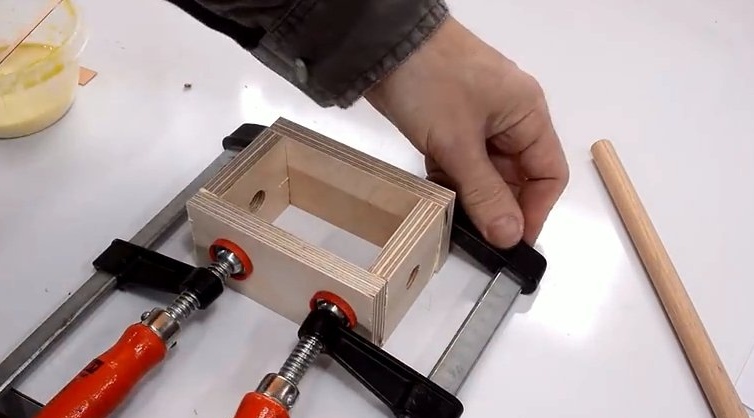
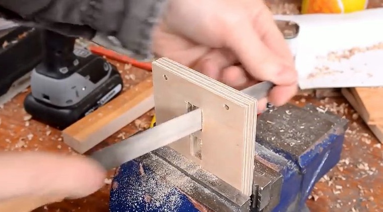
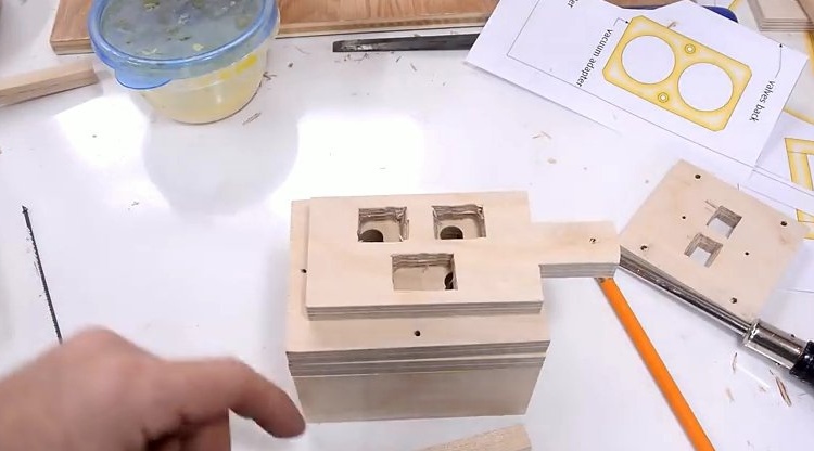
Production of cylinder parts from plywood.
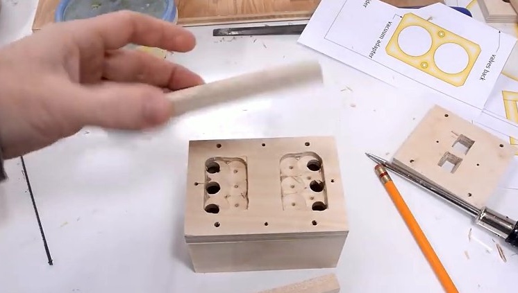
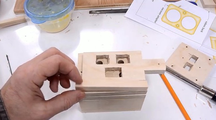
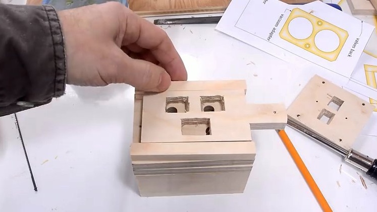
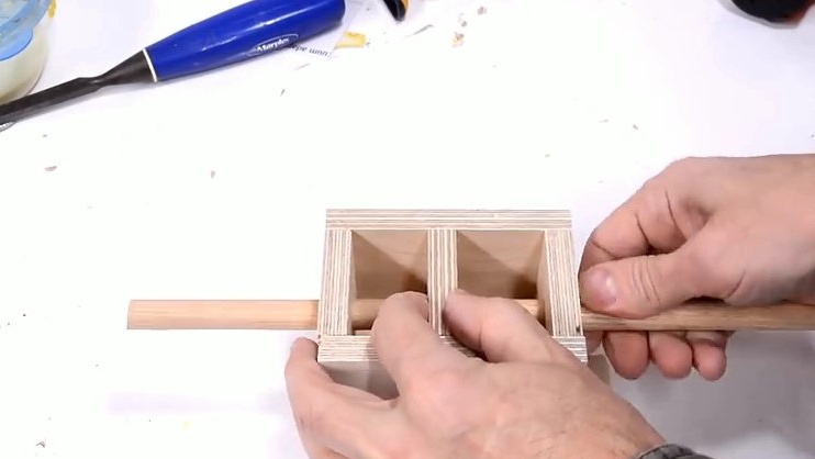
Phased assembly of cylinder parts.
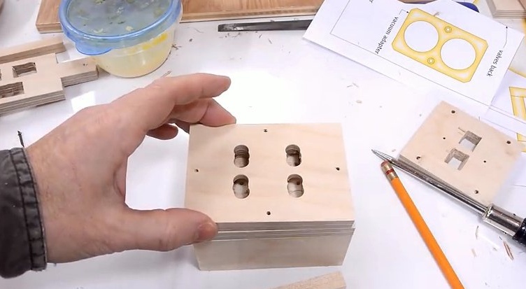
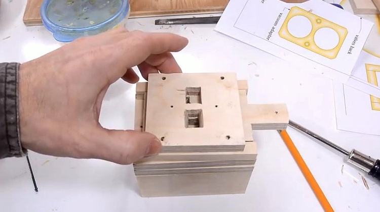
The view from the back.
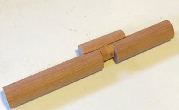
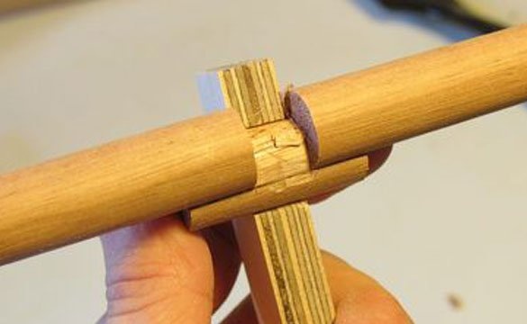
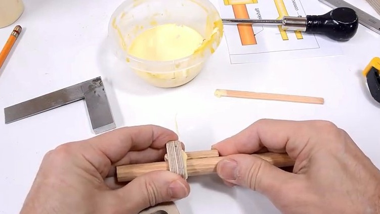
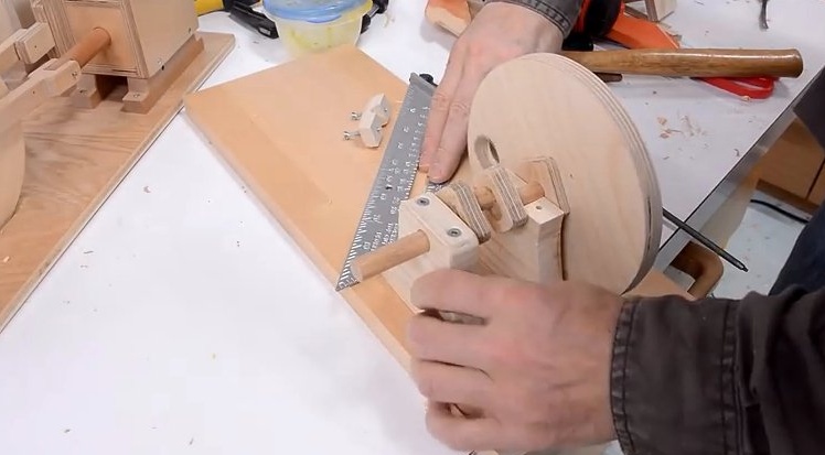
One of the most difficult parts to produce in an engine is the crankshaft. The crank mechanism of the engine is actually located in close proximity to the flywheel, but an additional mechanism is needed to actuate the valve assembly. This secondary assembly consists of a 6 mm bar. The master made it by gluing a piece of the pin to the main shaft. The second part of the pin is cut in the form of a crescent in cross section, which allows it to fit snugly against the shaft. After that, part of the main shaft was cut to the required length.
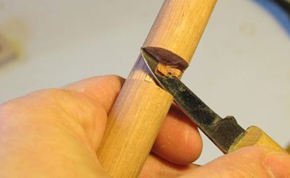
The initial cut was made with a band saw, and the rest was carefully cut by hand.
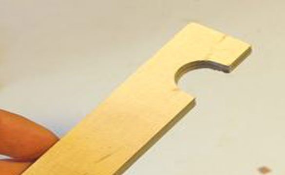
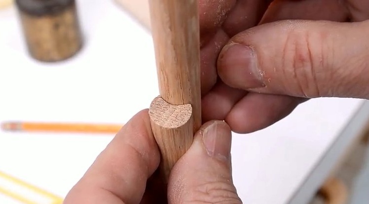
The guide is made of plywood, in which a hole is drilled from the edge. Then the hole is cut in half. Thus, a template was made to find out how much more material needs to be cut so that the parts are flush.
Firmly pressing the guide to the cut section and turning it back and forth, the master saw the shaft sections from which it was necessary to remove the material.
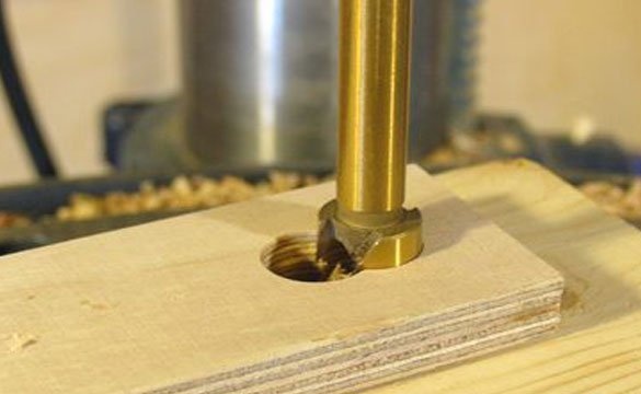
As soon as the master was convinced that the middle part of the crankshaft was quite round, he made two reinforcing plates, which he was going to stick on either side of it. He drilled two 15 mm holes in plywood with a center distance of 6 mm. After that, a rectangle was cut around these holes.As a result, the parts obtained were glued to the crank. Gluing these pieces was a simple matter - you just had to push them from the ends of the crankshaft.
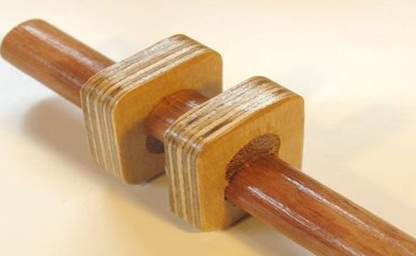
Ready crankshaft (after varnishing)
The crankshaft bearing blocks consist of two parts. To make sure that all the holes were perfectly aligned, the master clamped both halves of the bearing together, and then drilled holes for the screws through them.
After screwing the upper part of the bearing block, the master drilled a hole for the shaft through both parts. He used a 15 mm drill. After drilling holes, the master cut out the entire block of bearings with a band saw and rounded corners on it.
The master used the same approach to cut holes in the connecting rod. First he twisted the parts together, and then drilled a hole in the assembled rod.

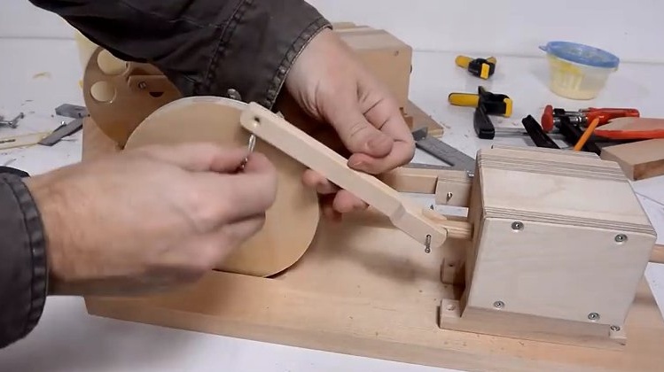
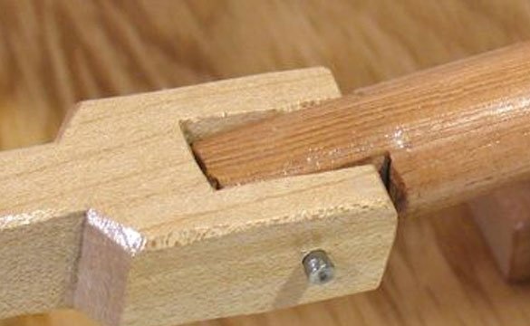
Crankshaft with connecting rod.
Flywheel with crankshaft. The flywheel is cut out of plywood. It has holes for balancing.
To connect the flywheel to the crankshaft, a small glued piece of plywood is used, to which the crankshaft is attached with a screw.
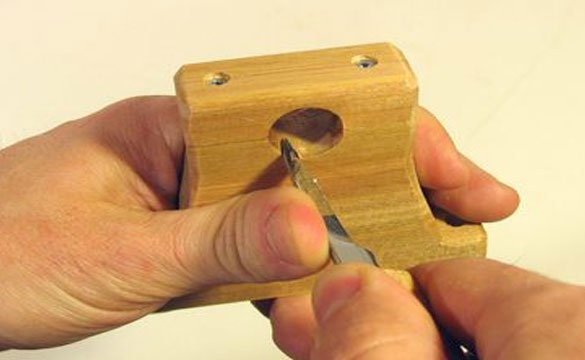
In the end, the master slightly adjusted the bearings, cutting a very thin layer of wood from the inside with a cutting knife. This procedure had to be repeated again after everything was painted, since the varnish added a little thickness.
Mounting the crankshaft in bearings on plywood - stand with self-tapping screws.
The cylinder and piston are made rectangular.
There are no piston rings or seals around the piston, so there are “purge holes”. This engine is not designed for high power and efficiency, so everything is in order. Ideally, there should be a small clearance around the piston to reduce friction, approximately 0.1 mm. The master made a piston so that he did not have a gap, and then polished it a little.
There are no gaskets in this assembly. Details are simply screwed together. This is enough to reduce gas leakage to an acceptable level - of course, there are much less leaks around the cap than around the piston.
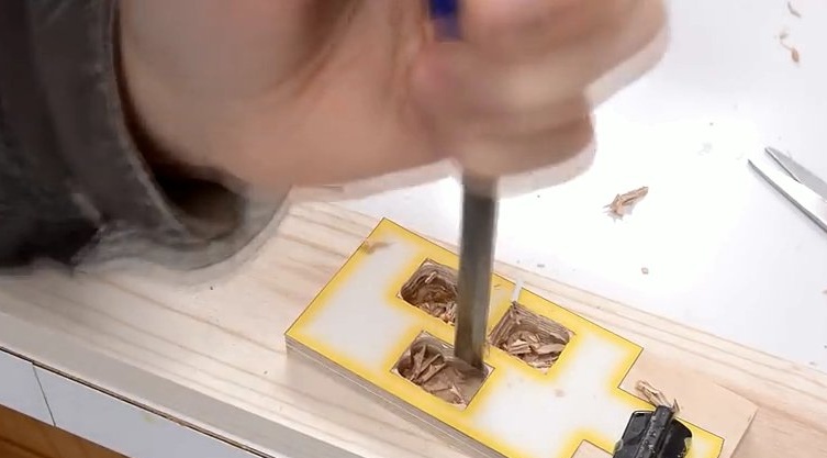
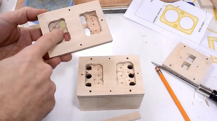
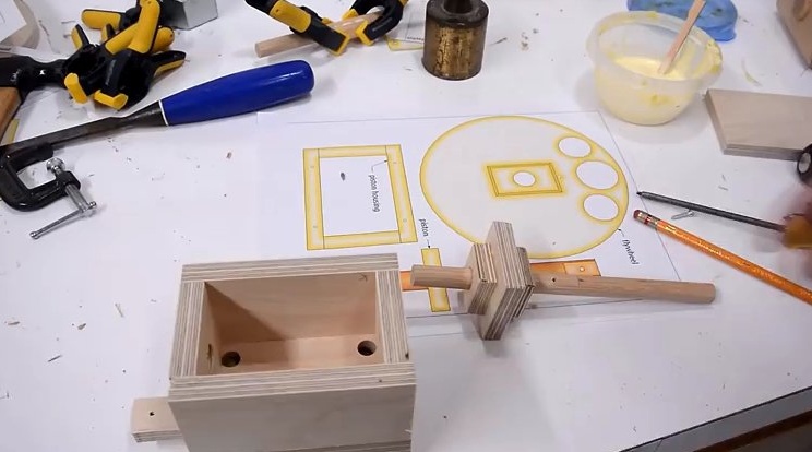
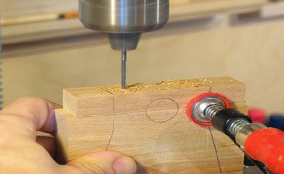
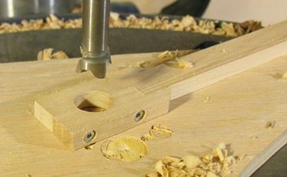
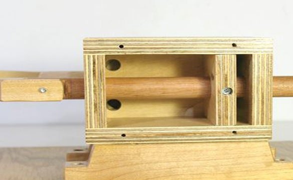
The image shows holes in the rear of the cylinder for air inlet. The air inlets for the piston should be directed towards the ends of the piston, but the valve assembly needs to be inlets together so that an inner channel is formed between the two parts of the plywood, by cutting out the layers of plywood. The master made these cavities with a Forstner drill. They are not visible when the engine is assembled, so this is not critical.
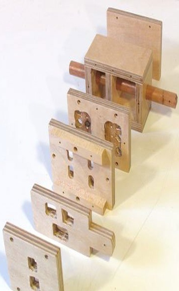
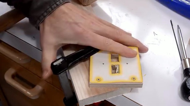
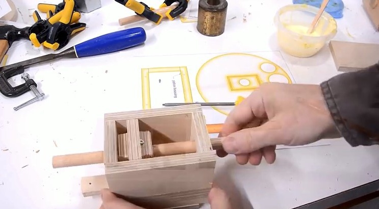
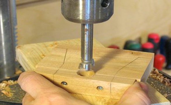
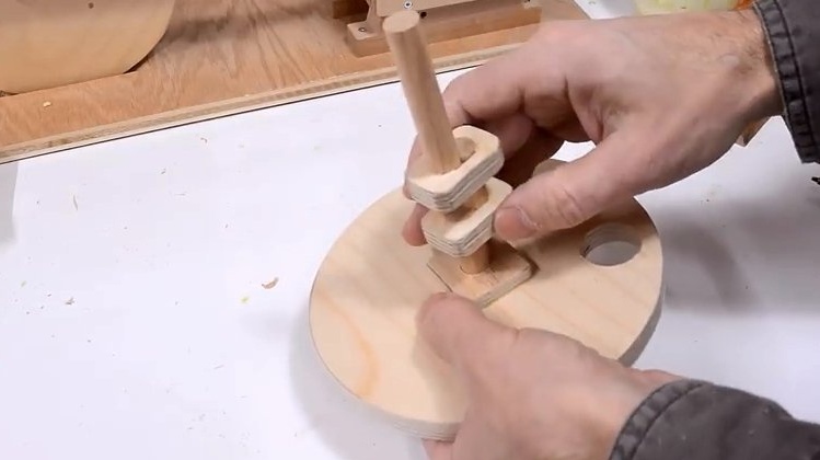
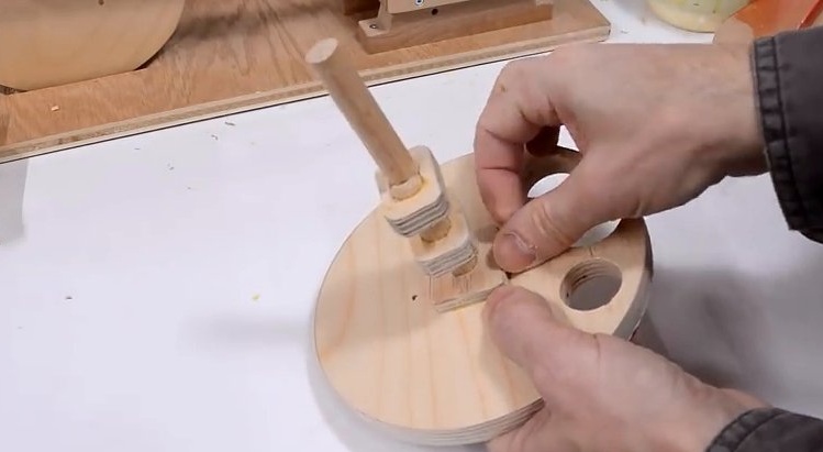
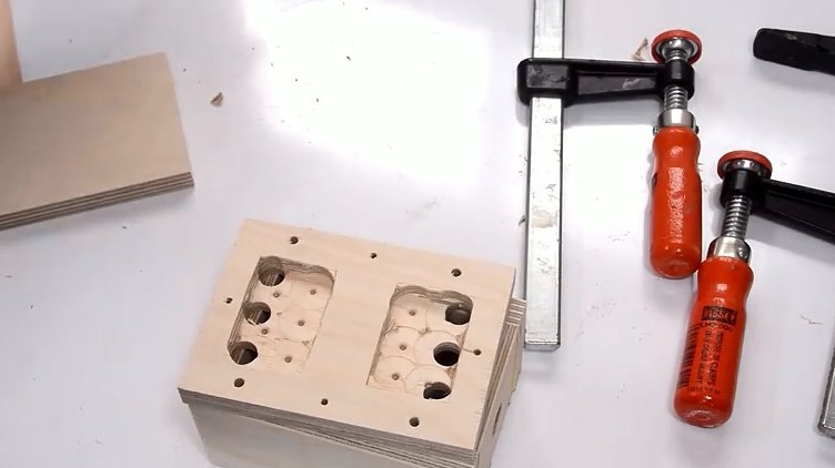
These photos show all the details of the piston block and valve. The two holes in the front of the plywood are the air inlet and outlet openings. By changing the inlet pipe, which blows (or sucks), the engine will work in the opposite direction.
All parts of the valve assembly are varnished. To make the product look evenly swollen, the master polished between the layers. It took a little grinding to make the valves slide easily.
The entire assembly is fastened with 19 mm wood screws with a diameter of 4 mm., A total of 38 screws.
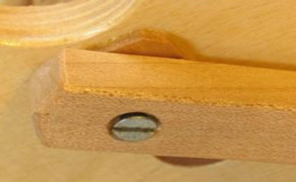
For mounting the bearing on the connecting rod, a cut-off self-tapping screw 38 mm long was used. The master had to cut off the end of the self-tapping screw so that he did not stick out on the other side of the flywheel too far. There was simply no other hardware available.
The piston end of the connecting rod is connected to the piston rod with a simple steel pin, which is made of a stubby nail. The hole in the piston rod is drilled a little less so that the finger fits snugly against the piston rod. The holes of the connecting rod are slightly enlarged, which allows the connecting rod to rotate freely on the pin.
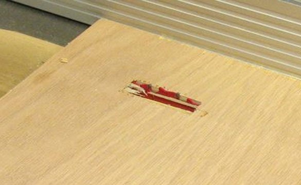
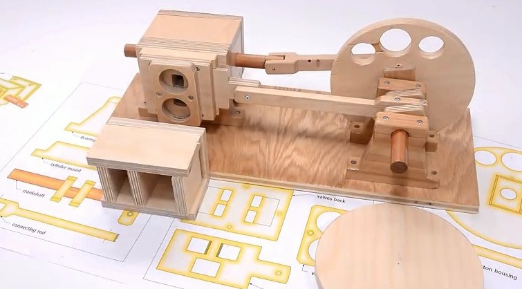
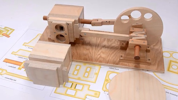
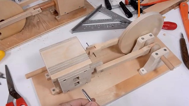
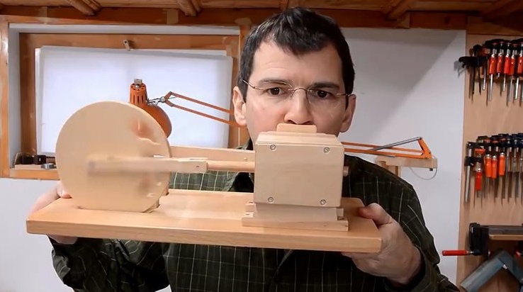
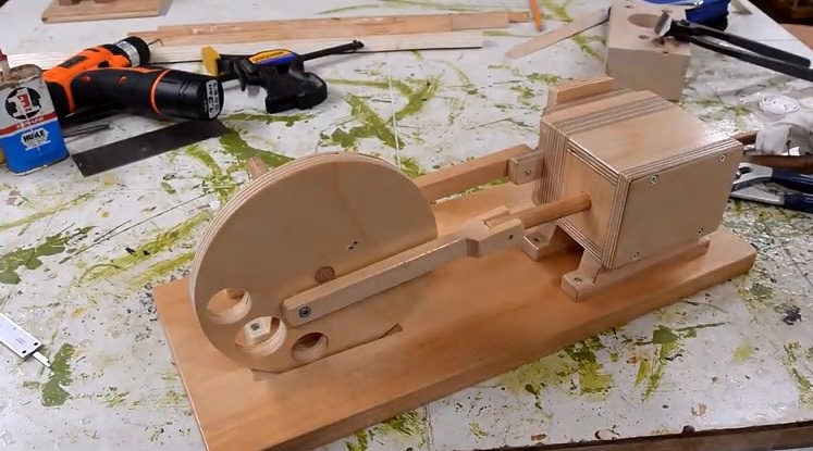
The entire engine is mounted on a piece of plywood.
For this engine, the master made a flywheel, as large as possible. Therefore, I had to cut a groove in the mounting plate so that it protrudes inward.
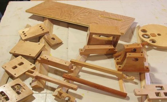
The master built the entire engine and made sure that it works smoothly, only then he painted all the details. The photo shows the drying of parts.
Engine varnishing required refinement to make the engine run normally again.
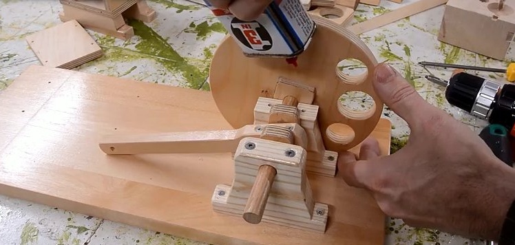
However, the varnish itself was not slippery enough, and in the end, so that the crankshaft would not creak, it was oiled.
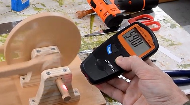
Check engine performance.
If you like homemade author, then try to repeat and make. Thank you for attention. See you soon!