» From sites » Specialist "Desulfator - a device for the" treatment "of batteries

Desulfator - a device for the "treatment" of batteries


An interesting device came across the Internet. Desulfator, according to the assurances of the master
"Capable of charging and desulfurizing / rejuvenating virtually any type of rechargeable battery, provided that the battery is not completely unrecoverable."

Honestly, I have not heard of such a device before, although there is a "discharge / charge" mode at the battery charging stations for army radio stations. I suspect that perhaps this is desulfation, although most likely this is due to the memory effect. I had to climb on the Internet and it turned out that some Soviet-made memory devices, in particular Vympel 55 and Vympel 27, had such an option. Such devices are sold on Ali, but the reviews vary. Some praise, some say "useless."

What is the essence of such a device? Desulfation is the purification of plates of the battery, from lead sulfate, using special cycles of charges and discharges. In short, working by a certain algorithm, the device helps to clean the plates from sulfates. And sulfation is the main reason for battery failure.

Another plus can be considered that the device is powered by batteries and for the desulfation process, you do not need to remove the batteries from the car. Some device models can simply be installed on car.

The disadvantages include the period of desulfation. It can be from 1 day to a month. But if the device is installed on a car, then there is no particular inconvenience.

Such devices can restore, according to some estimates, up to 85% of batteries, and this is a good result. Of course, if the plates are already destroyed, then you can no longer help them.

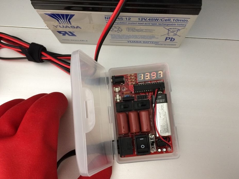
The desulfator, which we consider in this article, also serves as a charger. Unfortunately, the master did not provide a diagram and a link to the printed circuit board and microcontroller, but he promises to supplement the article in the future, and if the link is posted, then it will be in this article. And now, the article will describe in detail the process of mounting the board and the desulfurization process.

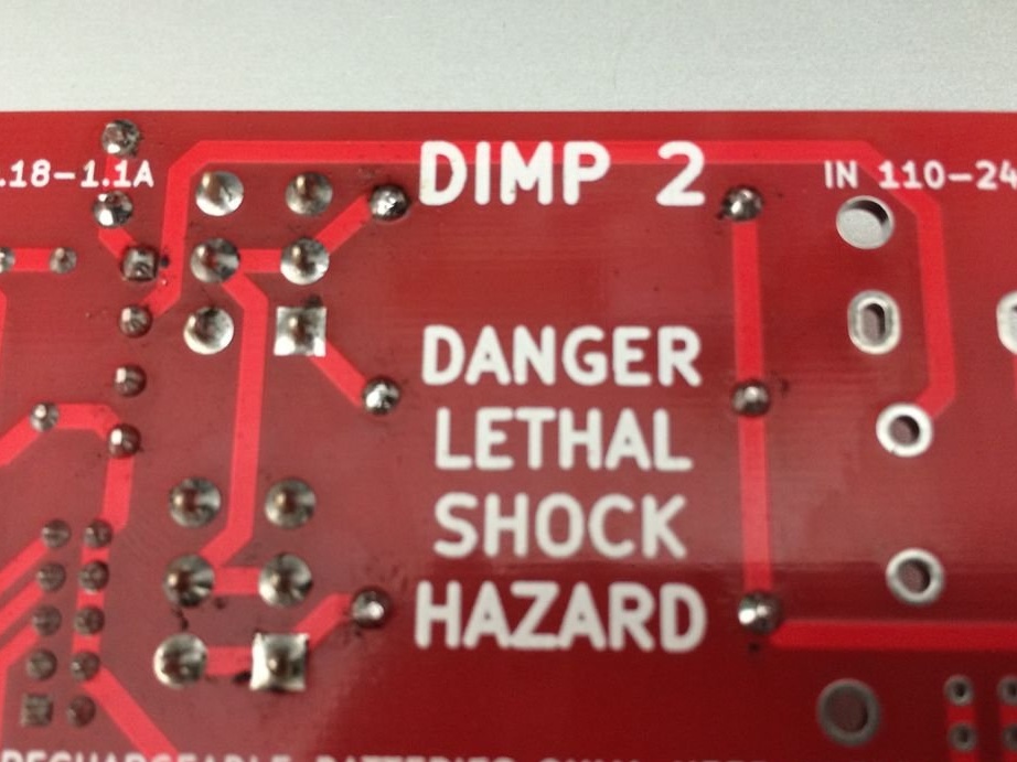
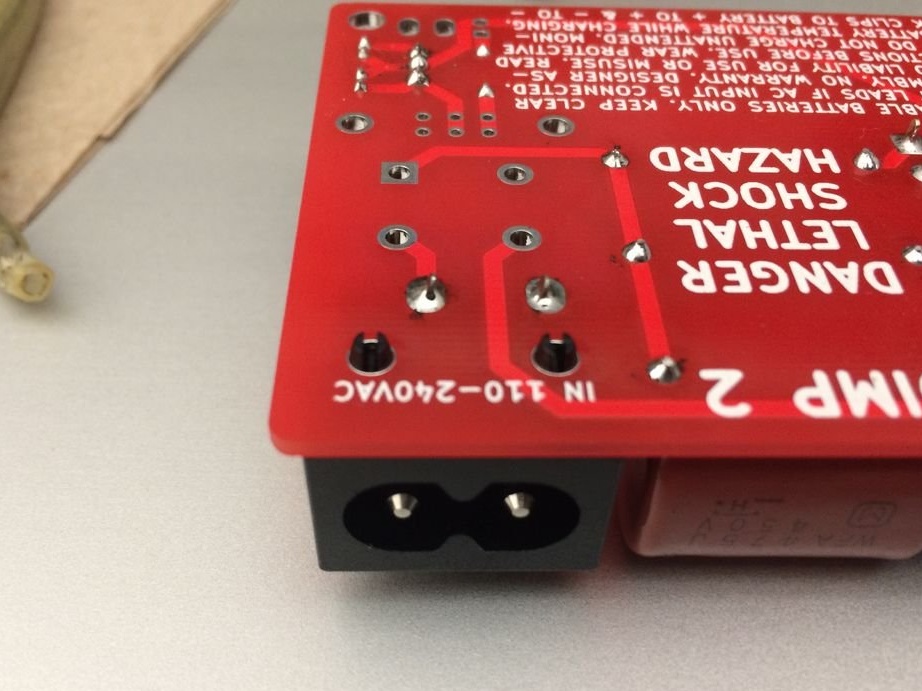
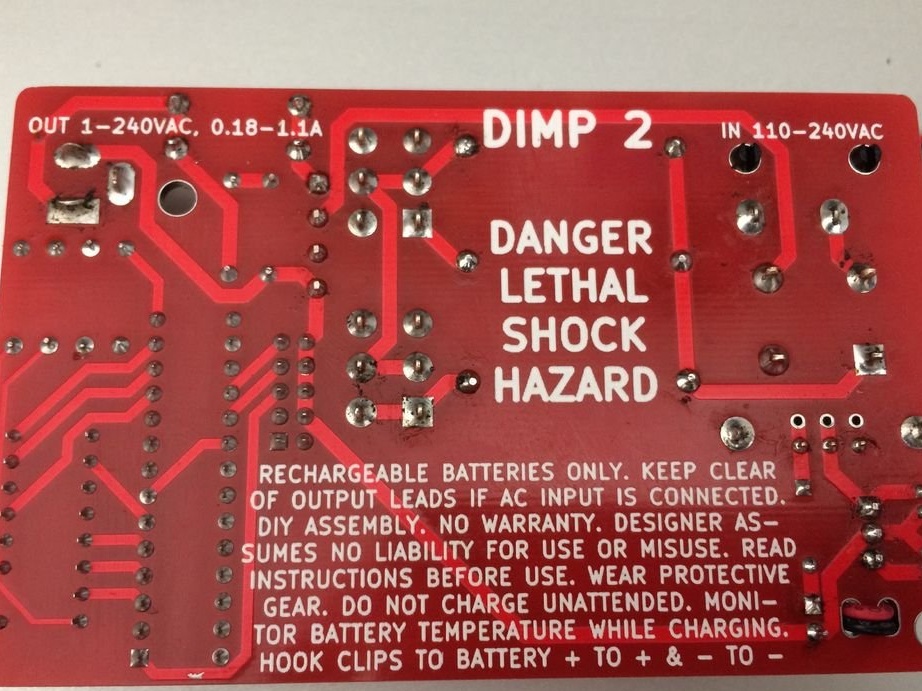
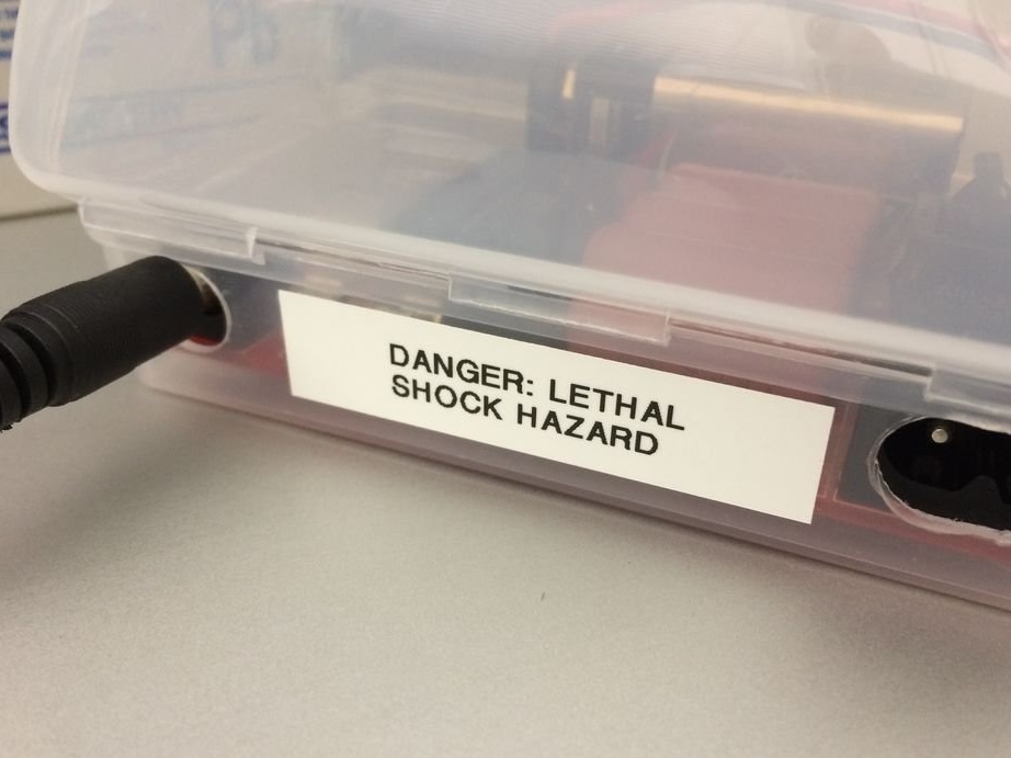
The master warns of a high risk of electric shock.

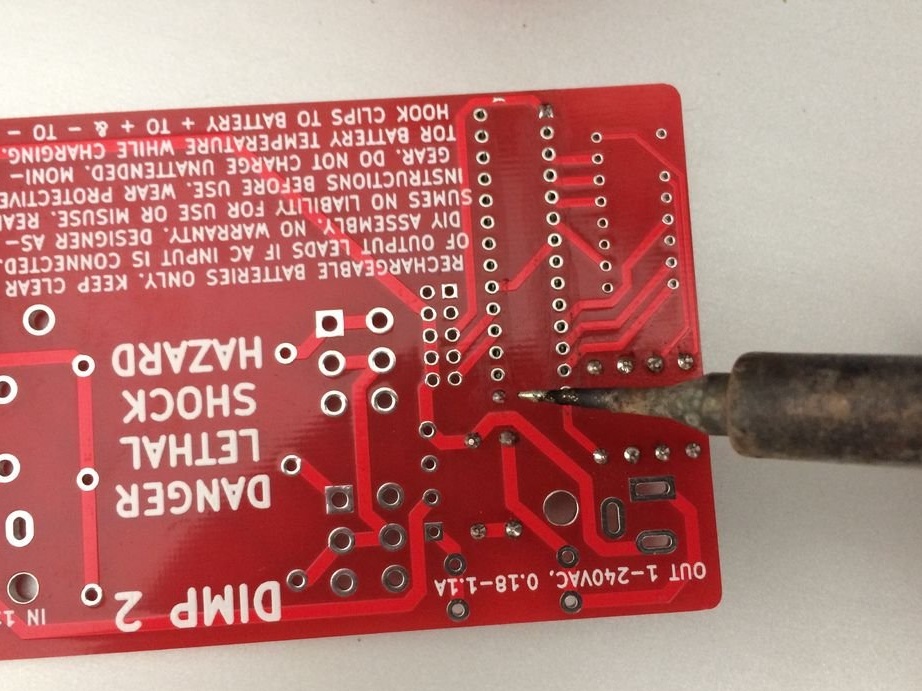
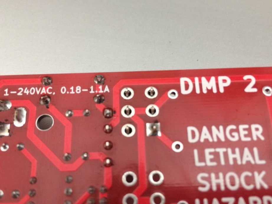
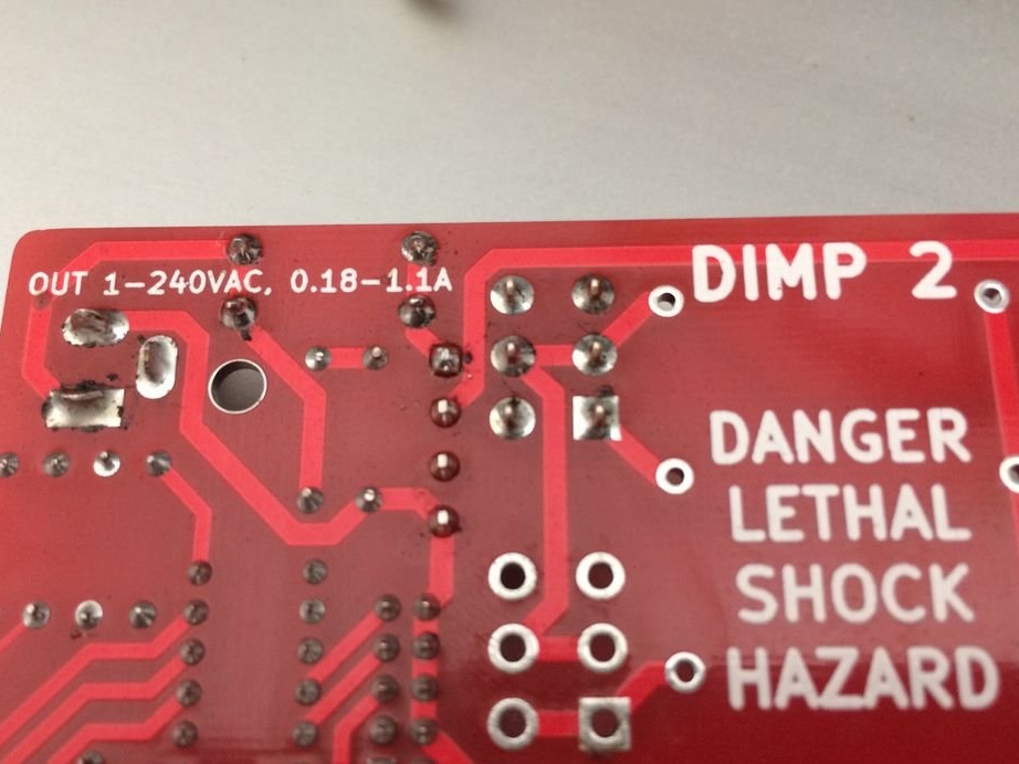
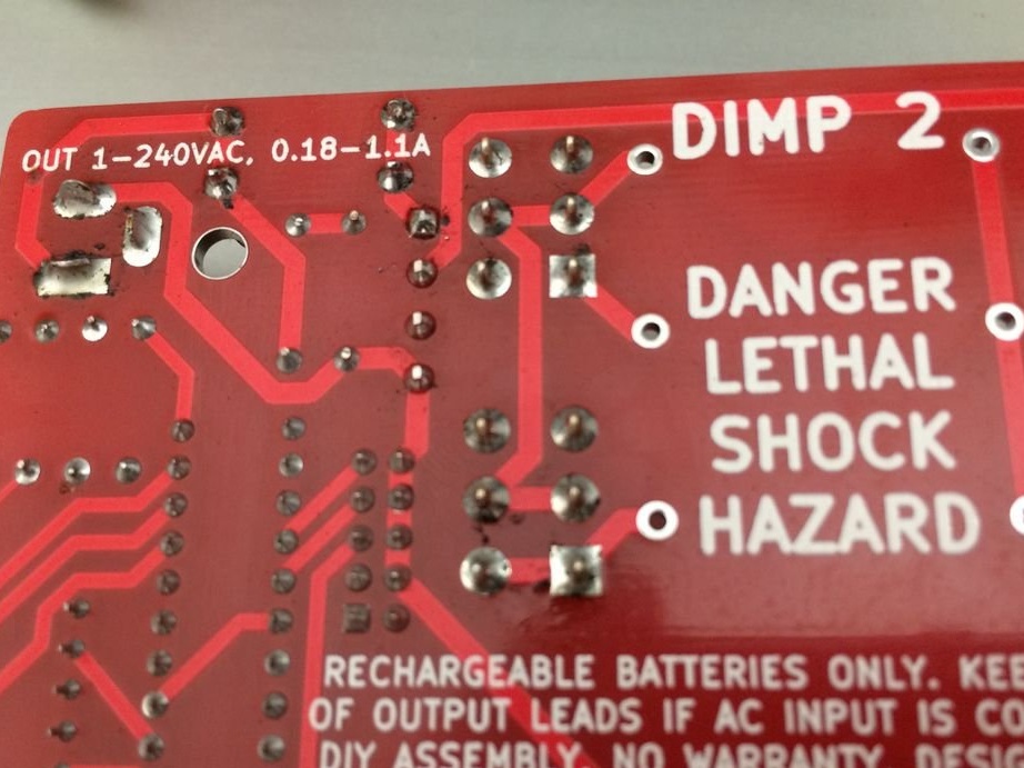
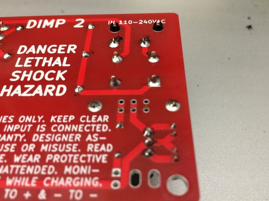
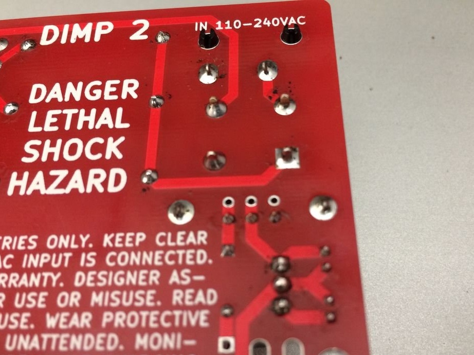
DANGER: DIMP 2 exposes the operator to lethal voltage through the output wires. Do not buy, create, or use DIMP 2 unless you are fully responsible for the safety of yourself and those around you.Only adults with the correct understanding of risks may attempt to use DIMP 2.

Tools and materials:
-List of electronic components;
- Wires for connecting to the battery (depending on the type of battery);
- soap box;
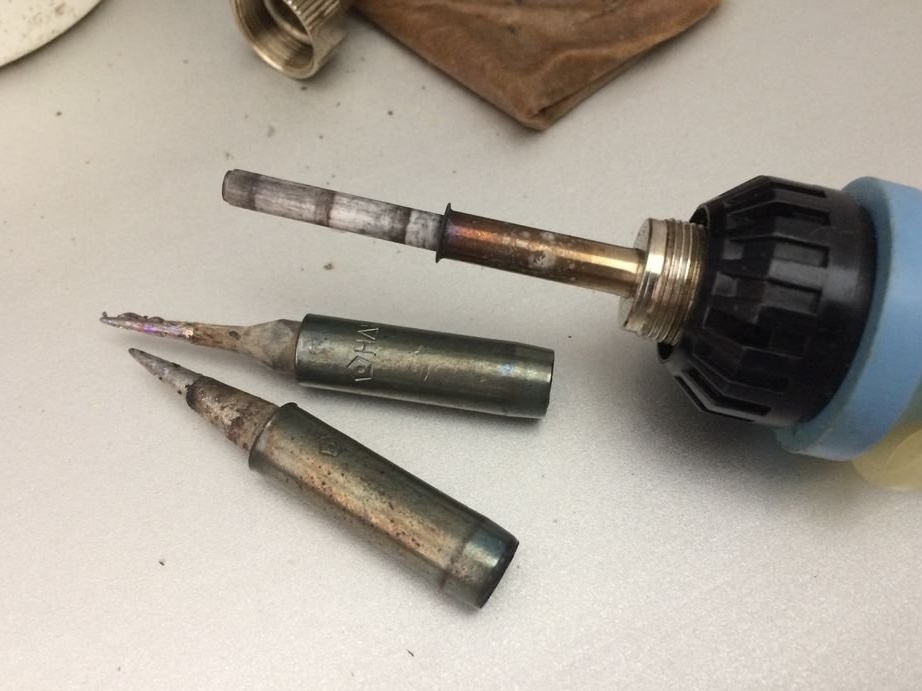
-Soldering accessories;
-Nippers;
Milling cutter;
-Knife;
-Scissors;


Step One: The Case
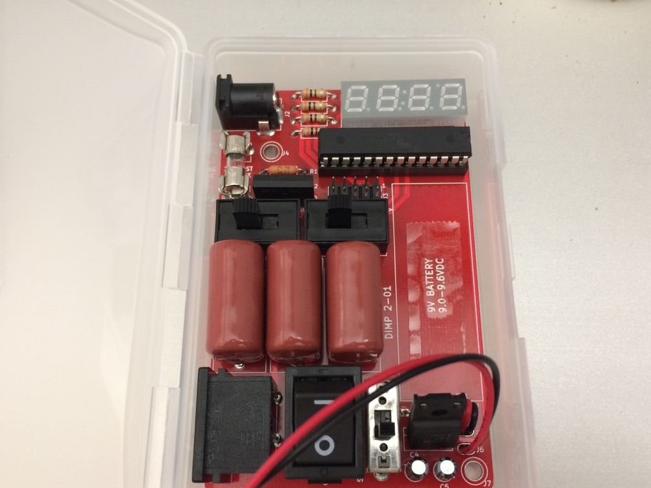
For the case, the master uses a soap dish with a lid. You need to check that the board fits freely in the case.

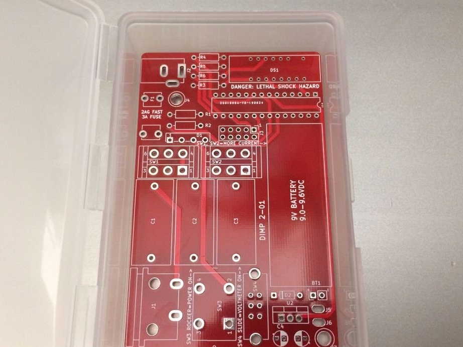
Step Two: Installing the Board
This is the biggest step.
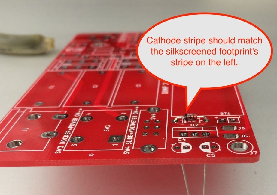
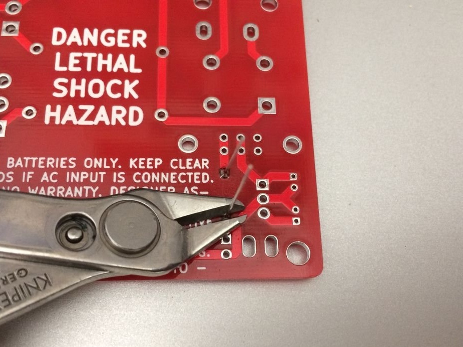
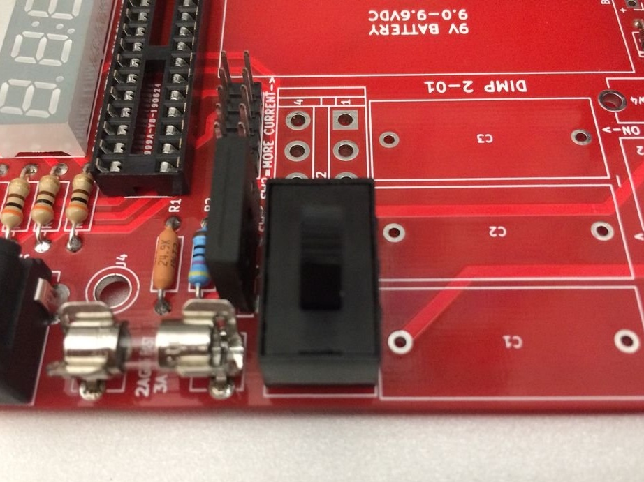
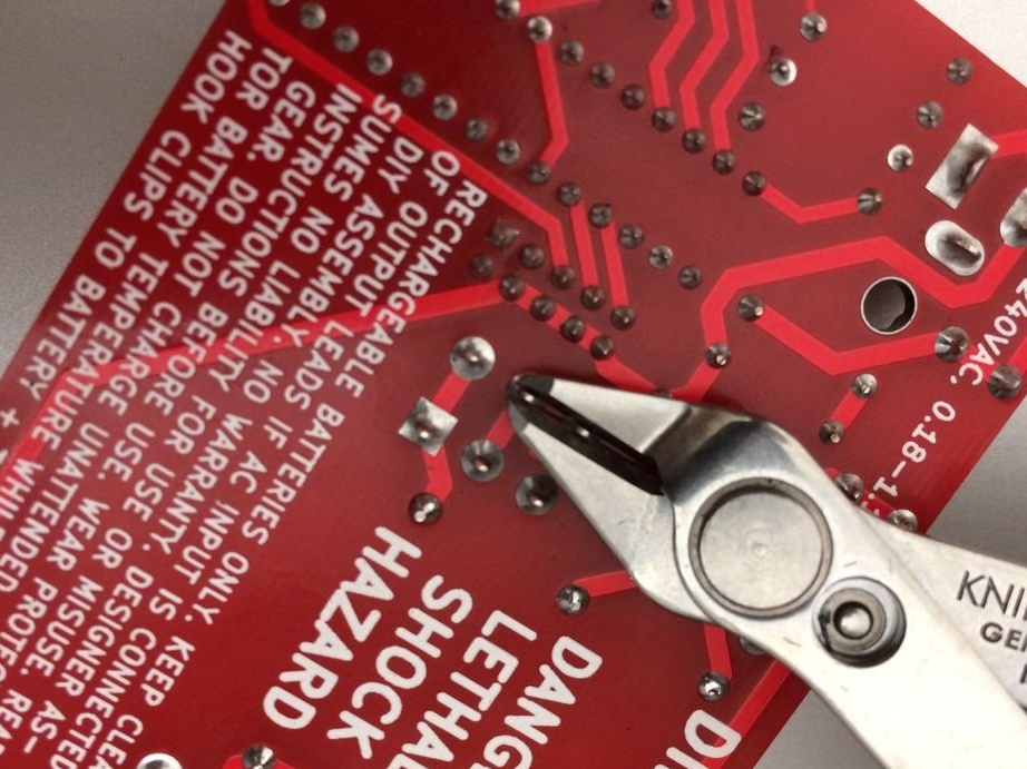
Mounts the diode on D2. Pay attention to the strip on the cathode end of the diode and insert it through the printed circuit board so that the strip is on the left, closer to the slide switch SW4. The non-striped end of the anode should be closer to the right edge of the board. Quickly solder the legs so as not to burn the diode, and cut off the protruding legs.


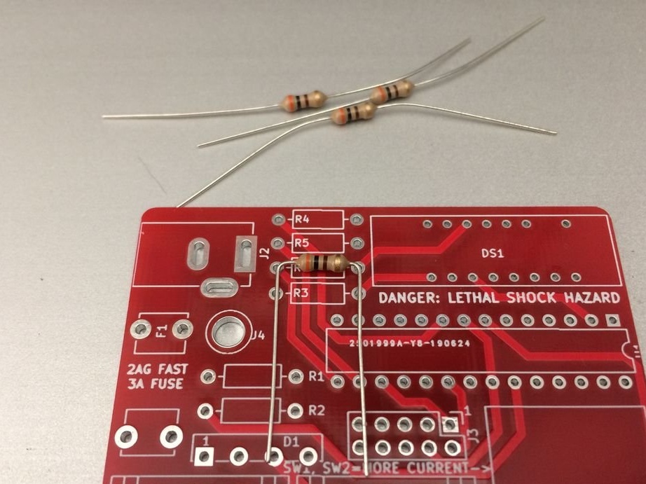
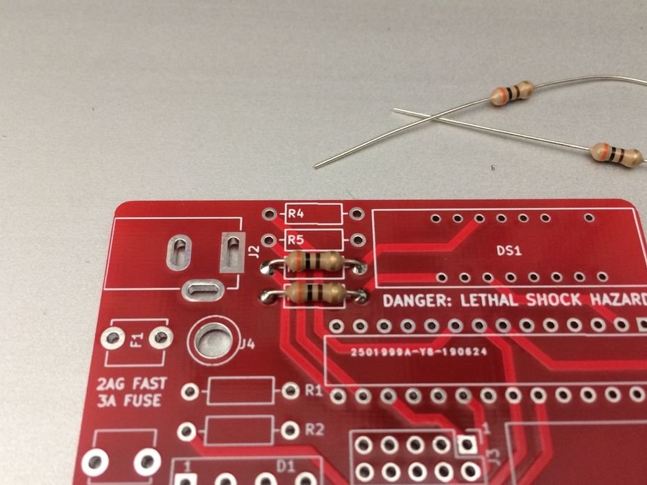
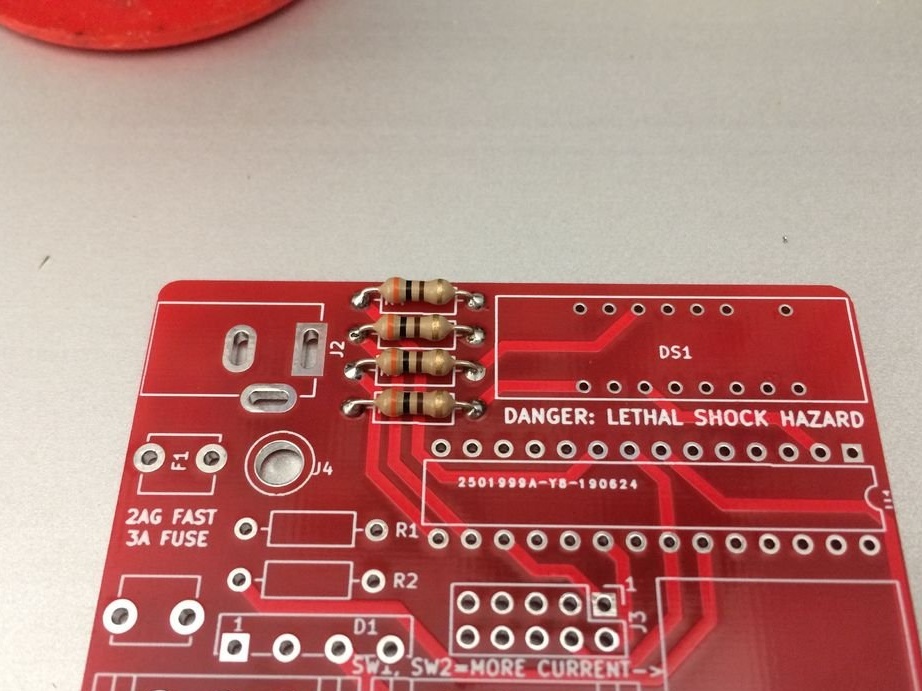
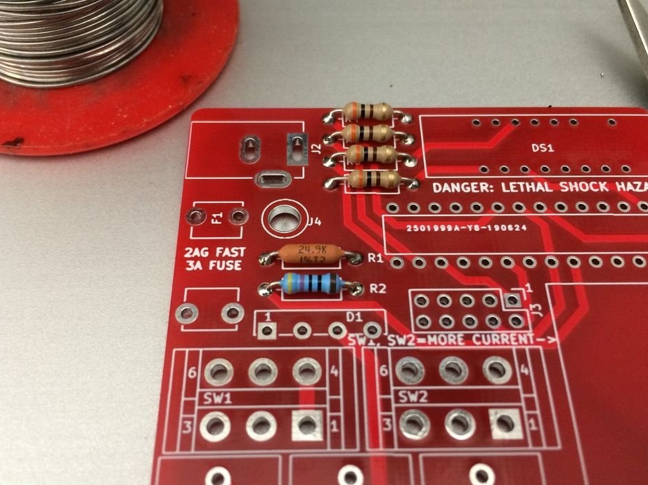
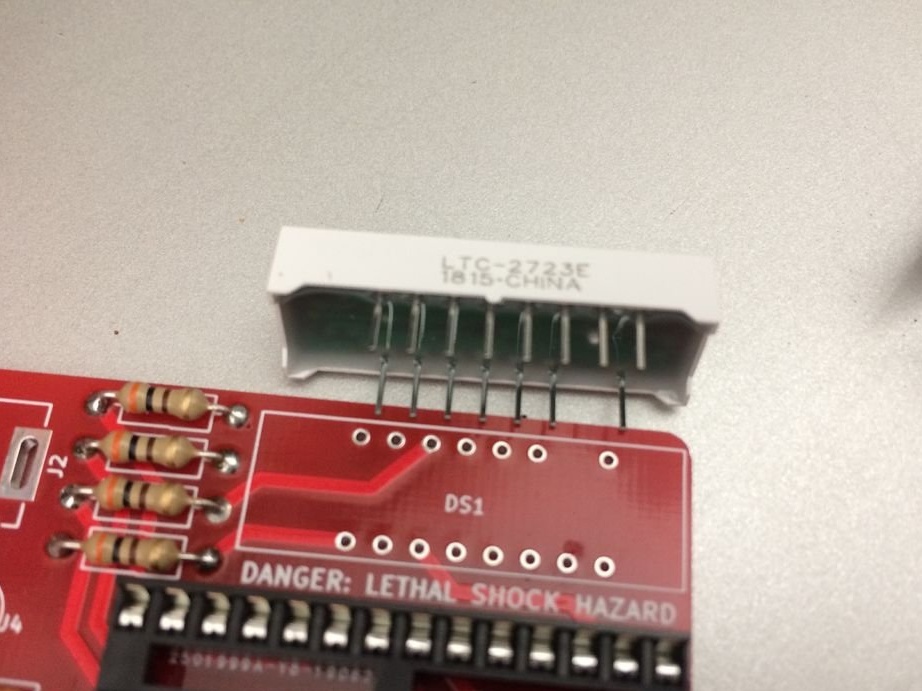
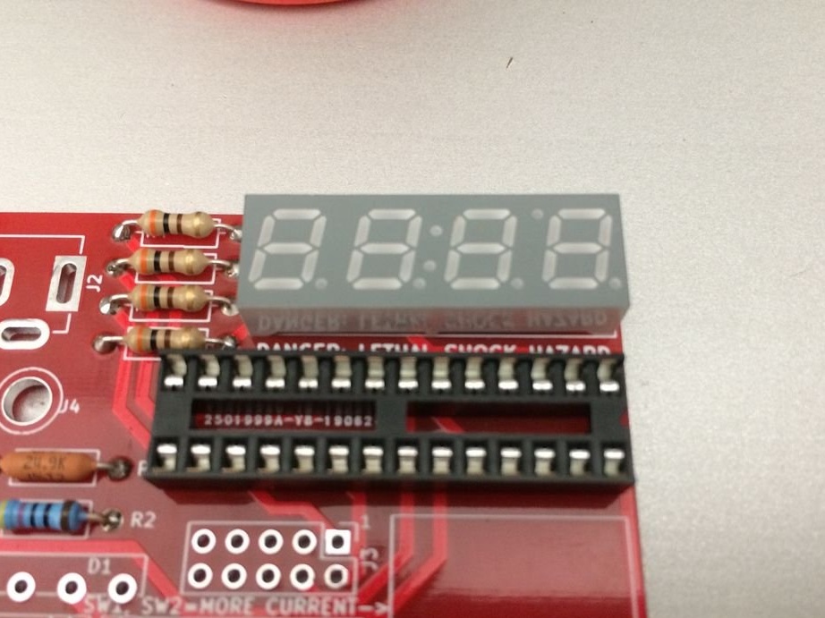
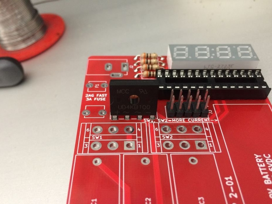
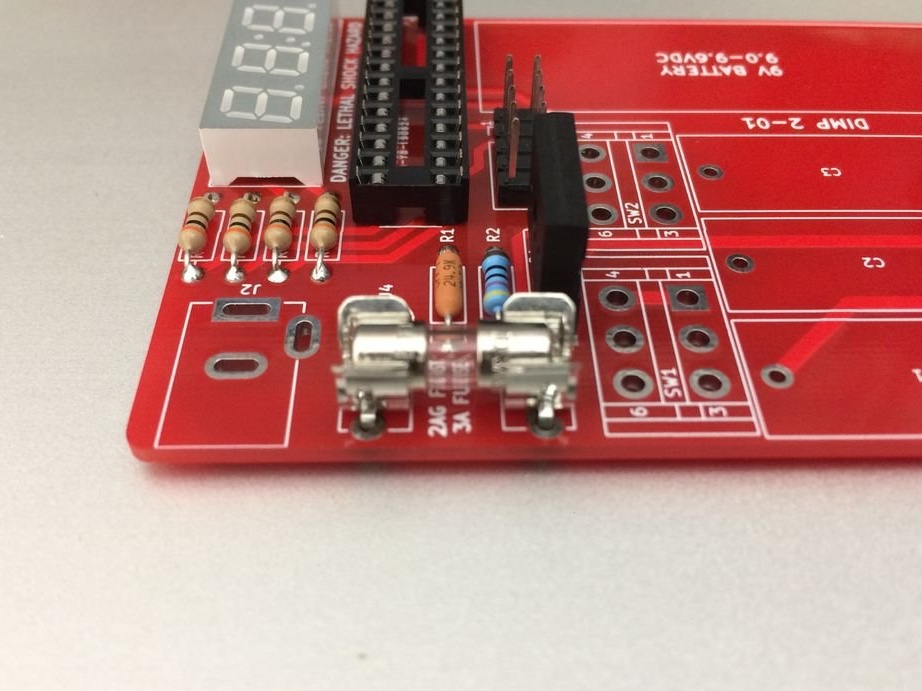
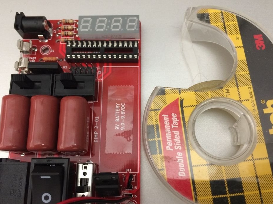
Solder four 300-ohm resistors for the LED display on R3, R4, R5, and R6. They are located together near the top edge of the circuit board.

A 300 ohm resistor has the following gradation = orange - black - brown OR orange - black - brown - gold


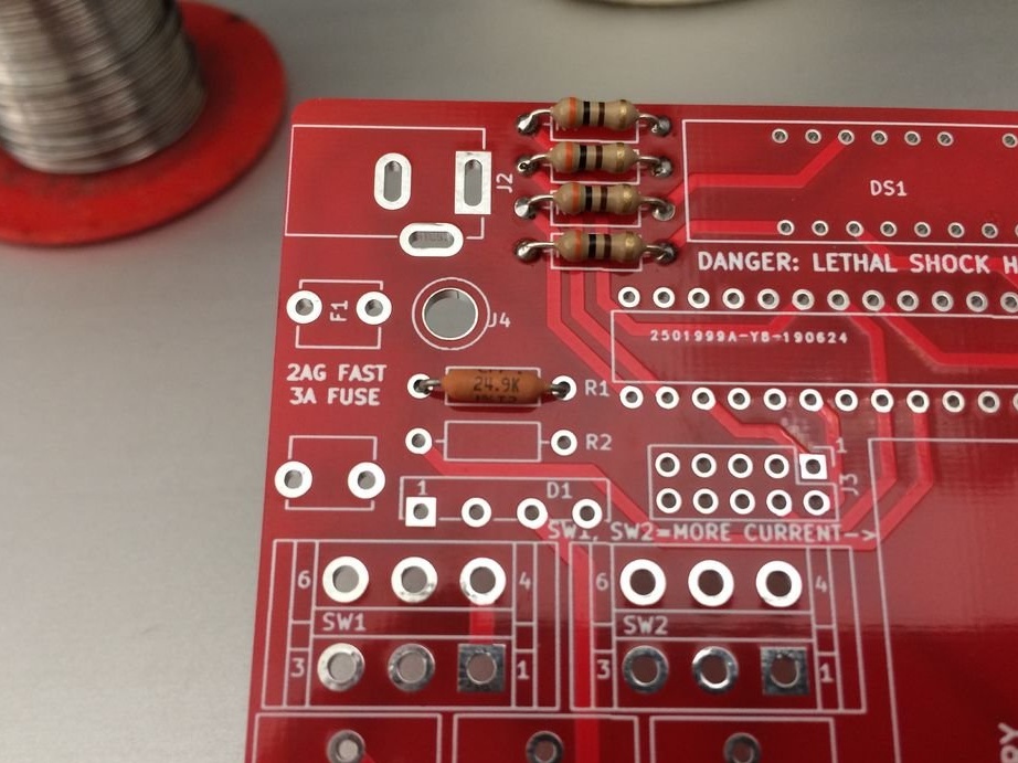
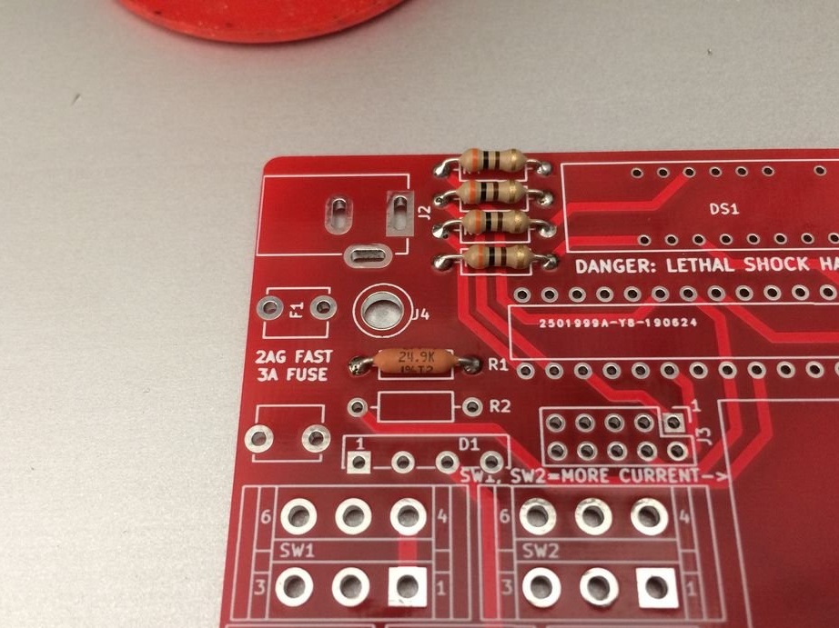
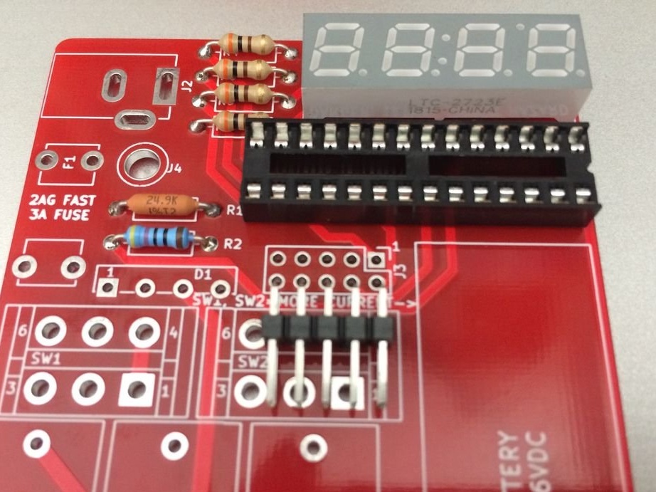
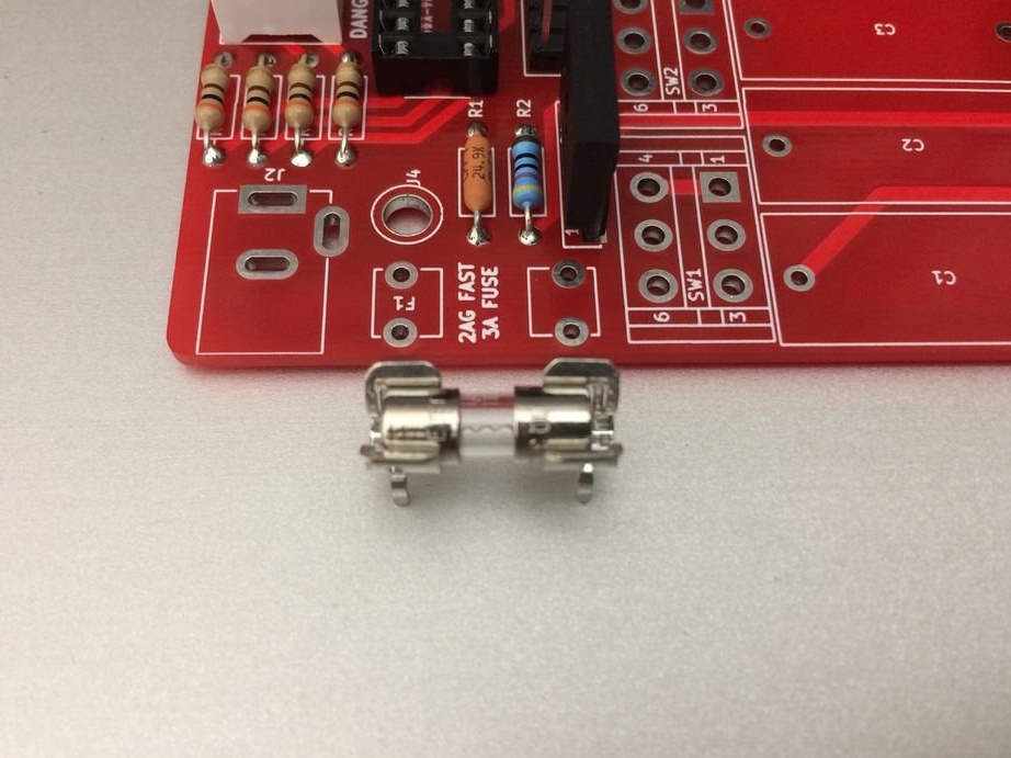
R1 and R2 - voltage divider for a voltmeter.
R1 is 24.9 kOhm and R2 is 470 kOhm. Use a multimeter to check their rating.
R1 = 24.9 thousand. 1% = red - yellow - white - red - brown
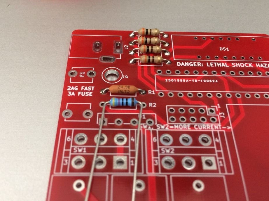
R2 = 470 ohms 1% = yellow - purple - brown - brown OR yellow - purple - black - black - brown
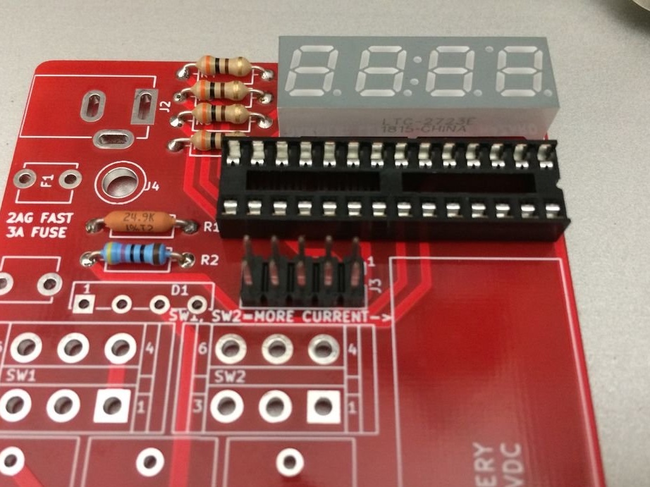
Solder them to the appropriate places, which are located near the upper left side of the circuit board and are designated R1 and R2.


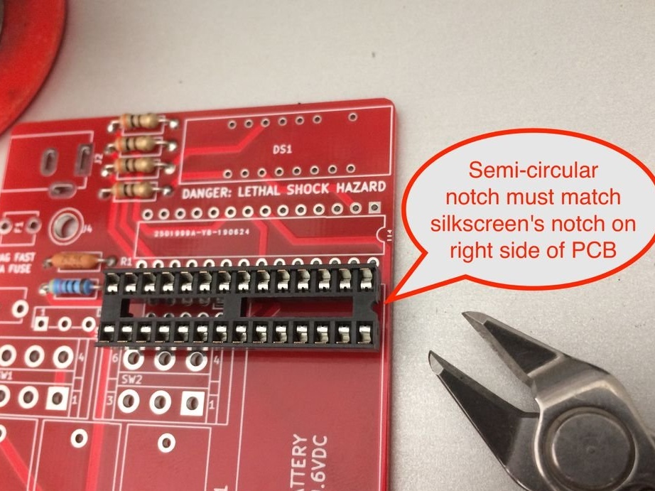
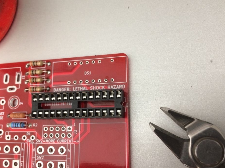
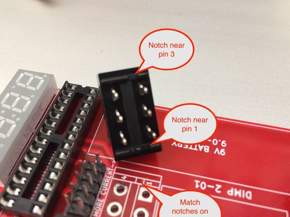
Next, you need to solder the DIP socket.
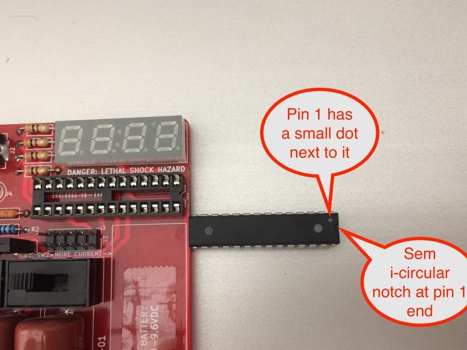
Make sure you find pin 1 on the DIP connector. A semicircular recess indicating pin 1 should be located on the right edge of the board. This is important, so double check it before soldering.

Install the socket and solder the legs 1 and 15 first, and then all the others.


Mounts LED display. It is located in the upper right corner of the board and can be installed in only one way due to the lack of a hole for contact 10.
Solder feet 1 and 9 first. Check that the display is correctly positioned. Solder the rest of the legs.


If you want to flash DIMP 2 yourself, then install J3.


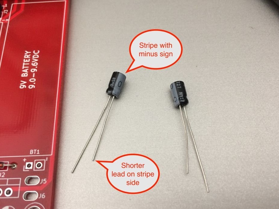
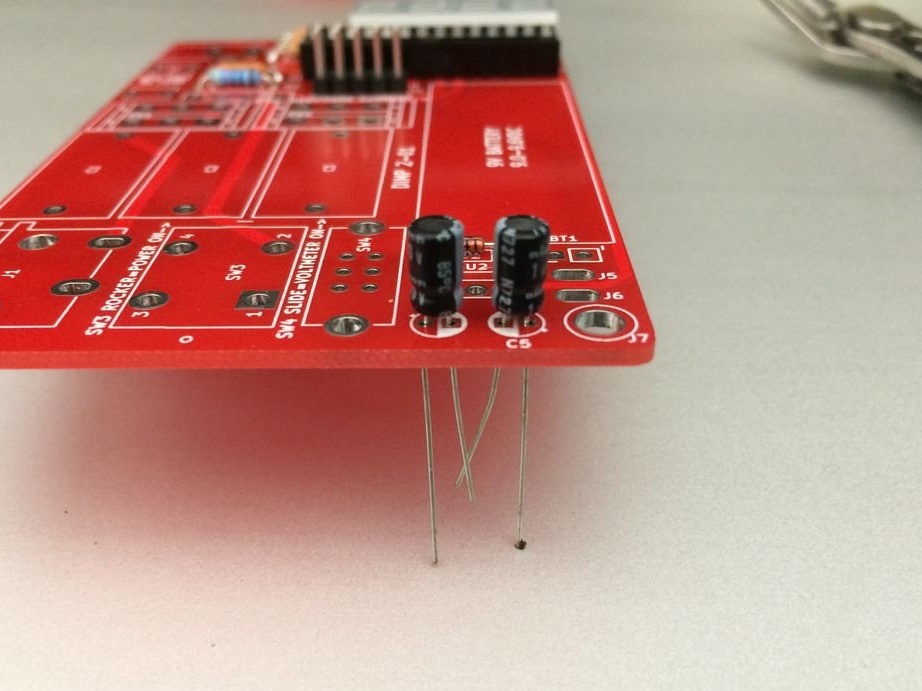
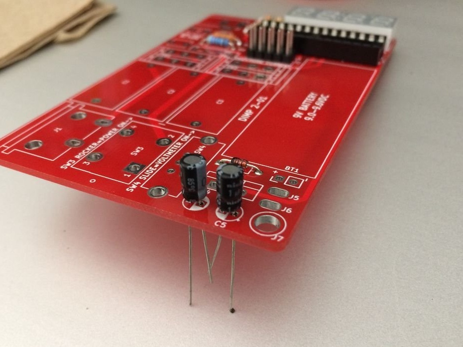
Look at the markings on each capacitor and find the negative / negative strip on one side. This side should also have a shorter leg.

Then look at the mounting location of C4 and C5. Each of them is a circle, half of which is painted in solid white. This half is for the negative contact of the capacitor.


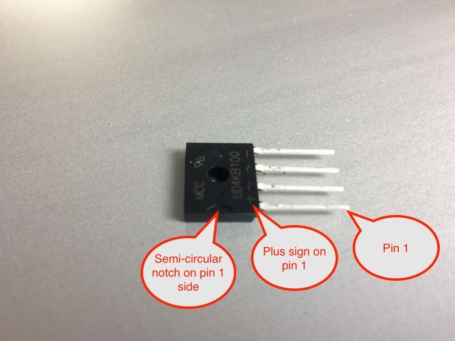
Observe precautions against electrostatic discharge with a diode bridge.
Locate pin 1 of the diode bridge. A tiny + (plus) sign should be engraved above it. If the sign is missing, then look at the case. Above pin 1 there should be a semicircular recess.


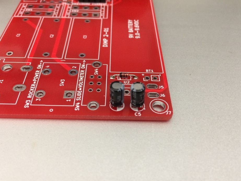
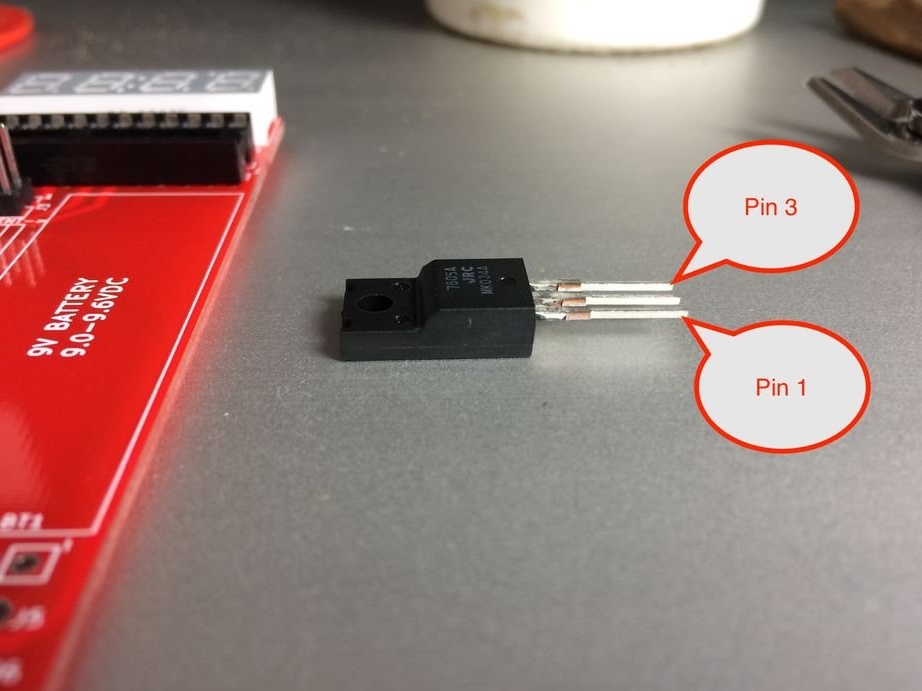
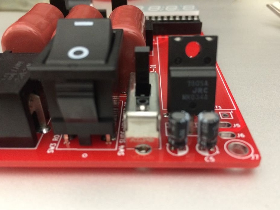
If you turn the voltage regulator with the text toward you, then the leg on the left will be 1. The regulator is installed on the contact pad U2 with the text to the capacitors C4 and C5.


Solder the fuse holder.


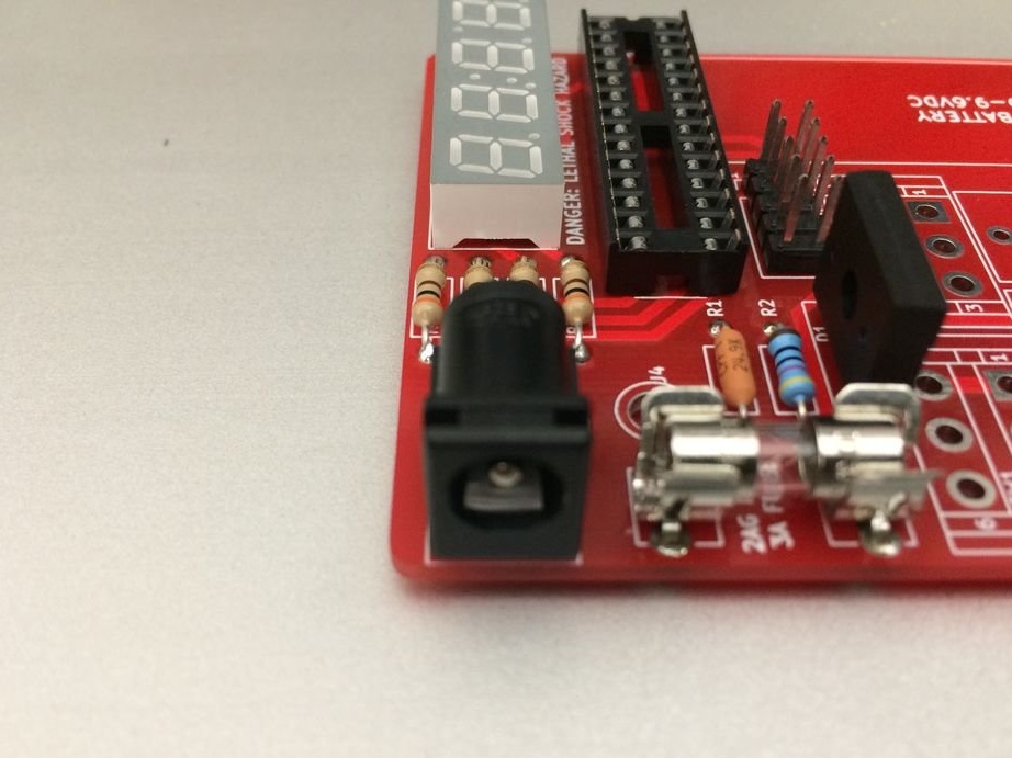
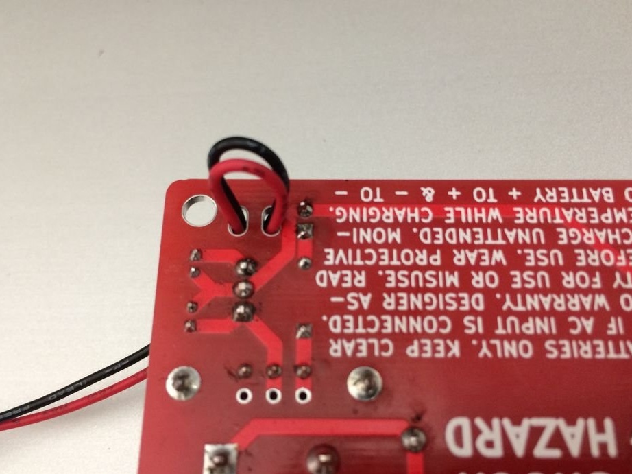
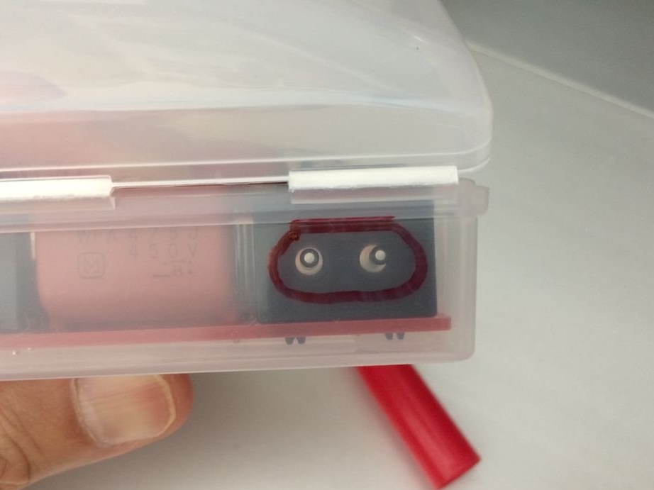
Mounts the connector. The wires from this connector will go to the battery.

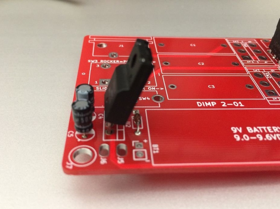
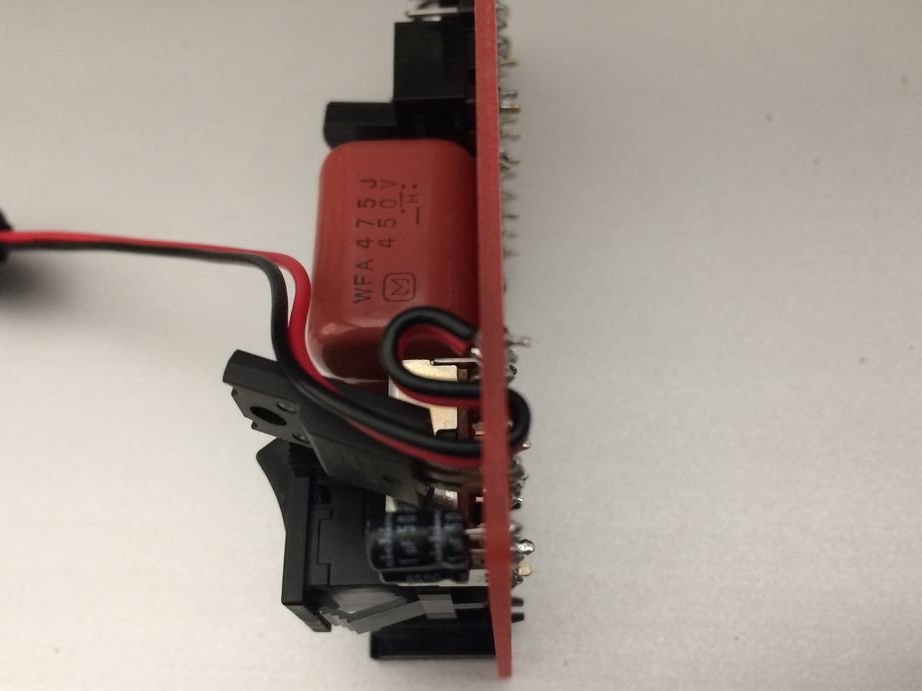
Solder two slide switches.


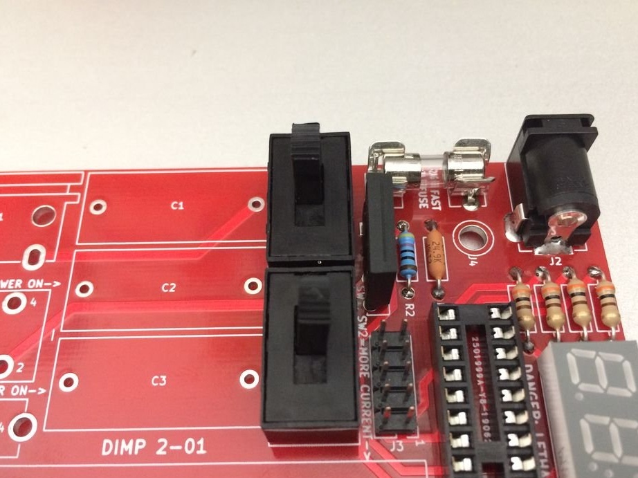
Capacitors C1, C2 and C3 do not have polarity and can be soldered on either side.


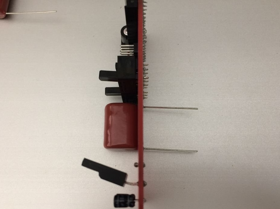
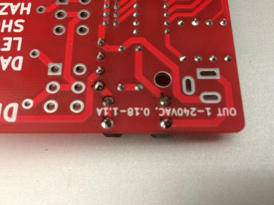
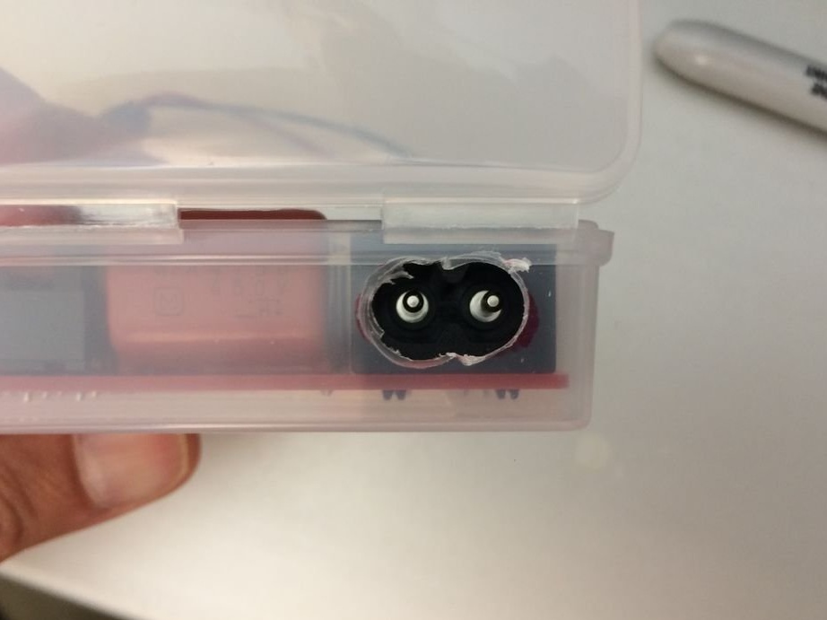
Since the AC power input is designed to be installed on printed circuit boards with a thickness of 1.4 mm, the latches do not snap on this circuit board, 1.6 mm thick.

Take a little hot glue, apply it only to the plastic latches at the entrance (not to the soldered pins), then quickly insert the entrance into the holes and press it close to the circuit board. If you don’t have hot glue, glue it on super glue. Let the glue dry, then solder the two pins.

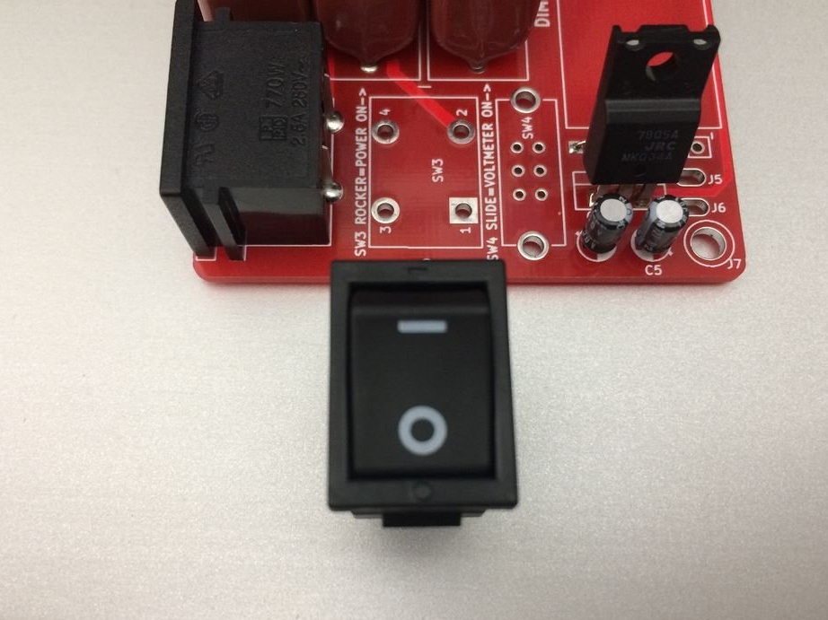
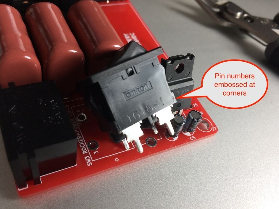
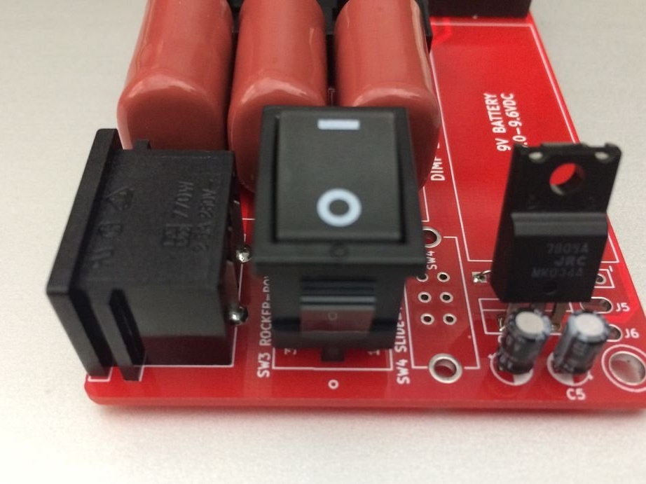
Look at the marking of the SW3 key switch. The marking |, on the switch, should be closer to capacitors C1, C2 and C3. Marking 0 (off) should be closer to the edge of the board.


The SW4 slide switch has three tiny pins and two large metal mounting pins. You will need to first solder the mounting pins.

Set the switch to the pad. Solder the two mounting pins.


Now you can solder the contacts.

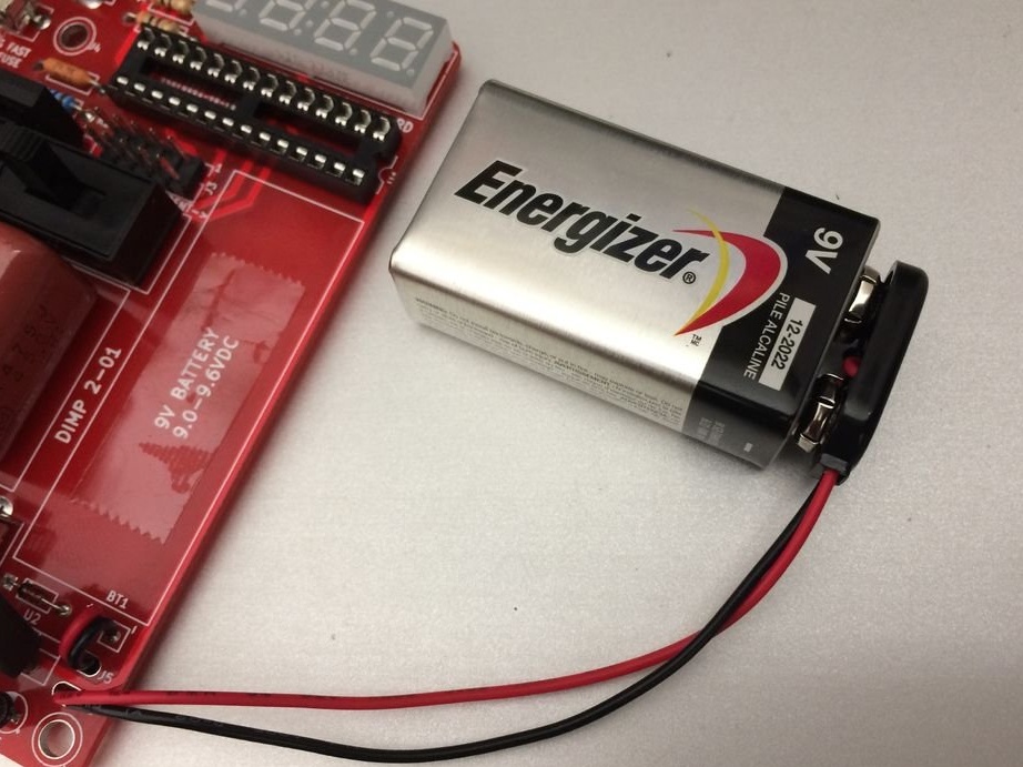
Next, install and solder two wires from a 9V battery.


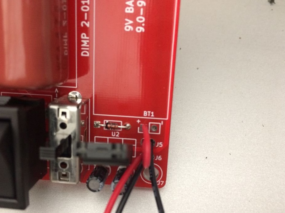
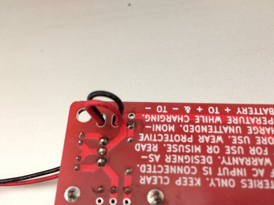
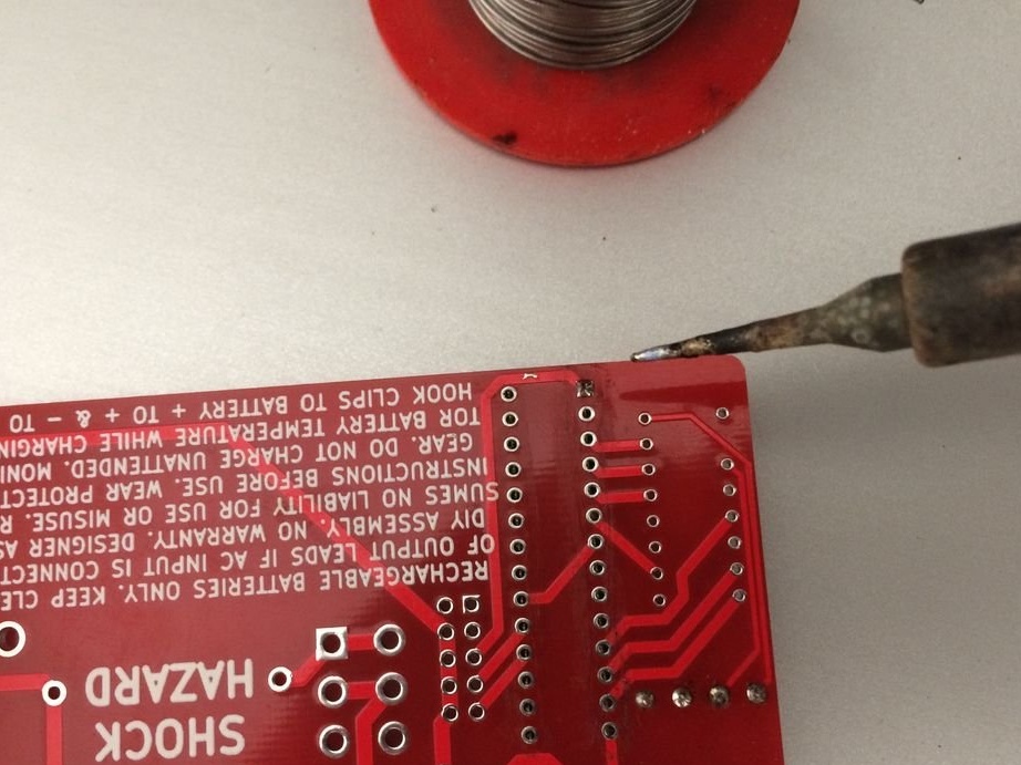
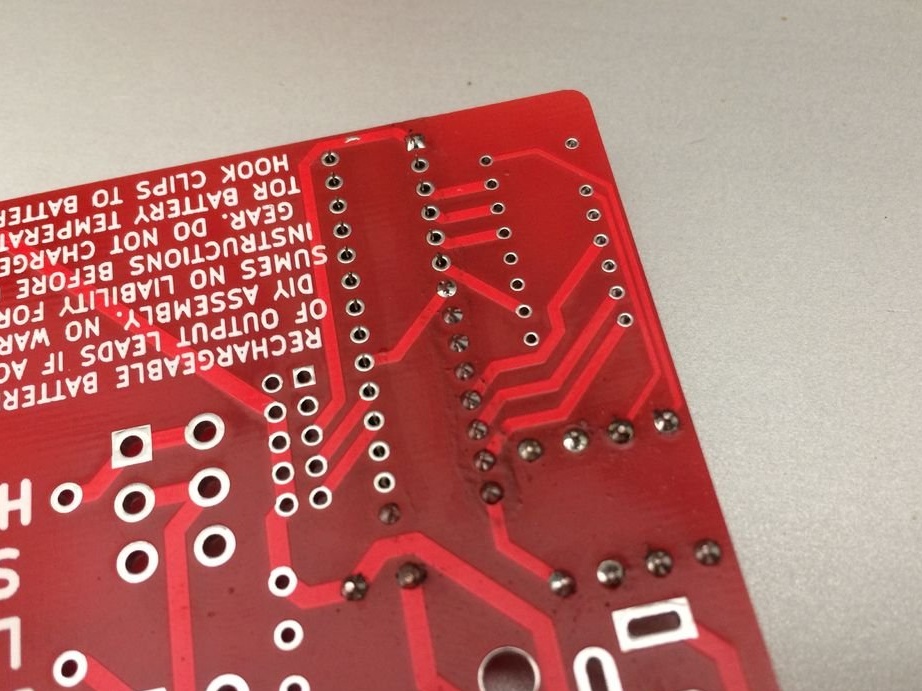
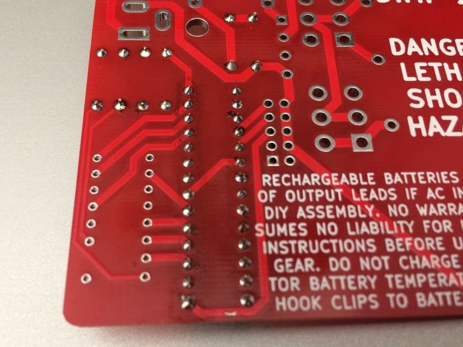
Soldering completed.Do not forget to remove flux residues.

Step Three: Connect, Verify
IMPORTANT: turn off SW4.
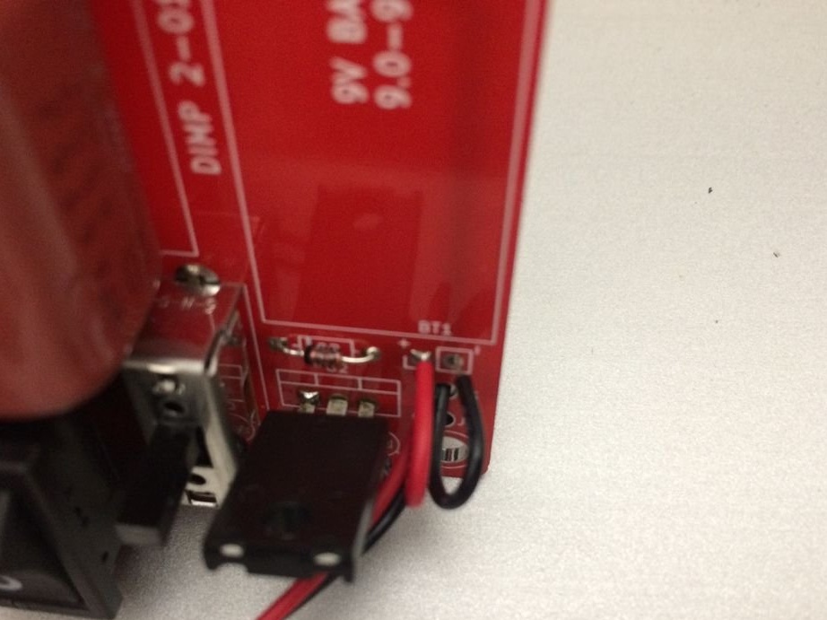
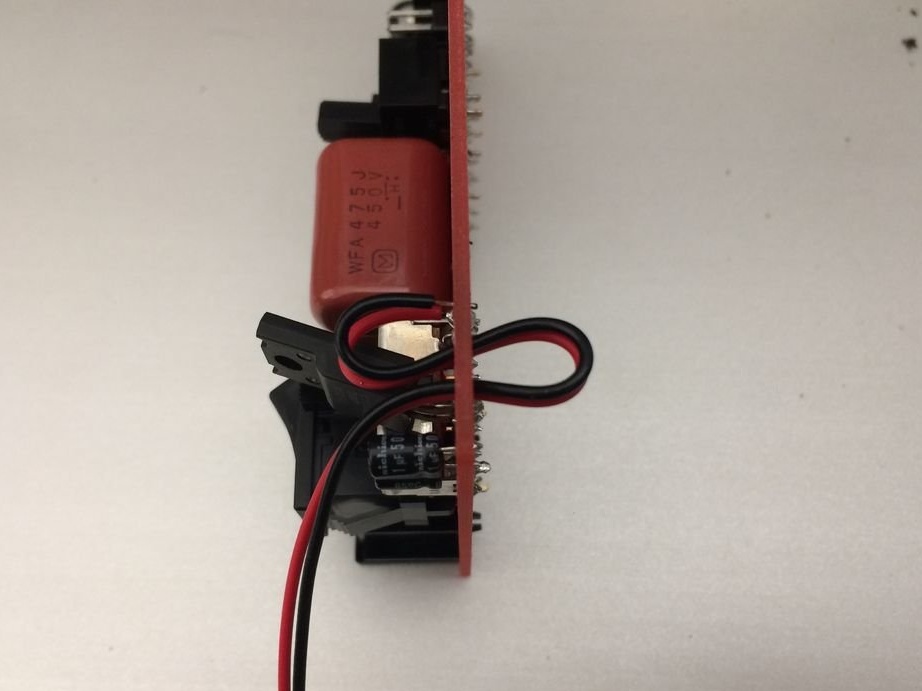
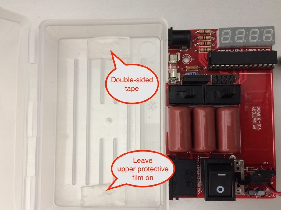
Connect the battery to the connector. Glue double-sided tape to the pad.


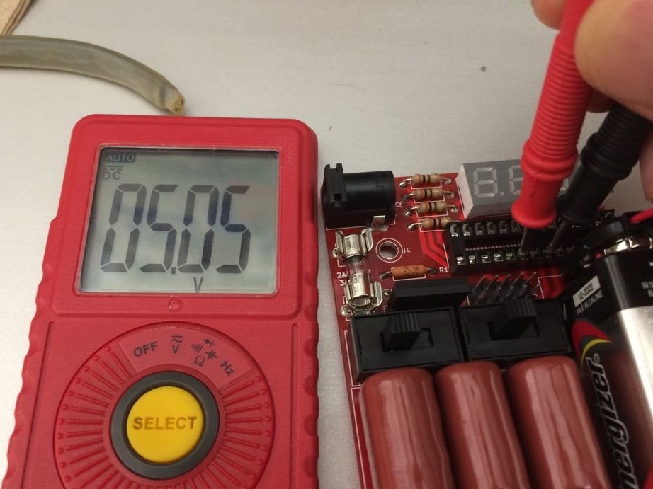
Before installing the ATMEGA48V-10PU in the DIP connector, you need to check that the line voltage regulator supplies 5 V to the Vcc pin. SW4 must be turned off (the drive is shifted down to the bottom edge of the board).

Install the multimeter in voltmeter mode and install the test probes on pin 20 (Vcc) and pin 22 (GND). Pin 20 is the sixth pin from the lower left corner of the DIP socket.

Set switch SW4 to the on position. The voltage should be 5.05 V, with a new 9 V battery.
After checking, turn off SW4 and remove the 9 V battery from the holder.

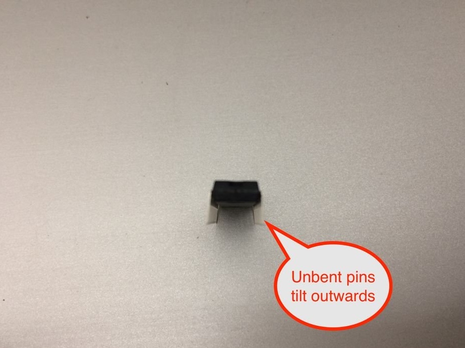
ATMEGA48V-10PU can be supplied with pre-bent contacts or not.

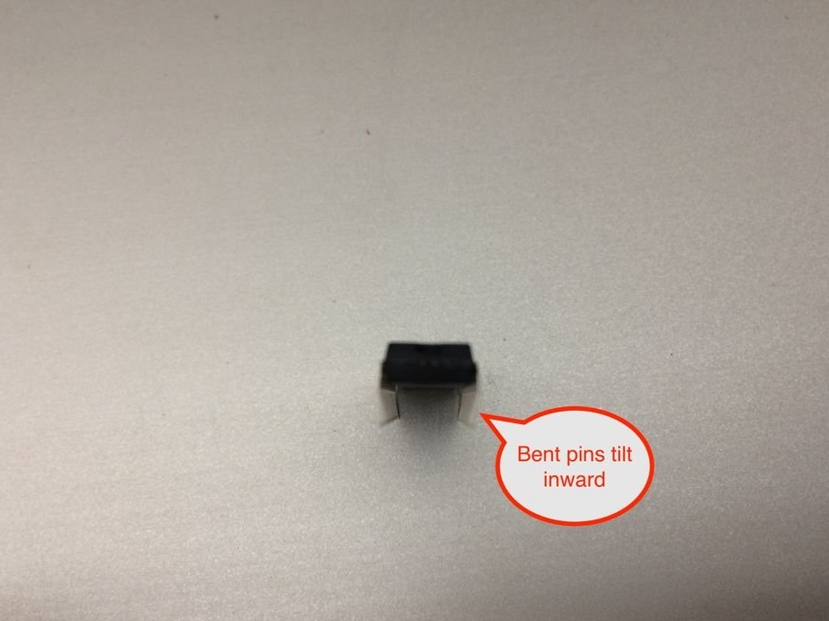
Look at them and see if they are straight. If the legs are not bent in advance, very carefully bend both sides slightly inward. This can be done by resting the legs on a hard surface, such as a countertop, and pushing.

Then find a tiny dot that points to pin 1 or a semicircular notch in the upper part of the microcircuit, and orient it towards the end of the DIP socket with a semicircular notch cut out.

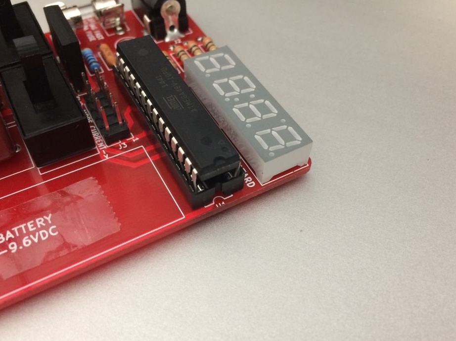
Gently push the chip into the slot, applying even pressure to the entire chip so as not to break.


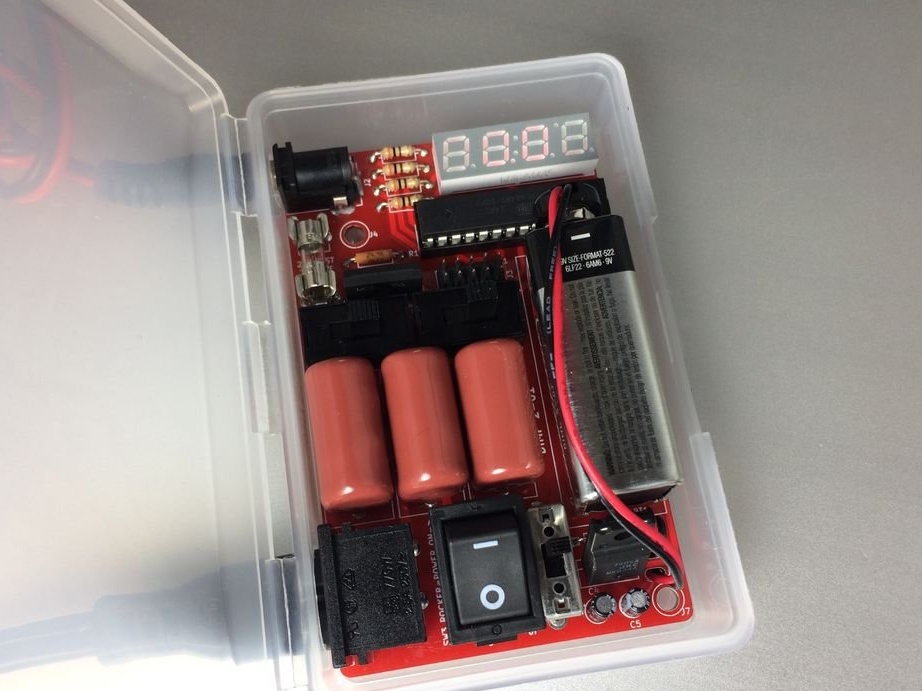
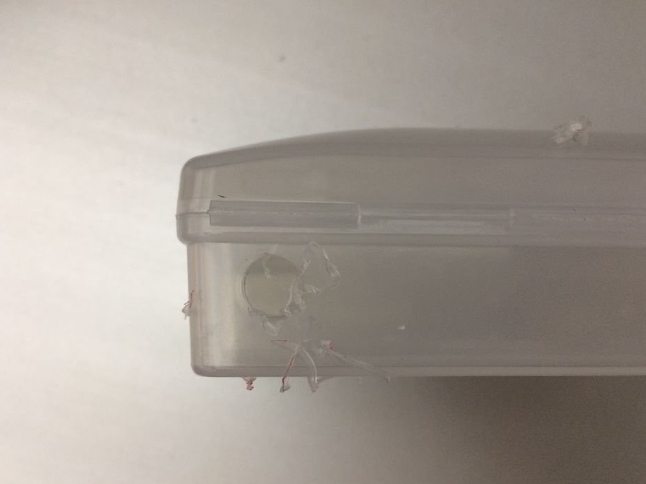
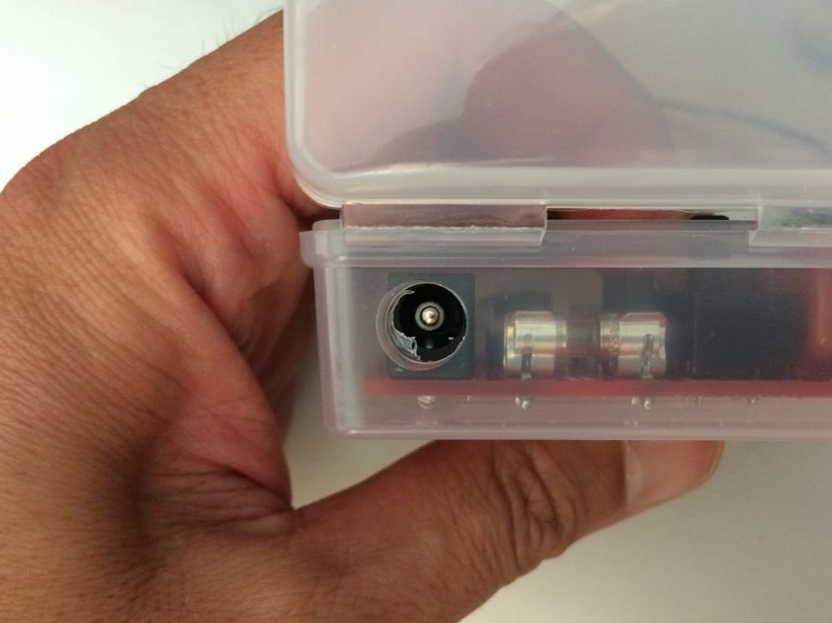
Step Four: Installing the Device in a Case
Cut the leads from the slide switches SW1 and SW2.

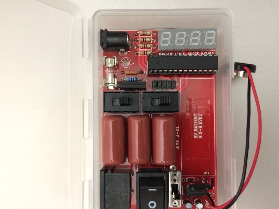
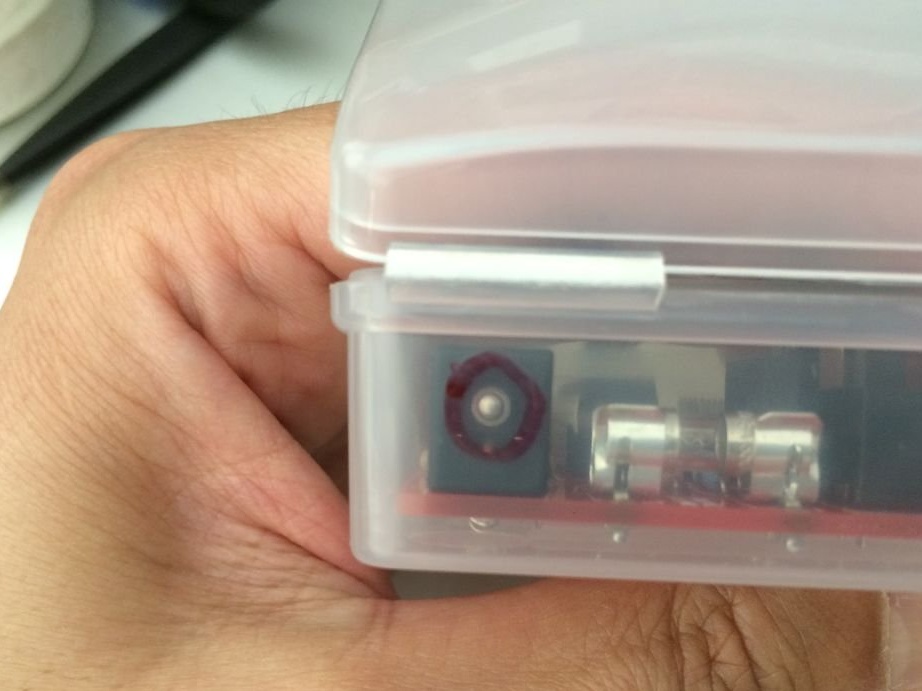
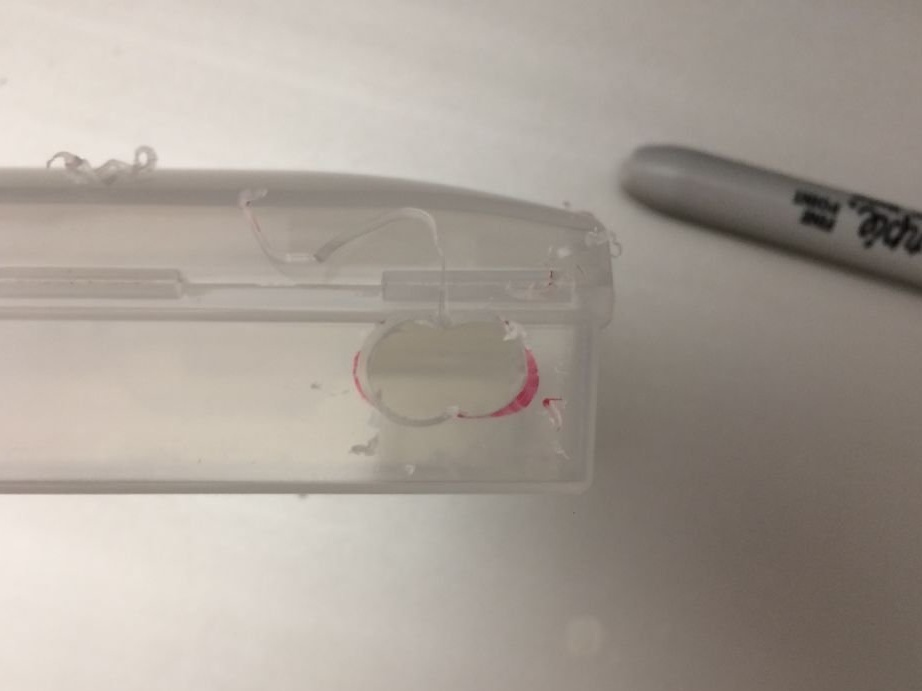
Installs the board in the case and marks the places for connectors. Then it cuts out the holes for them and sticks the board on a double-sided tape.


Step Five: Checking the Circuit
Check voltmeter circuit.
Make sure the circuit board is in a safe place and the AC power cord is not connected to DIMP 2. Make sure the SW3 toggle switch is off (0). Make sure the fuse is installed.

Turn on SW4. You should immediately see 000.0 on the LED display.
Turn off SW4.
On the battery, check the voltage with a multimeter.

Connect the wires to J2, then attach the clamps to the battery, observing the polarity.
Turn on SW4. The display should have a voltage equal to the previously checked multimeter.

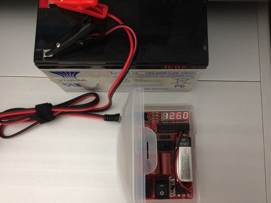
Since you do not know who can use DIMP 2 in the future, be sure to make or buy at least one warning sticker: Danger of electric shock.

Step Six: Desulfurization
DANGER: This step includes testing for deadly high voltages.

IMPORTANT: Always wear protective equipment.
Place the DIMP 2 and the battery on a fireproof, non-conductive, stable surface.

MAKE SURE THE AC CABLE IS NOT CONNECTED.

Set the two sliders according to the current required to charge the battery. For the smallest current (for AA batteries), slide both switches to the left (with DIMP 2 orientation so that the LED display is in the upper right corner). To increase the current to medium, slide one of the two switches to the right. To maximize current (for most power tool and car batteries), slide both switches to the right. As a rule, it is better to use less current.

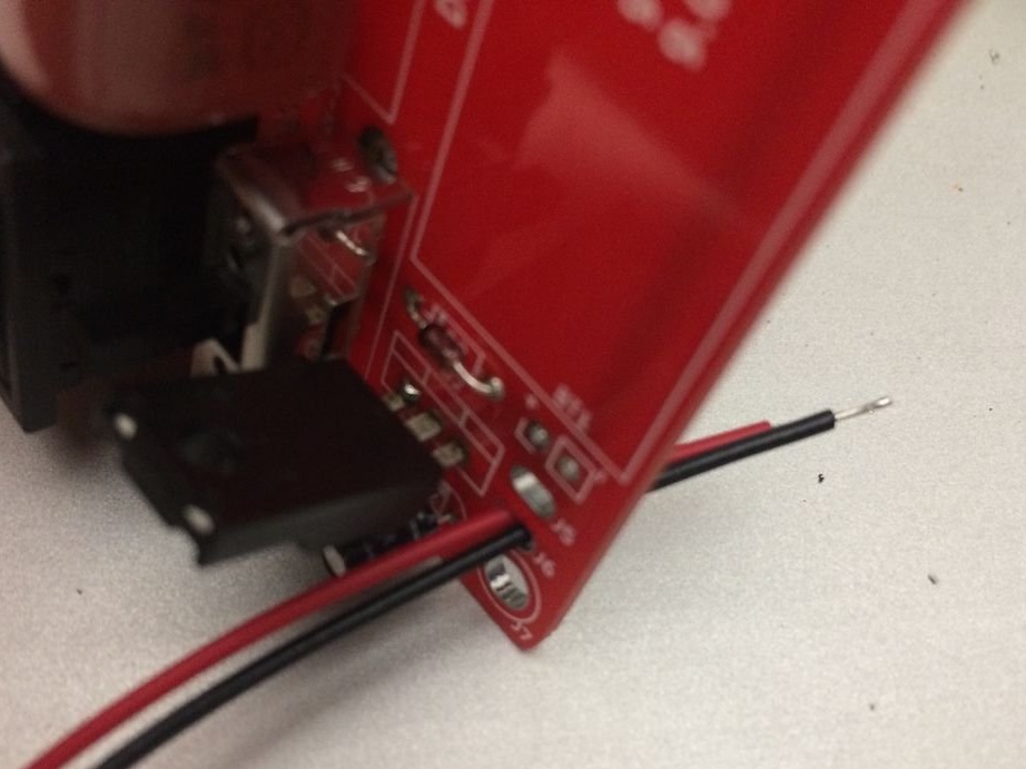
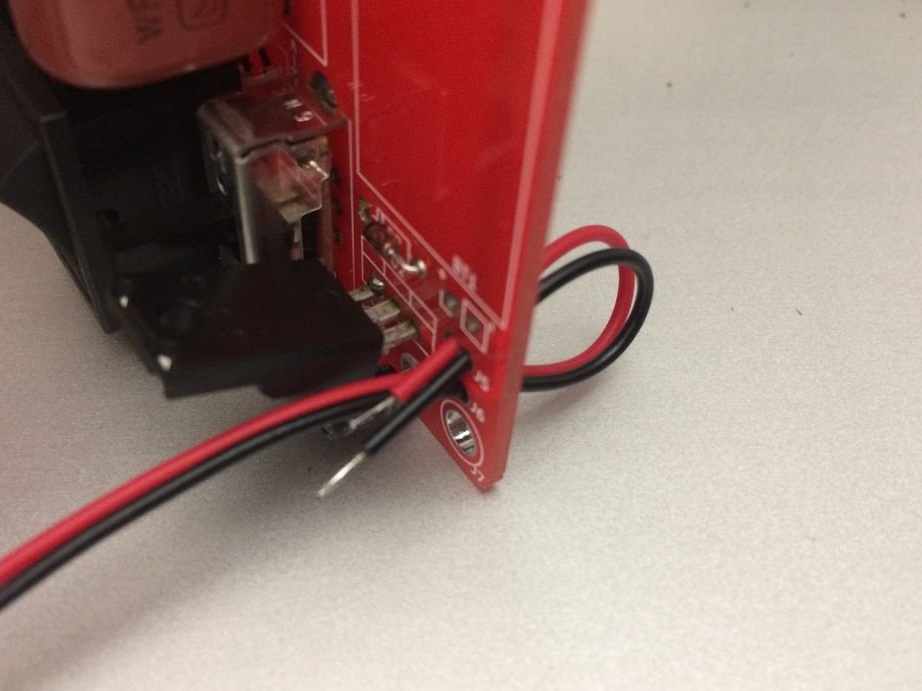
Insert the output wires into the DIMP 2 connector.
Connect the output wires to the battery, making sure the black wire goes to the negative terminal of the battery, and the red wire goes to the positive terminal of the battery.

Turn on the slider and monitor the battery voltage.
Connect 220V to the device.

Turn on the toggle switch and watch for a slow voltage change. It should not change very or very quickly. If the voltage rises sharply and does not drop, the battery is almost certainly not fully recoverable. The voltage on the moderately sulfated battery should jump quickly, then at the rated voltage, drop almost as fast, and then gradually rise as it charges / desulfates. A strongly sulfated battery will immediately rise up, and then hours or even days will decrease to the rated voltage.

Monitor the temperature of the battery and its voltage during charging / desulfation. Heat is bad for your battery.Lithium batteries must be constantly monitored as they may catch fire. Lead acid batteries can give off gas.

Turn off the toggle switch when the voltage reaches approximately 110% of the rated voltage. NiCd and NiMH batteries for power tools typically achieve this from 15 minutes to half an hour. Lithium batteries also charge quickly. For lead-acid batteries, this process takes hours. The voltage should drop, and then find a stable value. If this value is higher than the rated voltage, everything is ready, and you can proceed to the next step. If the voltage drops below the rated voltage, you can try again to go through this cycle, but it is possible that the battery cell or battery pack may not be completely desulfated.
If necessary, you can repeat the cycle.
7.2
6.1
5.6

Add a comment

    • smilesmilesxaxaokdontknowyahoonea
      bossscratchfoolyesyes-yesaggressivesecret
      sorrydancedance2dance3pardonhelpdrinks
      stopfriendsgoodgoodgoodwhistleswoontongue
      smokeclappingcraydeclarederisivedon-t_mentiondownload
      heatirefullaugh1mdameetingmoskingnegative
      not_ipopcornpunishreadscarescaressearch
      tauntthank_youthisto_clueumnikacuteagree
      badbeeeblack_eyeblum3blushboastboredom
      censoredpleasantrysecret2threatenvictoryyusun_bespectacled
      shokrespektlolprevedwelcomekrutoyya_za
      ya_dobryihelperne_huliganne_othodifludbanclose
16 comments
a schema and a link to components
Modern serviced batteries are more compact and not casual have a 3-year limitation period,

Where did they read it? ..
On a serviceable car, and with timely and proper maintenance, and proper initial selection, any modern, cheapest battery runs for at least six or seven years! ... (If the factory marriage did not come out in the first months). More expensive and recognized manufacturers - up to fifteen years! ...
(I'm talking about the "right to use and maintain", and not "put and ride, and if I sat down -" light "... and ride again")))))
instead of lead, its alloy,
. What is the alloy with? And for what purpose ??? (The only thing that comes to mind is purely out of harm !!!))). Evil barmalei producers mixed in plates of unnecessary metal so that their batteries, with the same sizes as competitors, had half the starting currents. ("I will frostbite my nose for evil," this is called.))))
Unless in the "offside" patented technology ("Calcium"). But they are very expensive and rarely found therefore ... Although, with the same sizes and capacities, they can give out twice the starting current. I once bought an old "hundred" such a "Center" with the launch of 1100 A. You could go on the battery!))))). In any frost, a frozen five-pot diesel spun sharply, like from a tugboat!))). I just had time to change the tires on the mass - they burned.)))). He put two at a time. But, if the frost was over twenty (and there was a mineral oil), then while the starter is "razmutloshish" - still burned ...
It's a pity that the battery. I killed him, swept the brushes on the generator - the charger was 13.5, and I rode ... I rode for a long time ... Until he "went deep" ... And then I was on business in another country. I just had to “light it up” and drive on around the city. And this, as you know - death for the battery ... It was possible to remove only after a week ... But it was too late! Sulphates can no longer be defeated ....
Oleg Borodinov
For batteries manufactured in the USSR, this scheme would be relevant, they were more bulky and there was enough space under the plates to the bottom for sedimentation after desulfation, the second moment the quality of lead was much higher and, subject to all operating rules, could work for more than 10 years. Modern serviced batteries are more compact and not casual have a 3-year limitation period, the plates are thinner there, instead of lead its alloy, the plates abut the bottom, if there is a gap then it is insignificant. During desulfatization, sulfate will clog the plates and the process itself will destroy them. You are 30 years late with this device. Using a desulfator will do more harm than good for modern batteries.
Author
The author posted a link to the board. Sells on Ebey along with a stitched chip.
https://www.ebay.com/itm/DIMP-2-Battery-Recharger-and-Desulfator-In-My-Pocket-PCB-and-Pre-programmed-AVR/333424055652
Guest Eugene
Nothing new. Charge-discharge only contributes to a deeper charge of the battery. The chemical desulfation process and recommendations for the practical removal of sulfate have not yet been clearly described. There are attempts to desulfate the battery by replacing the electrolyte with clean water (you know what the replacement threatens). There are recommendations (so far unsubstantiated) of a charge by a pulsed current (for example, a meander). In my opinion it’s no use repeating a regular charger
Guest Alexander
Quote: Guest Alexander
If the battery is in a state of clinical death, more than one beautiful Chinese board will not help her. Do not waste time, and serve your Akum on time, so that you wouldn’t look for it later, what a miraculous thing to revive it!
Guest Alexander
If the battery is in a state of clinical death, more than one beautiful Chinese board will not help her. Do not waste time, and serve your Akum on time, so that you wouldn’t be looking for what a miracle-revival to revive it!
.. there is a more time-consuming option with flushing and charging a battery filled with water ..

This is an unreal option. Because discharge of the electrolyte is not provided for now, but when turning over shit dirt below will be between the plates.
Ehhhh ... Where are you, good old batteries in which you could cut out the mastic, get out the plates, clean, wash and put it back? !!!)))))
And I also had a miracle device in the USSR called "Cedar-M", which really (made sure in practice) crushed sulfates on plates with an electric current ... And it was able to quickly charge batteries.
By the way, there in the instructions it was immediately written "ATTENTION !!! Charging in the" fast "(pulsed) mode is permissible only if there is an urgent need to urgently charge the battery, as it significantly reduces its service life! Use the regular mode for scheduled charging!" ...
And in the modern charger, I read "Superfunction! Fast charge !!! Our device is developed using advanced technology that allows, thanks to the use of a special pulse current, to reduce the battery charge time by tens of times! Do not waste more time! Use our device!"
Guest Nikolay
Quote: pogranec
I found a man’s site, on the scheme of which, with improvements, this device was made. Schemes are true and he does not.
Question: How does the desulfation part work?
Answer: Da Pimp uses a 60 Hz AC signal to charge, it still has a boost after DC conversion. This is the pulse that does desulfation. This is an automatic process that occurs whenever a battery is charged using Da Pimp.
Question: How does Da Pimp know which voltage to output?
Answer: Da Pimp provides any voltage necessary to overcome the internal resistance of the battery. A good 12V sealed lead acid battery can have a voltage of 12.6V. Da Pimp will gradually increase this voltage to 12.9 V, 13.0 V, 13.1 V, etc. You can turn off Da Pimp when the voltage reaches 14 V.
Question: Did you invent this?
Answer: I did not come up with the concept of capacitive charging. My friend contacted me on a 1996 white paper entitled “Capacitive Charger,” written by George Wiseman of Eagle Research. I was skeptical, but intrigued. I wanted to add more to its design, making it safer and more accessible to the masses. So this project was born.


I agree there are such devices. which are with inductive elements or with charge-discharge switching .. there are 2 different principles .. there is a more time-consuming option with washing and charging a battery flooded with water .. BUT THIS device on a red board is useless in terms of desulfation and not only dangerous in terms of electrical injuries
see warning labels on the board!
Author
I found a man’s site, on the scheme of which, with improvements, this device was made. Schemes are true and he does not.
Question: How does the desulfation part work?
Answer: Da Pimp uses a 60 Hz AC signal to charge, it still has a boost after DC conversion. This is the pulse that does desulfation. This is an automatic process that occurs whenever a battery is charged using Da Pimp.
Question: How does Da Pimp know which voltage to output?
Answer: Da Pimp provides any voltage necessary to overcome the internal resistance of the battery. A good 12V sealed lead acid battery can have a voltage of 12.6V. Da Pimp will gradually increase this voltage to 12.9 V, 13.0 V, 13.1 V, etc. You can turn off Da Pimp when the voltage reaches 14 V.
Question: Did you invent this?
Answer: I did not come up with the concept of capacitive charging. My friend contacted me on a 1996 white paper entitled “Capacitive Charger,” written by George Wiseman of Eagle Research. I was skeptical, but intrigued. I wanted to add more to its design, making it safer and more accessible to the masses. So this project was born.
Guest Nikolay
Quote: pogranec
By the way, on ebay there are ready-made kits for assembling such a device. A ready-made collected costs about 1000 rubles on Ali.

You can sell anything .. HERBALIFE from the same breed! I look at the circuit board tracks and details:
a simple charging current source with a capacitor ballast - use is already unsafe. the charge current is switched by engines no more than 1.1A as it is written by silk-screen printing on the board. A digital voltmeter is made on MEGA, which can be powered from the CROWN if there is no power from the network and the camulator is completely discharged. The switch is single-pole - so even with the switch off, it may very well be jerking. The programming connector - which is 10 pins - with such power there is a high probability of burning the computer!
And most importantly - NO DESULFATION will not be there! only recharging with current up to one ampere (doubtful). Voltage limits are also not observed - after reaching a full charge, corrosion of the positive plates will continue!
Guest Nikolay
Quote: Guest Nikolay
Quote: pogranec
Quote: Guest Nikolay
Where is the circuit and firmware? Where to buy a red board?

Article is fresh. We will wait for a response from the source. A link list of the necessary details. Boards and microcircuits are not there. Most likely, it will implement through ebay, as last time.
I will track, and unsubscribe.

Instead of an article, we need a layout of electronic items. Such a description of the "steps" does not have practical meaning .. there is not even a description of the algorithm of the device. Recharge comes from the network via capacitive ballast. Why is the "crown" incomprehensible! where the energy is discharged during the discharge is also not clear.

What is switched by two engines? According to the sealed elements, we can assume that the device is a voltmeter based on MEGA and a small source of charging current on a capacitor ballast is just that! no charge-discharge switching elements are observed!
Guest Nikolay
Quote: pogranec
Quote: Guest Nikolay
Where is the circuit and firmware? Where to buy a red board?

Article is fresh. We will wait for a response from the source. A link list of the necessary details. Boards and microcircuits are not there. Most likely, it will implement through ebay, as last time.
I will track, and unsubscribe.

Instead of an article, we need a layout of electronic items. Such a description of the "steps" does not have practical meaning .. there is not even a description of the algorithm of the device. Recharge comes from the network via capacitive ballast. Why is the "crown" incomprehensible! where the energy is discharged during the discharge is also not clear ..
Author
By the way, on ebay there are ready-made kits for assembling such a device. A ready-made collected costs about 1000 rubles on Ali.
Author
Quote: Guest Nikolay
Where is the circuit and firmware? Where to buy a red board?

Article is fresh. We will wait for a response from the source. A link list of the necessary details. Boards and microcircuits are not there. Most likely, it will implement through ebay, as last time.
I will track, and unsubscribe.
Guest Nikolay
Where is the circuit and firmware? Where to buy a red board?
Without this, article translation does not make sense.
The links also have none of this ..

We advise you to read:

Hand it for the smartphone ...