

Glad to welcome you again. I really like displays for Arduino type OLED. Specifically small with a diagonal of 0.96 inches with a resolution of 128 by 64 pixels. If you look at my page on this site, you can find many different projects with this display. Devices such as a voltmeter or ammeter with such a display, of course, are compact, but are rarely used, and it is more convenient to use a ready-made multimeter sold in any radio store. And I want my homemade stood on the table and delighted the eye, with every look at her, every day. Therefore, a watch is the best solution for this. I had many options for watches with this display, on Arduino, on Attiny85, on batteries, powered by USB, with backlight, with a thermometer, etc., etc. But all of them had some drawbacks: unstable food, an ugly case, not enough memory to implement the date display function (Attiny85). But as a result of a lot of trial and error, I found the optimal solution for my requests. This time we will use:
- Typewriter Modarri
- Arduino Pro Mini 5v 16 Mhz
- DS28B20 (Digital Temperature Sensor)
- WS2812 (Address LED Strip)
- USB-TTL (To fill the sketch)
- OLED 0.96 128x64
- Buttons
- Circuit board
- Resistor 4.7 kOhm
- Ceramic capacitor 104, 2 pcs
- Sheet plastic 1-2 mm thick
- connecting wires
- USB wire
- Glue gun
- Oil seal and everything you need for soldering
Step 1 Choice of housing.
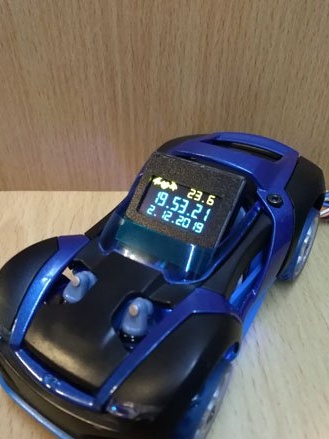
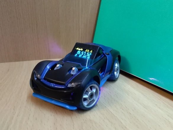
After long and painful attempts to make a watch case so that I liked it, I decided to look for the basis for the case on my (and not only on my own) shelves. I saw cars that I like. These are small, well-made, with rubber wheels and shock absorbers Modarri toy cars
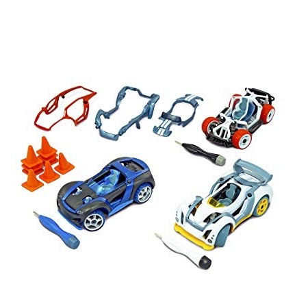
This company has a wide range of products. Cars are for every taste and color. And most importantly for us, they have a place provided for finger control. And it is great for our small screen. I found three models:
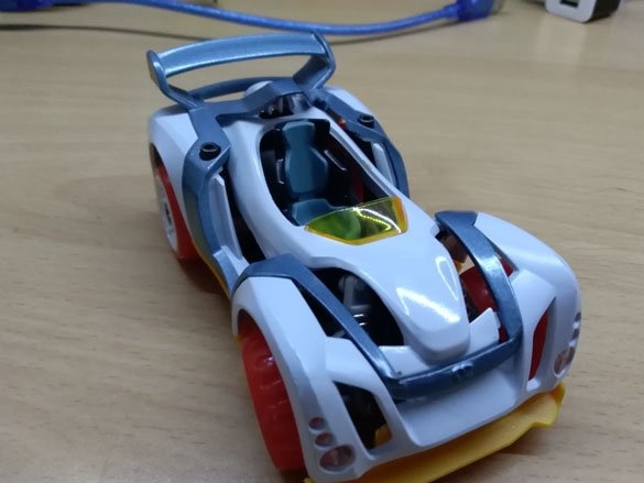
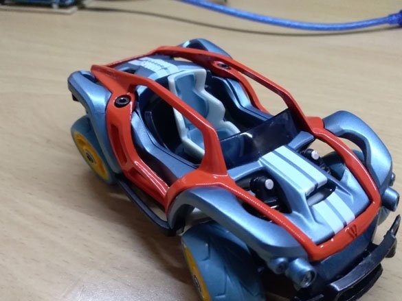
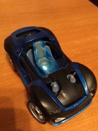
You can make such a watch from any one, but I like the black ones most of all. Also, many machine parts are interchangeable, you can assemble as you like.In my opinion, this is an excellent case, made neatly, looks beautiful and there is enough space for electronics.
Step 2 Preparing the screen.
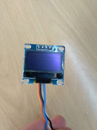
Our screen is small, but cute is a graphic display. Of the features, it is worth emphasizing that each pixel is an independent LED. OLED stands for organic light-emitting diode. 4 wires are used for connection. VCC (positive power wire, can be powered from 5 or 3.3 volts), GND (negative power wire), SCL and SDA (connected to Arduino). The connection to the Arduino is via an I2C serial asymmetric communication bus. The display itself looks like this:
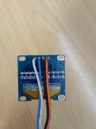
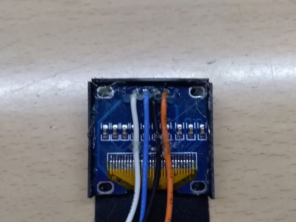
Solder the wires to all 4 contacts, it is better to use multi-colored wires and write down which leads to which contact:
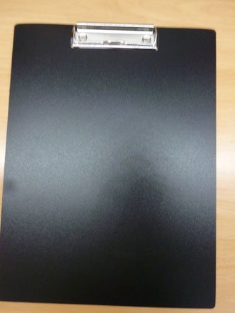
So that the external screen does not spoil the overall look, we will make a small case for it. A small sheet of thin plastic is suitable for the case. For the sake of hours, I sacrificed a stationery tablet:
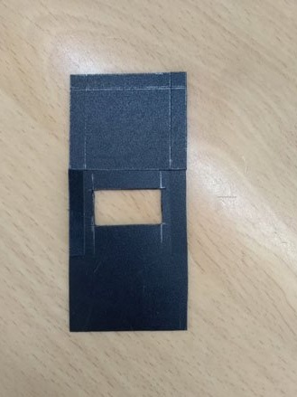
It was perfect for making the case. According to the following scheme, we cut out a small case from plastic:
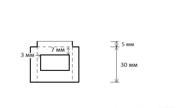
The inner rectangle must be carefully cut, and bent along the dashed lines:
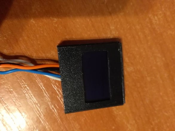
We place our display inside, we fix the screen and the side walls with hot-melt adhesive, it is also better to fill in the wires with glue so as not to tear them out, if suddenly, accidentally hook on:
From the outside it should be like this:
Step 3 Prepare the temperature sensor.
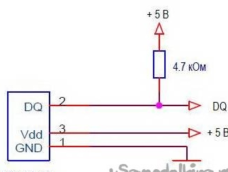
Well, what a watch without a temperature sensor! The best choice is a digital sensor. The most affordable is the DS28B20. About its advantages, you can talk endlessly, so in short. It does not use an Arduino processor to calculate the temperature, it connects just one wire to the Arduino (it works using the OneWire protocol). DS28B20 can be connected in many ways. Use an external power supply, feeding it from 5 volts through the VDD pin, spurious power by connecting the VDD and GND contacts, or you can find an improved stray power circuit. All options have their pros and cons. We will focus on external power, we will connect VDD to +5, GND to GND, DQ to the Arduino pin, we also need to use a 3.3 kOhm resistor to tighten the DQ to power. The scheme is as follows:
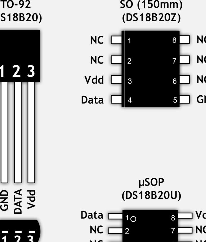
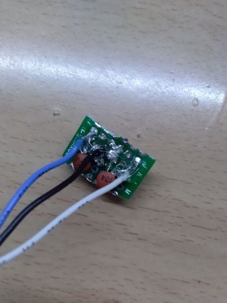
The resistor is most conveniently placed next to the sensor, soldered between the legs. I release DS28B20 in different cases, it is best to take in the TO-92 case. The pinout of the sensor is as follows:
The middle contact is the DQ - data bus, solder the wire to it and one of the resistor contacts (4.7 kOhm):
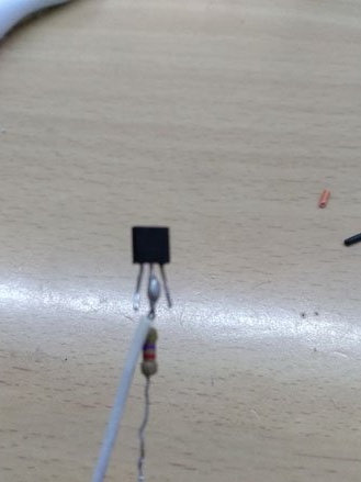
We isolate the middle contact from the lateral ones using electrical tape. We bend the second leg of the resistor, and together with the wire we solder to the Vdd pin. Assign the third GND pin, record the colors of the wires and isolate all the remaining contacts.
Step 4 Preparing the control buttons.
Setting the time and date will be possible in two ways. Via port monitor or buttons. In the sketch of the watch, the use of three buttons is provided (Set, Plus, Minus). But you can get by with two by turning off the minus button. Solder the buttons on the circuit board:
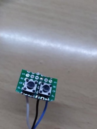
Do not forget to record the colors of the wires to know which leads to. Buttons have one of the wires in common, it will connect to GND. In parallel with the buttons, we solder the ceramic capacitors with the marking 104 (eliminate the effect of rattling of the contacts).
Soldered wires are better to fill with hot glue.
Step 5 Prepare WS2812.
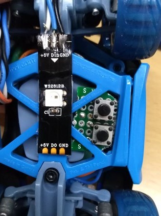
The address tape WS2812, or rather just one LED WS2812, we will use to highlight the machine. I cut off one LED from the tape, but you can purchase them separately. We glue WS2812 from the bottom of the machine and solder the following wires to it: +5 (positive power wire), GND (negative power wire), Din. Please note the address tape has a signal direction. Therefore, the signal wire must be soldered to the terminal Din (signal input), Do not leave unsoldered:
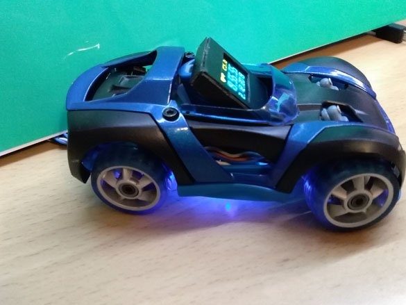
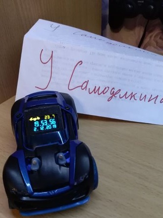
LED is needed for decoration. It is optional, the watch will work without it. Running a little ahead, a photo of the backlight:
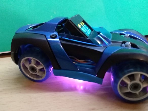
There are 5 highlight colors in the sketch, but you can add your own colors by editing the sketch.
Step 5 Placing all the electronics in a typewriter.
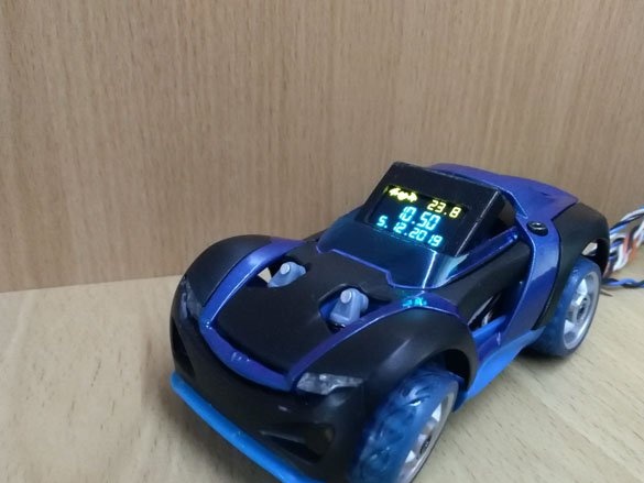
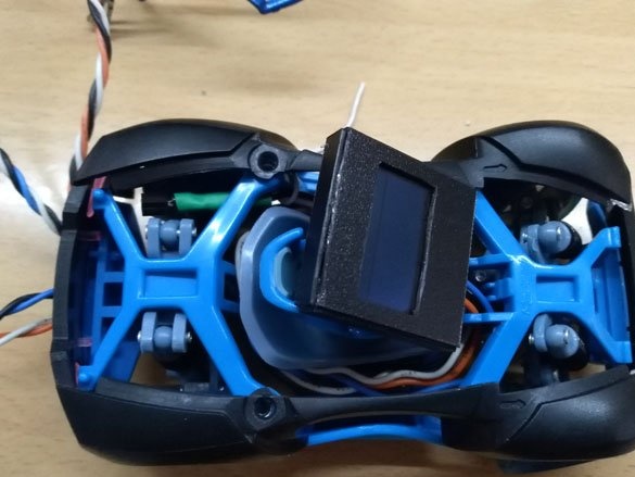
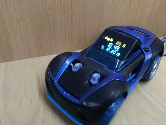
So, finally, move on to the typewriter. We disassemble it. We place the previously prepared display in place for the finger:
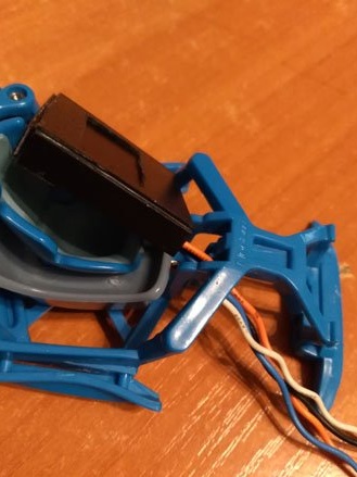
We conduct wires from the display on the right side of the chair. The temperature sensor DS28B12 is placed above the left rear wheel. The wires from the sensor should be fixed, and the sensor itself should hang on the wires without touching the parts of the case:
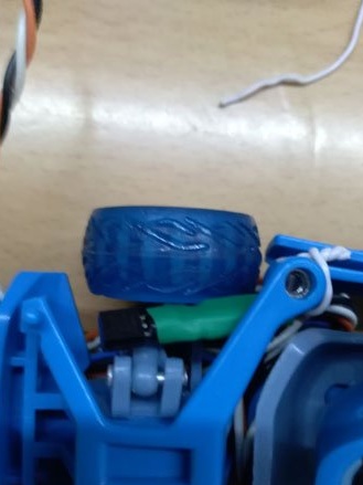
Arduino will be placed on the left side of the chair. We get all the wires there. We place the board, and solder the wires in place, it is easier to calculate the length of the wires. The machine will be powered by USB. In one bundle it will be necessary to twist and solder many wires for power. I recommend twisting and soldering them at a small distance from the Arduino, place them in the rear bumper, and bring only two power wires to the Arduino. The connection is as follows:
USB +5 - Arduino +5 - Oled Vcc - DS28B20 Vdd - WS2812 +5 (twist and solder together)
USB GND - Arduino GND - Oled GND - DS28B20 GND - WS2812 GND - Common from buttons (twist and solder together)
Oled SDA - D8 Arduino
Oled SCI - D9 Arduino
1 Set Button - D2 Arduino
2 Plus Button - D3 Arduino
Minus Button 3 - D4 Arduino (optional)
WS2812 Din - D5 Arduino
DS28B20 DQ - D10 Arduino
Pin numbers can be changed in the sketch. After soldering all the wires, you can start assembling the case:
Step 6 Edit and fill the sketch.
As usual, we need the Arduino IDE programming environment. We go on official site and download it.
We make it more convenient for you. You can download the installer, or you can just archive it, there is no difference.
Now we need the libraries:
OLED_I2C - comes with the Arduino IDE
OneWire - download link below
Adafruit_NeoPixel - Download link below
You can install these libraries by going to the "Library Management" section of the Arduino IDE itself. Find them by name and install. If you have problems with the Internet, download the archives below and unzip it into the “libraries” folder located in the place where you installed the Arduino IDE.
I have two sketches for this watch. First with seconds display:
And the second option without seconds:
Choose to your taste from the files below.
Download project files