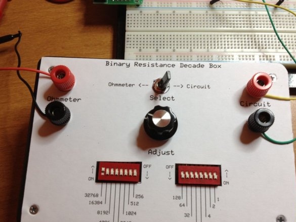
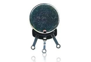
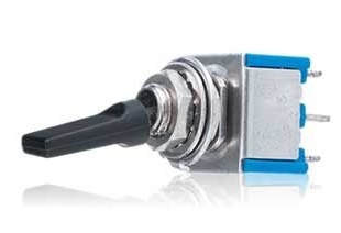
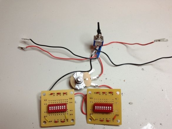
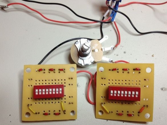
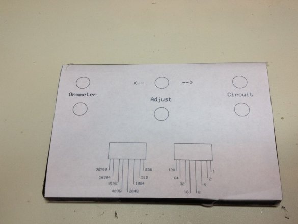
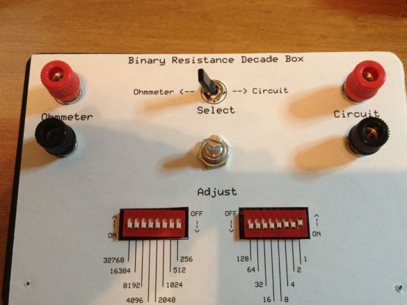
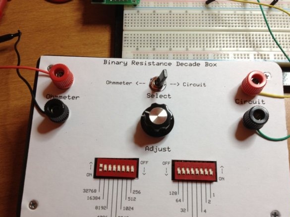
The author of Instructables under the nickname mikesoniat designed and manufactured do it yourself unusual resistance store. From other similar designs, this homemade differs in that the resistance is set not in decimal, but in binary form, according to the principle of the well-known Covox device. After setting the number on all DIP switches, you can switch the resistance store to an external ohmmeter with a toggle switch, additionally set the value more precisely to a small extent with an analog variable resistor, and then switch it back to the adjusted circuit with the same toggle switch. If the circuit is afraid of increasing resistance to infinity, it is necessary to carry out these manipulations by first removing power from it.
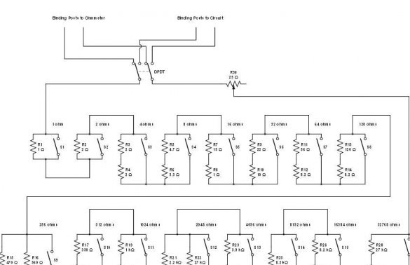
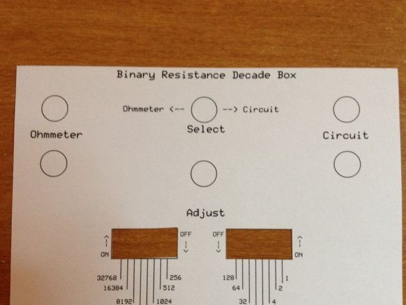
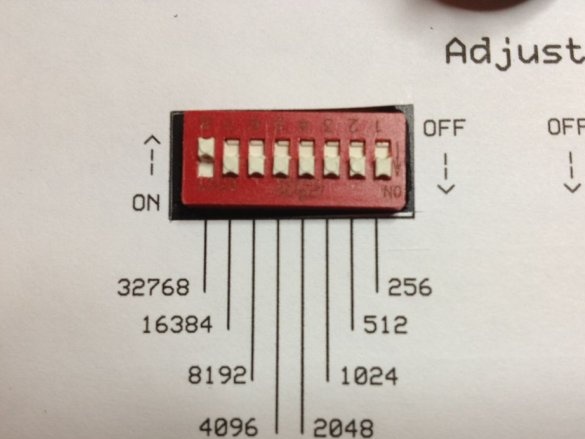
As can be seen from the KDPV, the device uses a 16-bit DAC with discharge weights from 1 to 32768, so the minimum number is 0 and the maximum is 65535. Zero the short circuit of the probes to each other (it is impossible to obtain superconductivity here for obvious reasons) , and the maximum is a resistance of 65535 Ohms.
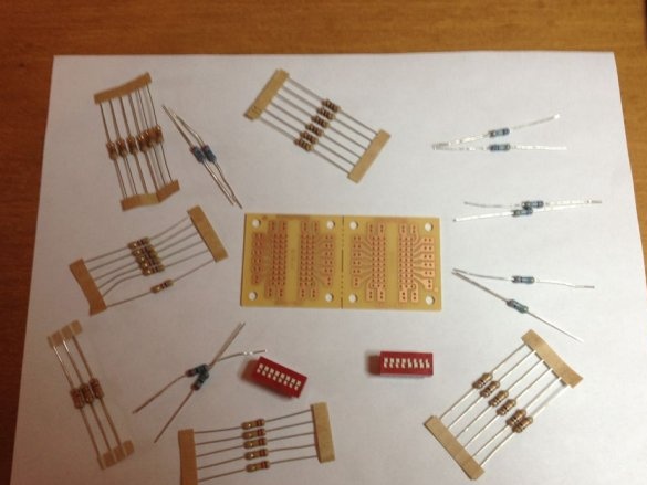
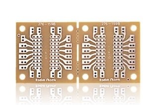
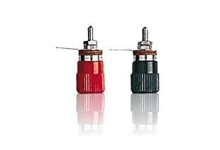
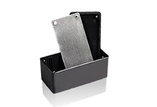
Next, the wizard shows the components necessary for repeating the resistance store. Notes:
1. You can solder DIP switches without risers, directly.
2. The junction box can become the most budget housing, a little less budget - plywood.
3. Designations on the front panel can be applied in another way.
Having decided on the components, the wizard makes a diagram:
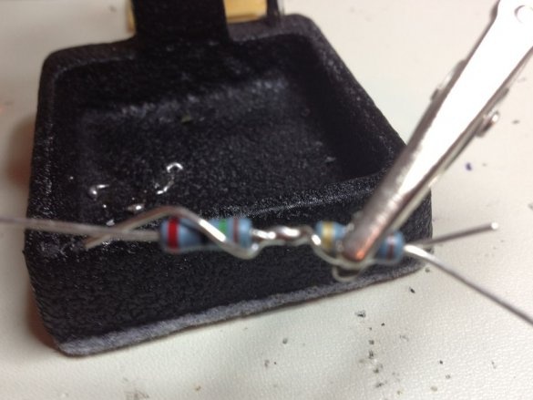
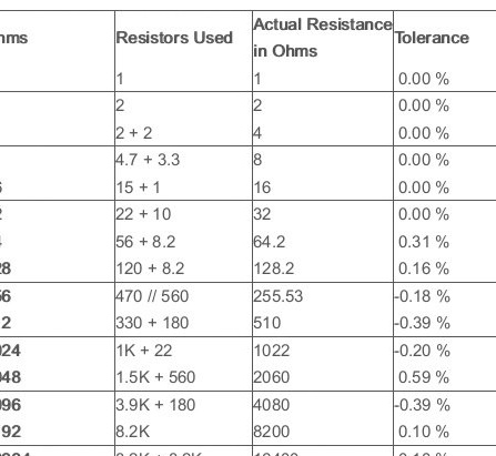
Yes, this is really a DAC on resistors, and some of them are composite, since there are no such ratings in the standard series. The accuracy requirements for resistors are different, depending on which category they are installed in. For convenience, this information is summarized by the master in a table, where the series connection is indicated by a plus, and parallel fractions by two fractions:
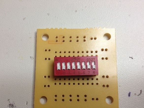
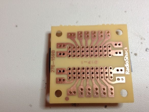
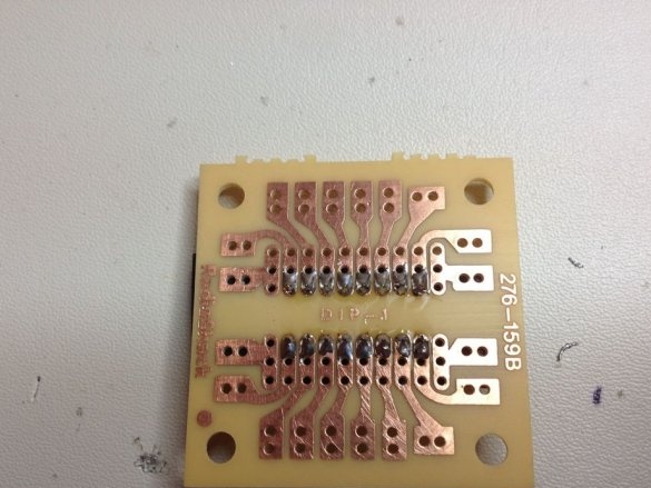
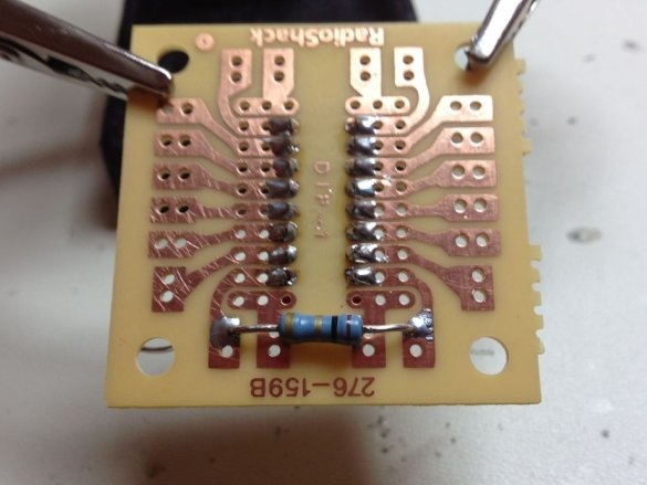
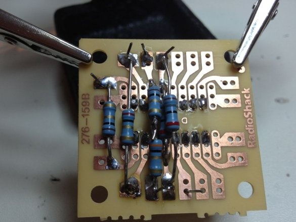
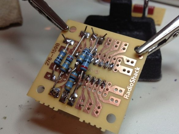
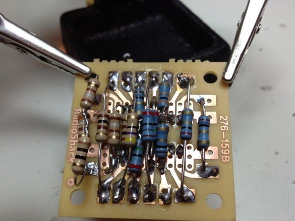
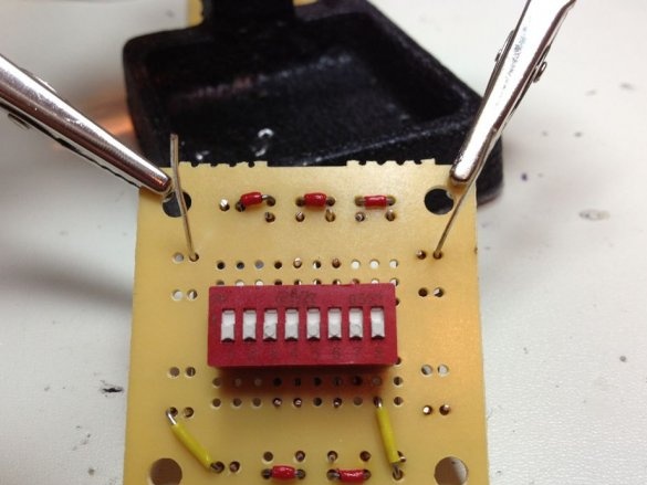
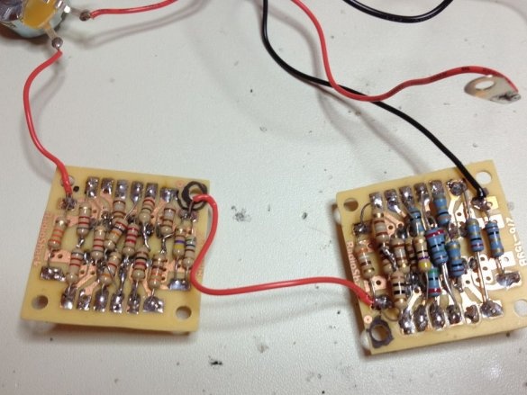
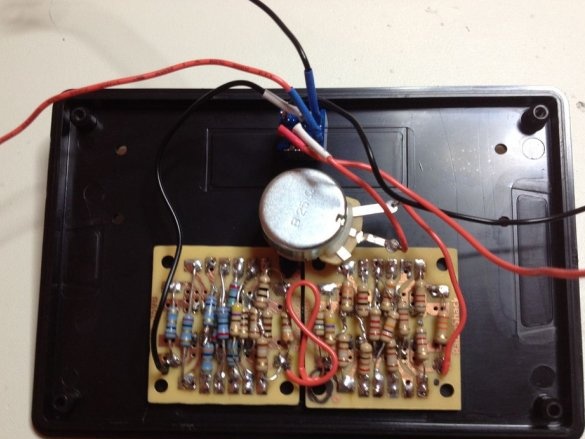
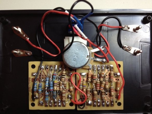
The wizard starts assembling the circuit. As you can see, the adapter boards for the DIP switches turned out to be very convenient for assembling the DAC directly on the reverse side:
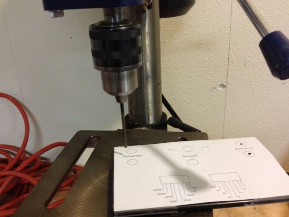
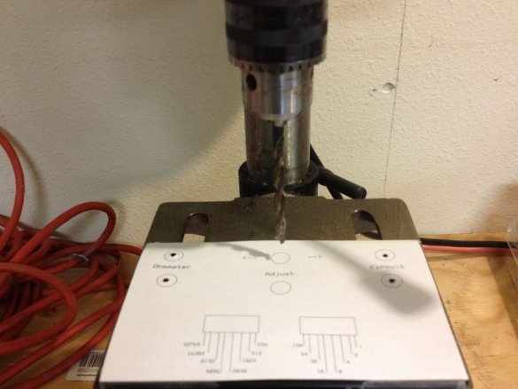
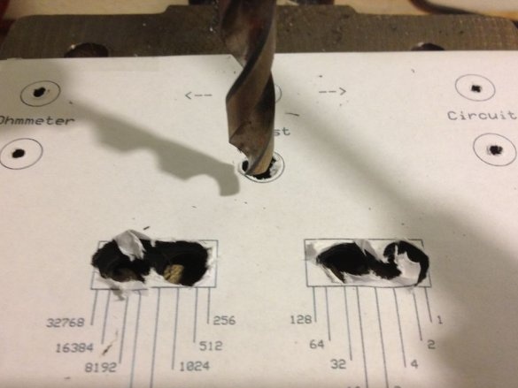
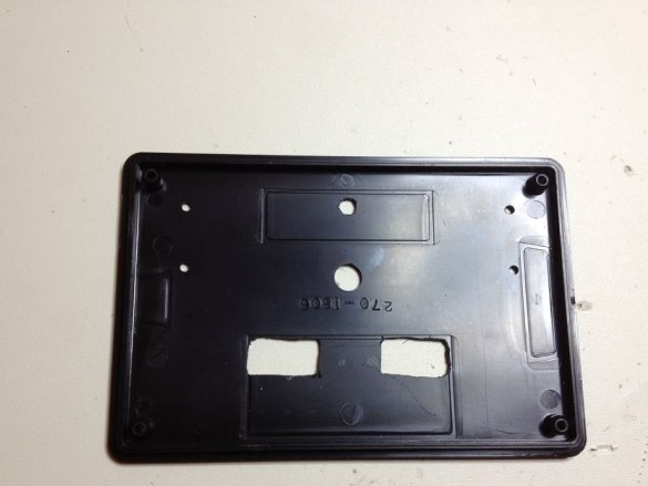
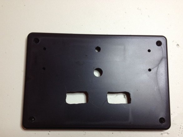
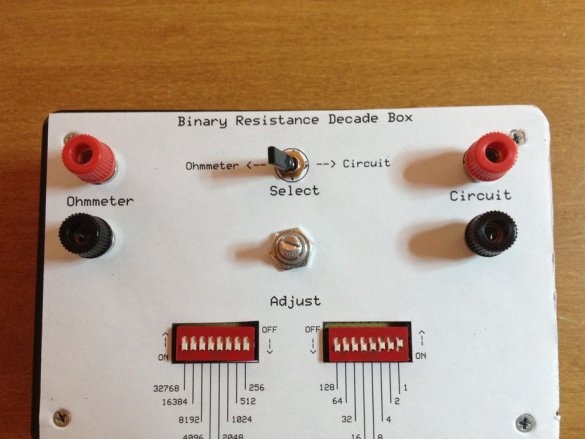
Prepares the case: imposes an analog sticker printed on plain paper, drills holes:
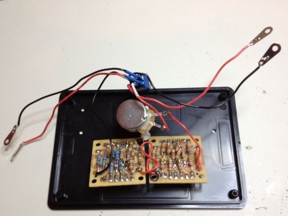
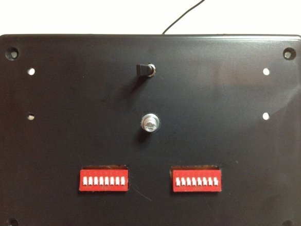
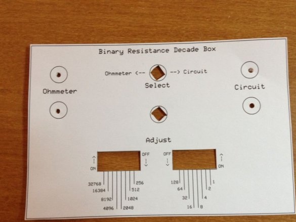
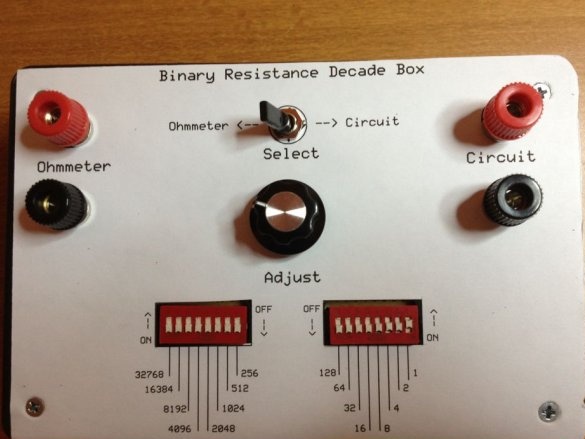
It transfers the assembled DAC to the case, this time printing a sticker on special paper:
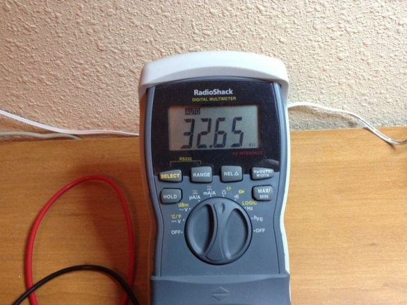
And finally, everything is tested by connecting a multimeter operating in ohmmeter mode. It sets one or another number on the DIP switches in binary code and checks whether the resistance is obtained that is close enough to the calculated one. Then he slightly corrects it with a variable resistor and makes sure that the result corresponding to the calculated one is obtained.
The dissipated power maintained by the device in each particular case is determined by that of the resistors at which the maximum power is allocated in the current configuration - it should not exceed the nominal one. If you need to make the resistance store more powerful, you should use more powerful resistors, and also replace the DIP switches with toggle switches.

