
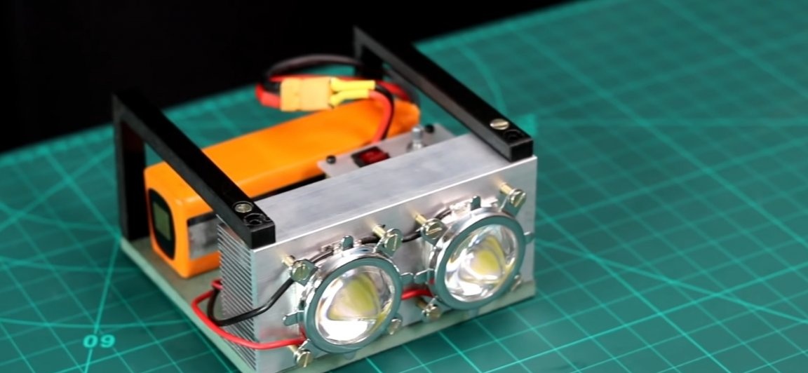
Hello friends! Today we will gather together a very interesting homemade, namely, we will assemble a flashlight at 200WT. This lantern is already difficult to call a lantern, as it shines like a real spotlight. The flashlight itself will be very compact and mobile. It will be powered by a Li-po battery, which is able to work at high current for quite a long time, compared to NI-CD batteries (which most Chinese put in their cheap flashlights). This lamp will be very useful to all those who lead an active lifestyle and often go on hikes, because there are often situations when something needs to be highlighted in the dark. This flashlight is very compact (for its power) and the place in the backpack will not take much. And in turn he will be able to highlight, a whole clearing, forest paths, etc. Well, well, I think you should not delay with a long introduction, they drove.
Links to the main components of the homemade product can be found at the end of the article.
For a home-made 200-watt LED flashlight, we need:
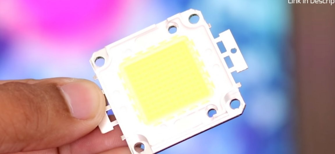
- Two 100W LED matrices
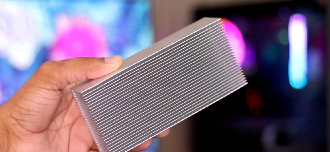
- Aluminum radiator dimensions 150x69x36mm
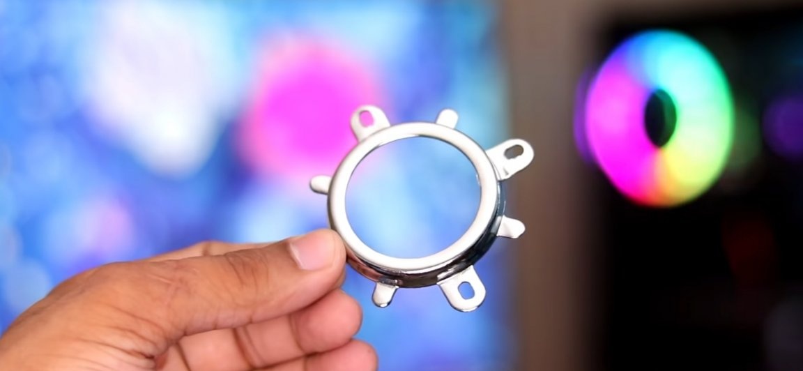
- Lenses and mounts for them in the amount of 2 pcs.
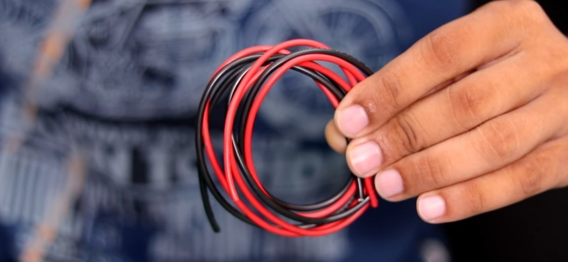
- Power wires
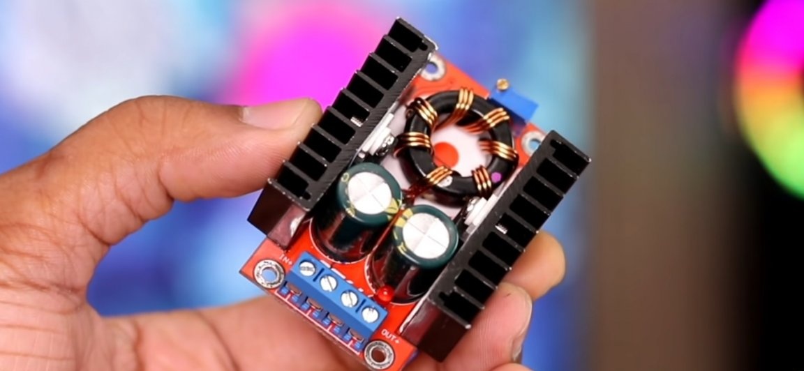
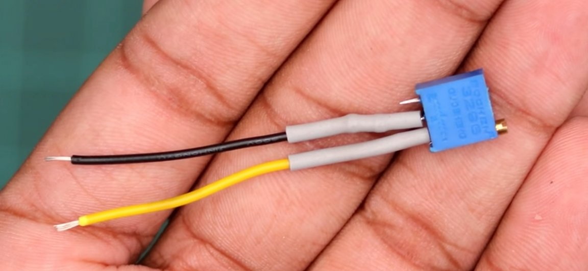
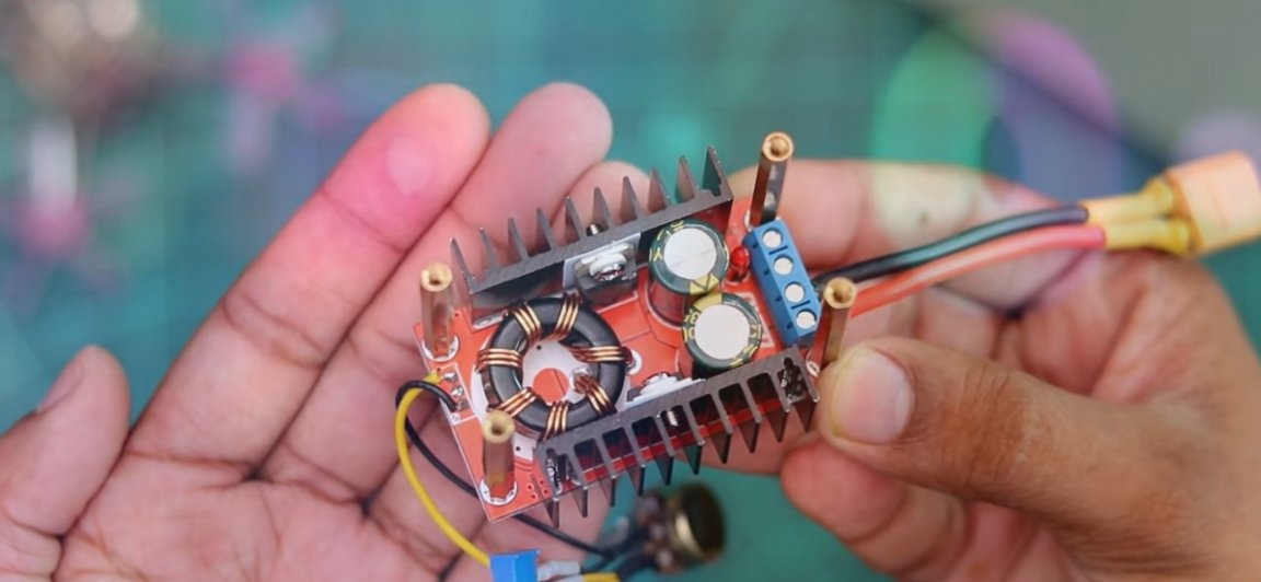
- DC voltage regulator (DC-DC)
- 10K resistors 2 pcs.
- Potentiometer B10K
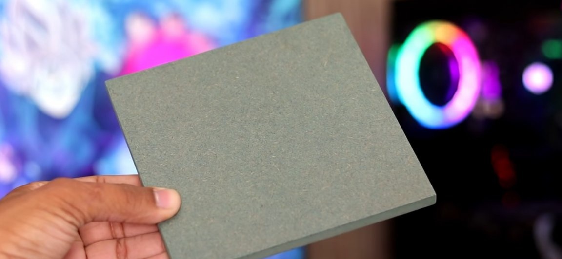
- A piece of MDF panel ~ 150 * 1500mm
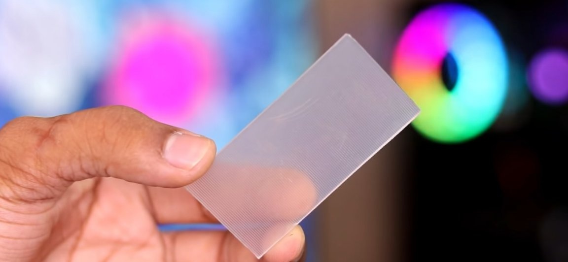
- A small plastic plate.
- Switch (more powerful)
- Connector XT-60
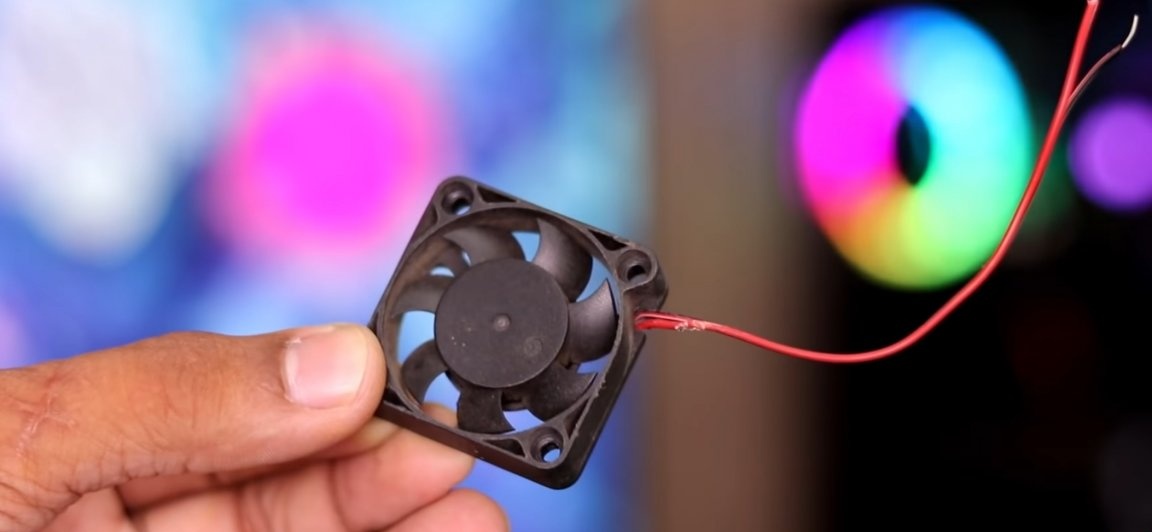
- Small cooling fan
From the tools you will also need:
- Soldering iron with soldering accessories
- Super glue
- Drill with drills
- screwdrivers
- marker
- Multimeter (enough voltmeter)
- screws
- Tap (piece for threading inside cylindrical parts)
- Thermal grease
- Shrink
- Nippers
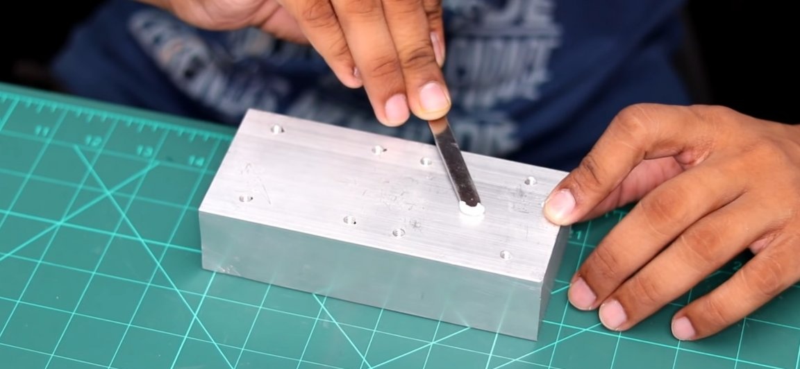
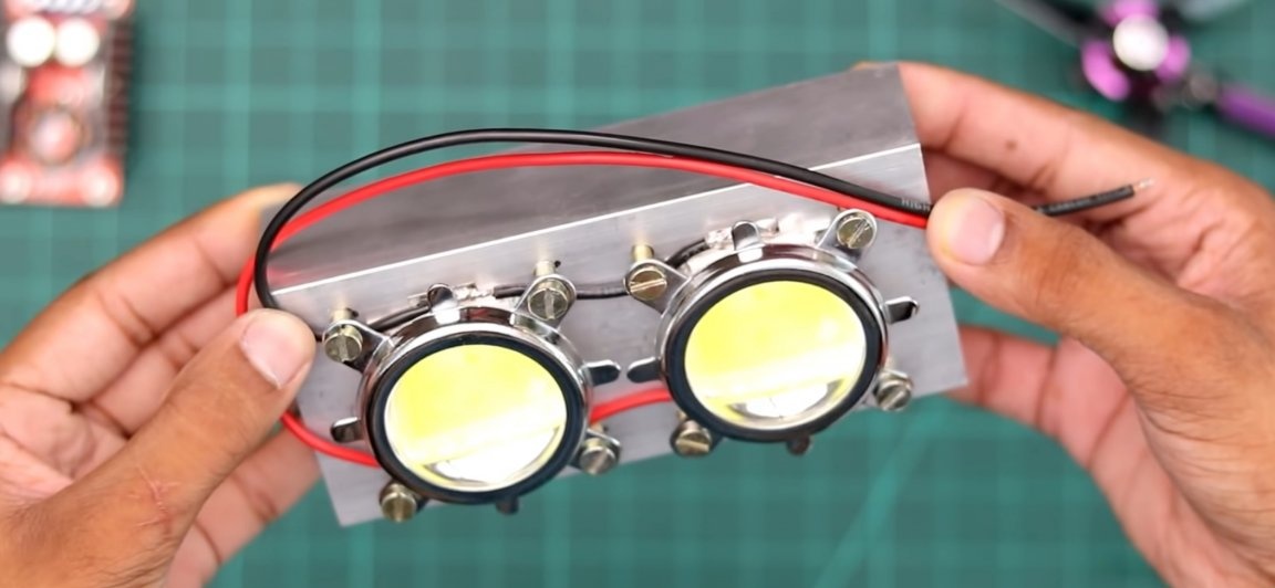
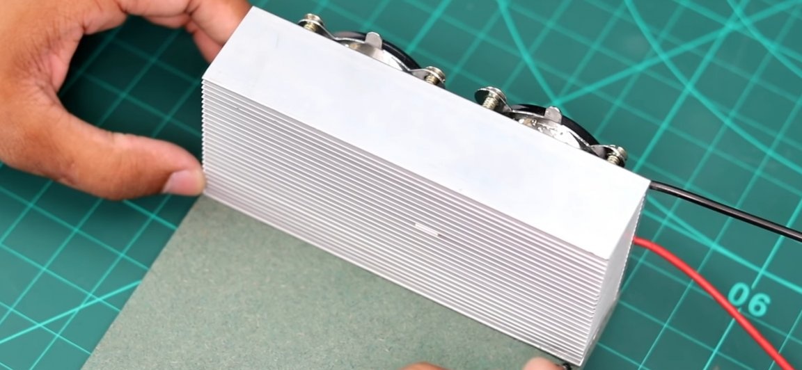
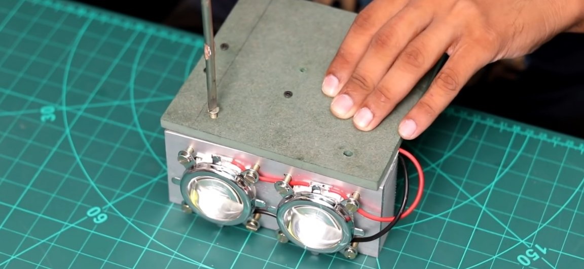
Well, let's proceed to the assembly of the lamp. To begin with, let's collect the light part itself. For it, we need to take a cooling radiator that is suitable in size, on which we will fix the LED matrix. The author of the homemade product took a radiator with a size of 150x69x36mm as it fits perfectly in size, and most importantly, you can get it from our Chinese friends without any problems.
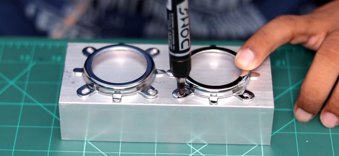
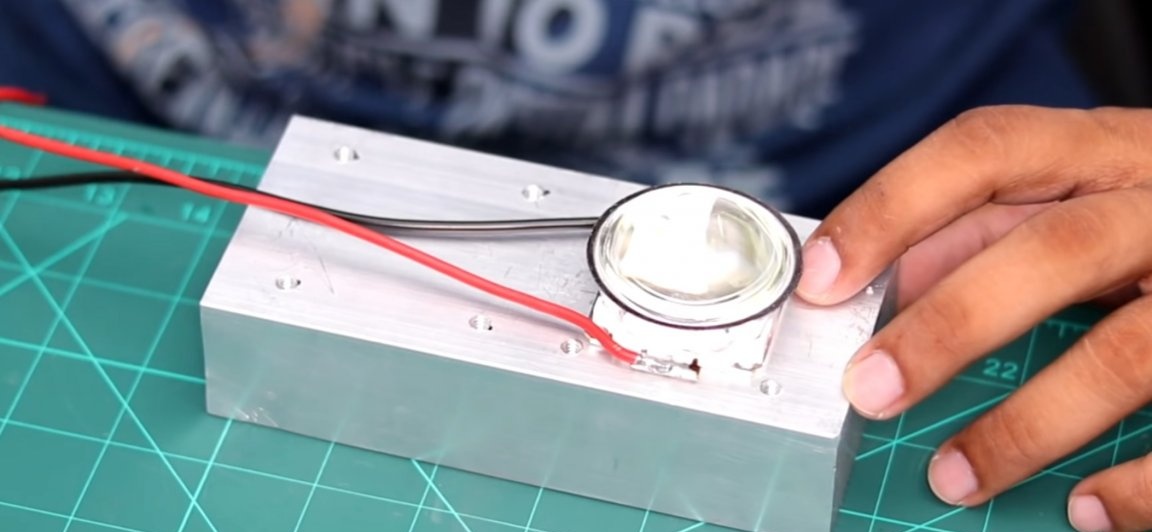
Having picked up the basis for the light part, we fix LED matrices on it. To do this, take the lens mounts (they come complete with the lenses themselves) and attach them to the flat part of the radiator, so that they are located in the center (see photo). Then, using a marker, we will leave marks on the radiator, under the mounting holes.
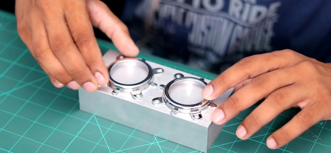
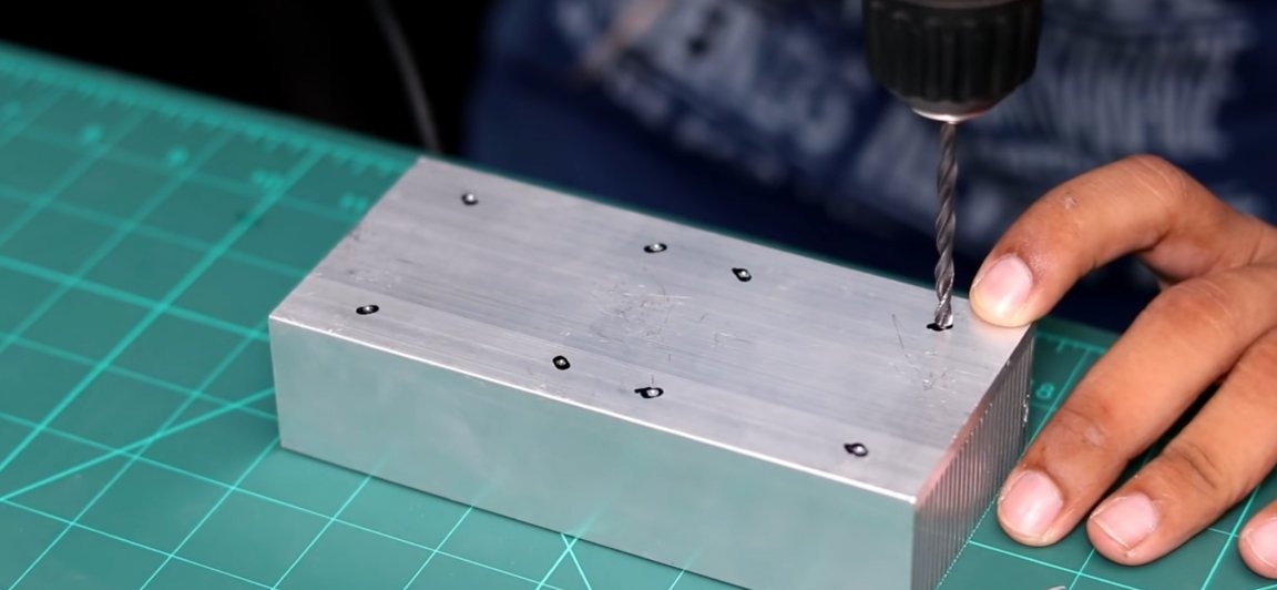
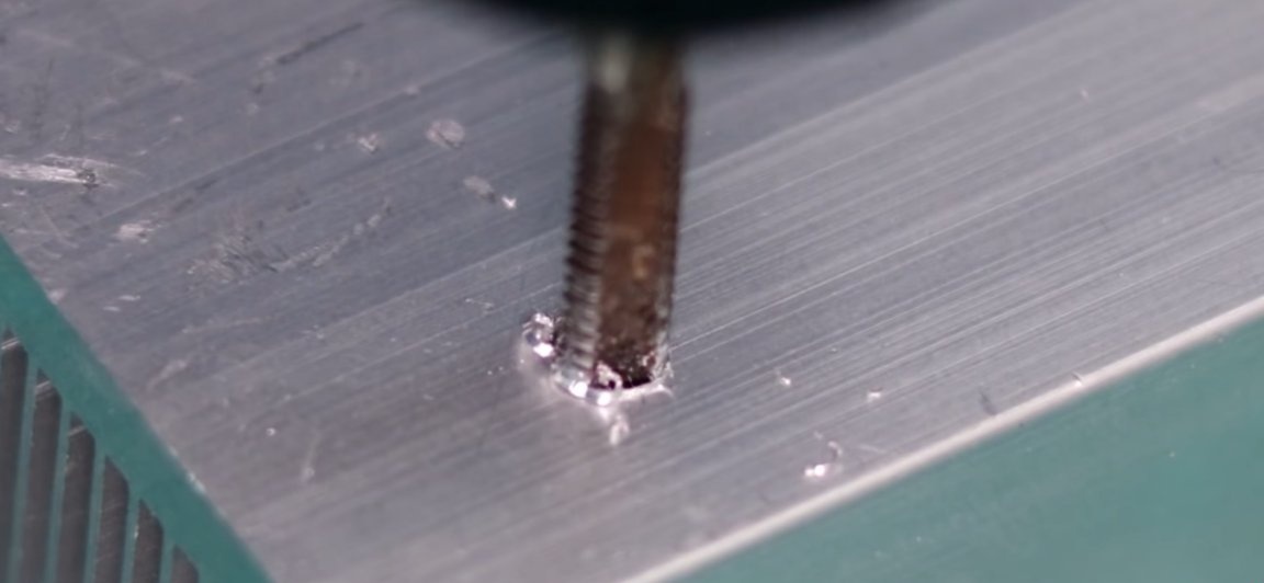
Then, using an ordinary drill and drill of a suitable diameter, drill holes. And then with a tap we will cut the thread so that our screws can be screwed in without problems.
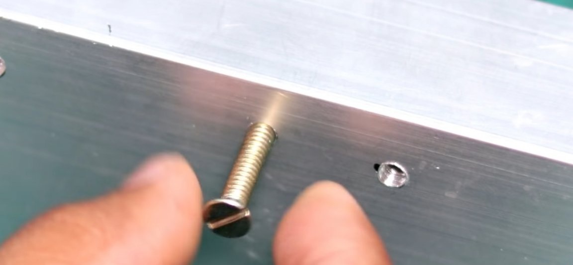
The next step is to take the LED matrix and solder two power wires ~ 10 cm long to its contacts. Next, take and fix it on the radiator. To do this, we apply a small amount of thermal paste on the radiator for better heat removal of heat from the matrix to the radiator, on the radiator itself. Then just “glue” the LED matrix with a radiator. Then we attach a lens to the matrix with a mount pre-installed on it and fix them by screwing the screws into the mounting holes previously done.
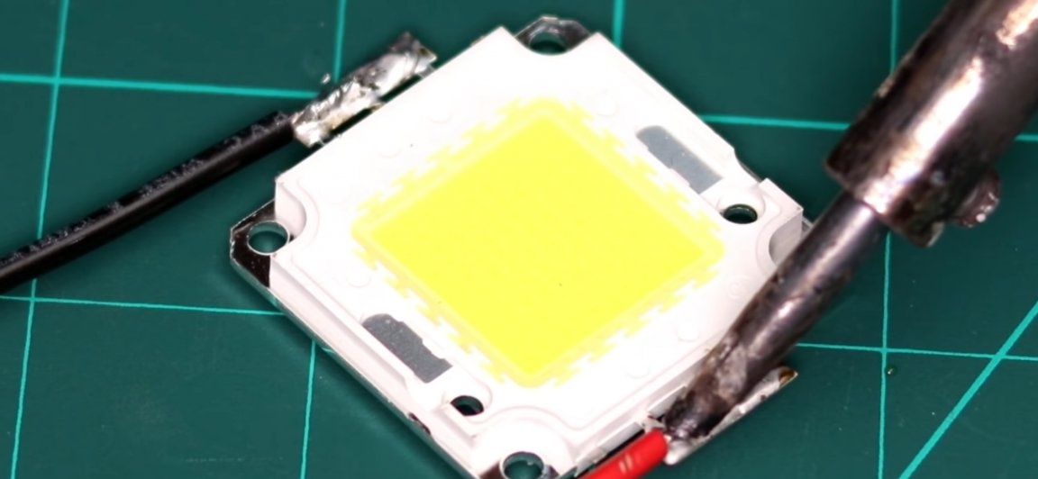
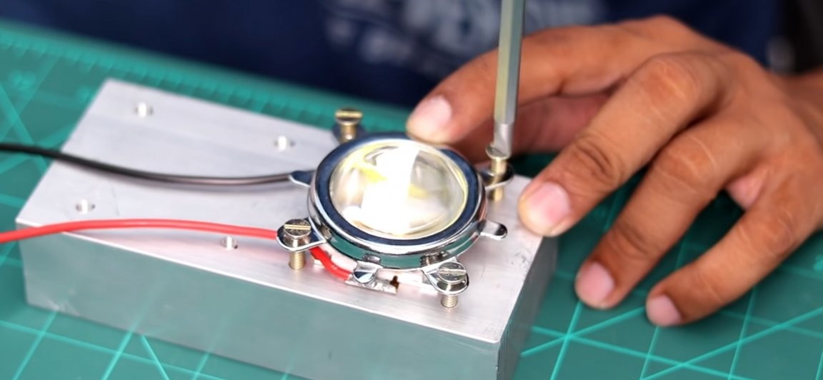
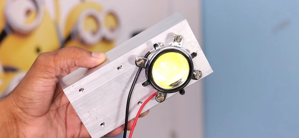
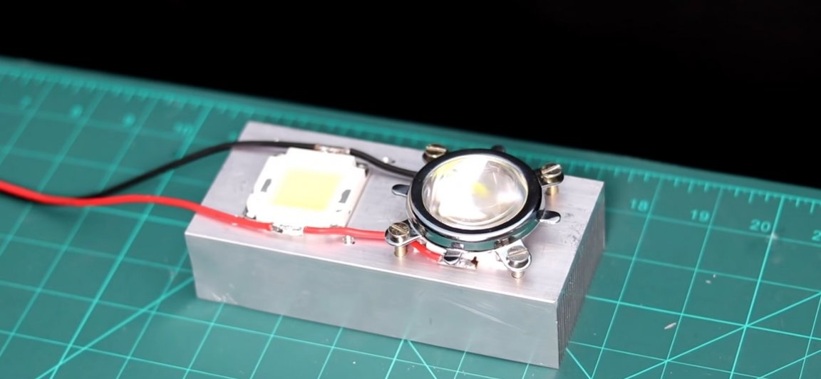
We repeat the same actions with the second LED matrix. But before attaching the second lens, the LED matrix should be connected in parallel to the first matrix. To do this, expose the insulation of the wire in place of its soldering to the contacts of the matrix (see photo).
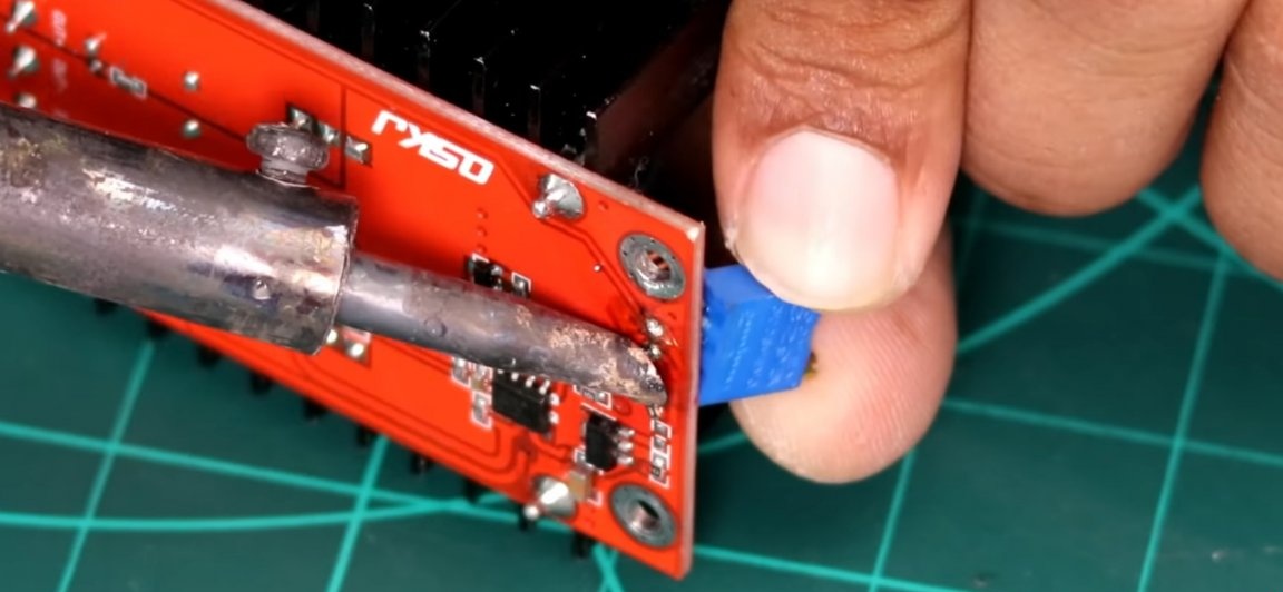
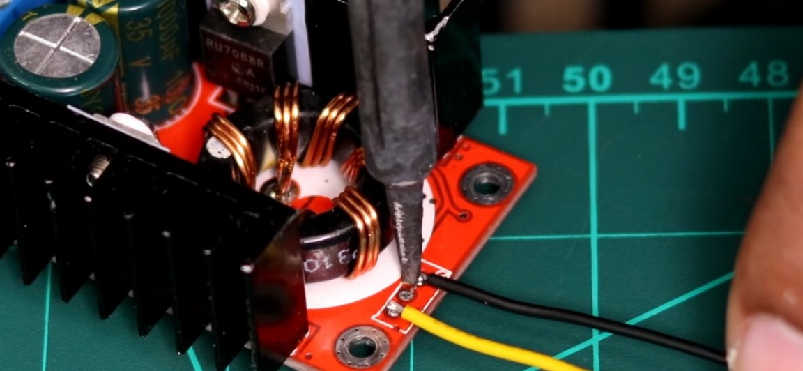
Then we’ll deal with the DC voltage regulator (DC-DC). To begin with, the standard potentiometer should be soldered from the regulator. And do the following with this potentiometer. We solder a 10k resistor to the middle contact of the potentiometer, for this we bite off the extra length of the resistor legs and solder a small piece of wire to its other contact. Solder another small piece of wire to the extreme contact of the potentiometer (on the side of the adjusting screw).
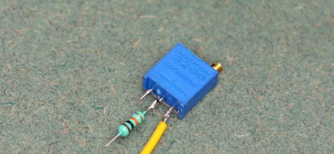
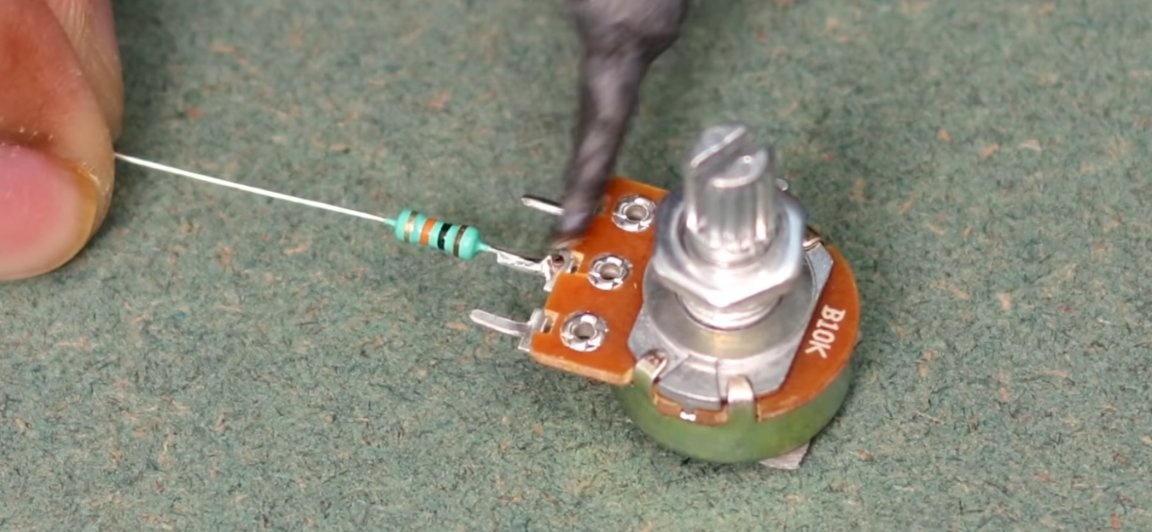
Then we take a potentiometer B10K to the central contact of which, we also solder a 10k resistor. And just the same, solder a piece of wire only to its leftmost contact (see photo). After the operations performed on the potentiometers, they should be “crossed”, namely, just for everything we sing the wires in exactly the same way as shown in the photo below. It is worth noting that you should use heat shrink to insulate bare contacts, well, just for a more aesthetic appearance of the structure.
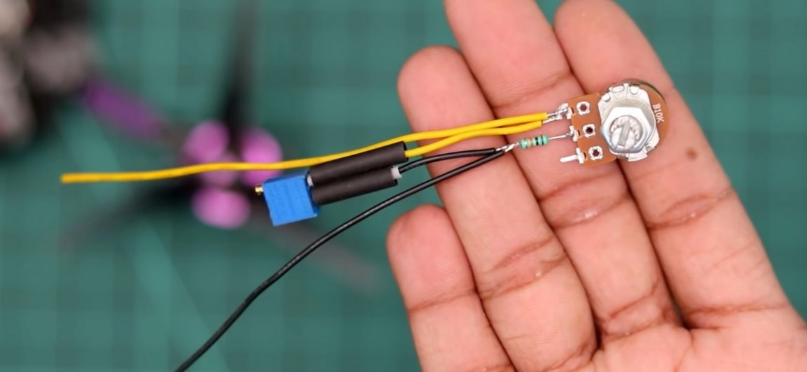
We solder our bundle of potentiometers to the extreme contact, from where one of the potentiometers was previously soldered. Solder should be exactly the same as shown in the photo below.
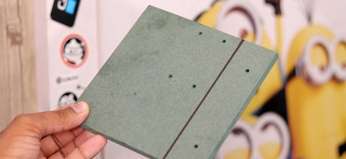
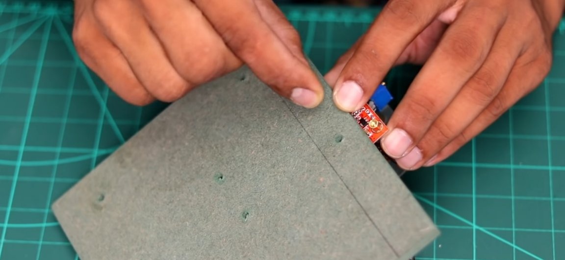
Then we need a base on which all the components of our flashlight will be located. For this, a small segment of an MDF panel (~ 150 * 1500mm) is perfect, since MDF is a dielectric and is very easy to process.
At the edge of the MDF panel, we place the light part (radiator with LED arrays), and with the help of a marker we mark the area in which the radiator will be installed and in the center we leave two marks for the mounting holes. Then next to the radiator we place a voltage regulator, for which we also mark the labels for the mounting holes. Then, with the help of a drill, we make the holes themselves.
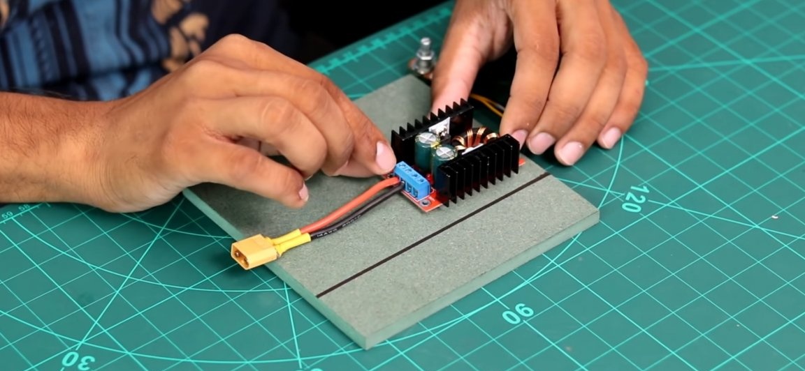
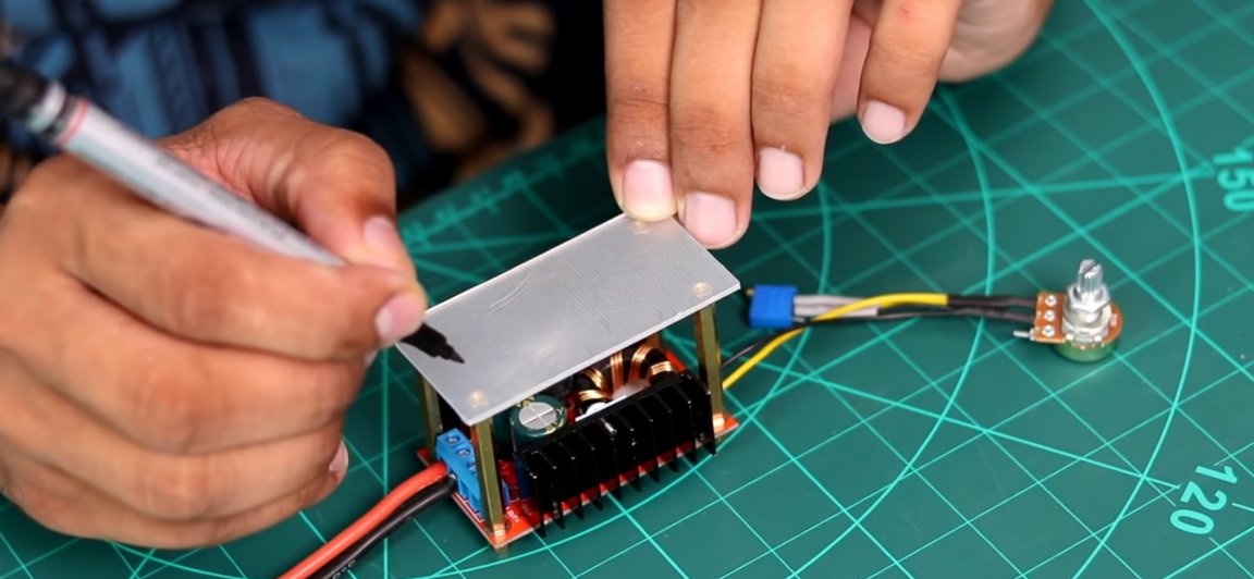
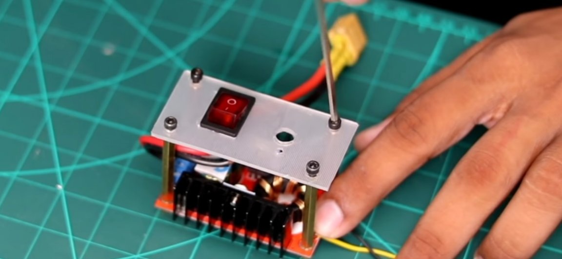
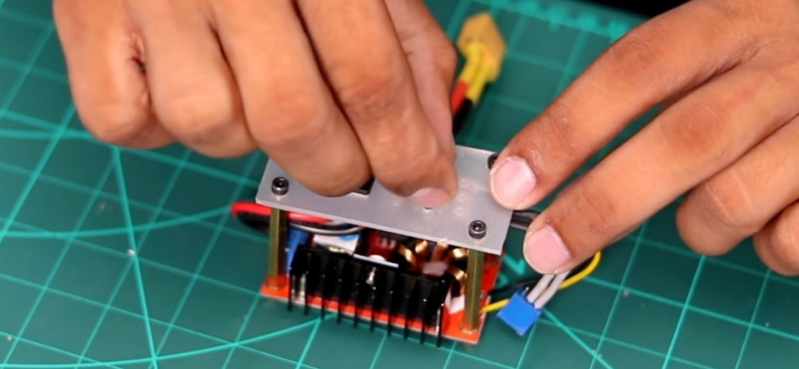
The next step, in order not to damage the elements on the circuit board of the voltage regulator, we should make an impromptu “case”. To do this, in the mounting holes on the board, we fasten the racks for printed circuit boards of such a height that they are higher than all the elements of the board.
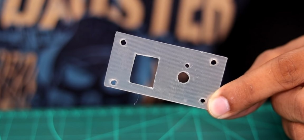
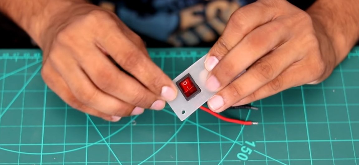
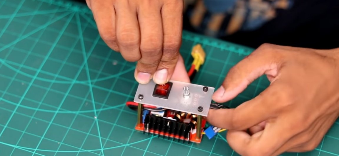
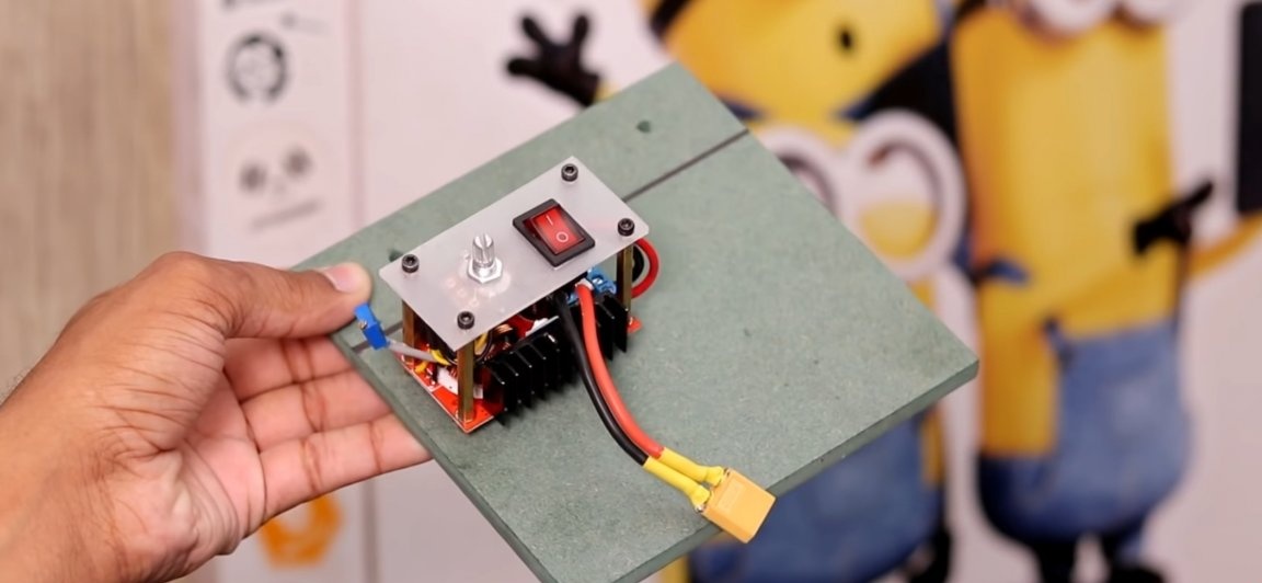
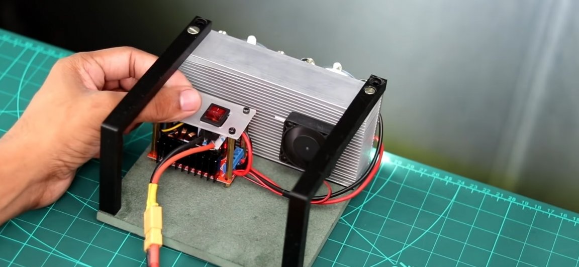
After which we will need to find a small plastic plate, which in the future we will screw to the previously installed racks on the printed circuit board. But before that, on the plastic plate you took, you should make all the necessary holes, namely four fixing holes, one hole for the potentiometer and one hole for the switch.
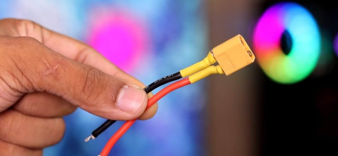
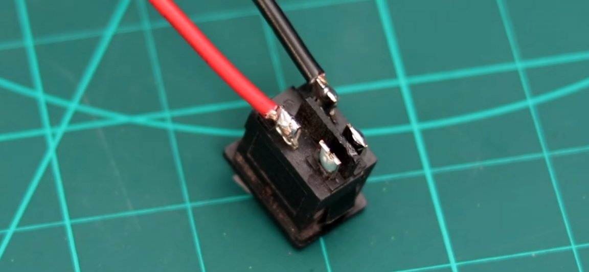
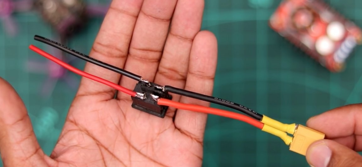
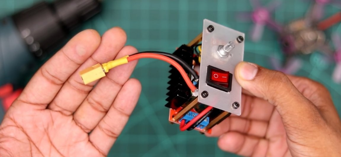
Take the XT-60 connector, solder a couple of wires to it and insulate the bare spots with heat shrink. Solder the other ends of the wires to the switch. Set the switch itself to the plastic plate, for which a hole had previously been made. Then we solder a couple of short wires to the other contacts of the switch, other contacts should be inserted into the “input” of the voltage regulator (observing the polarity!). And finally we screw the plate to the racks on the printed circuit board
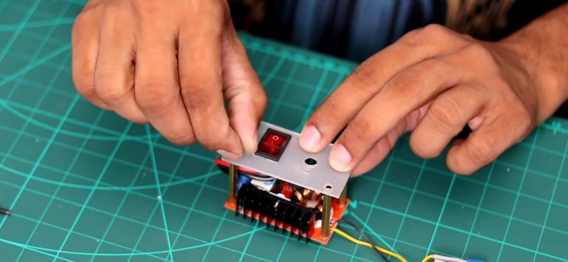
A potentiometer should be installed on the same plate, for this, simply push it through the hole on the back side (having previously unscrewed its nut) and fix it with a nut.
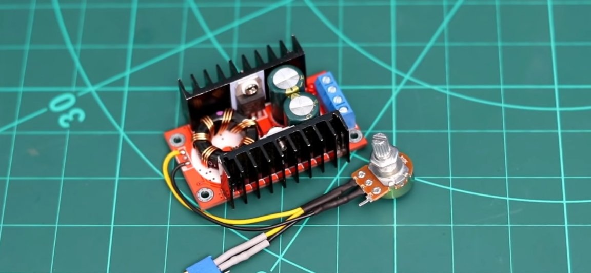
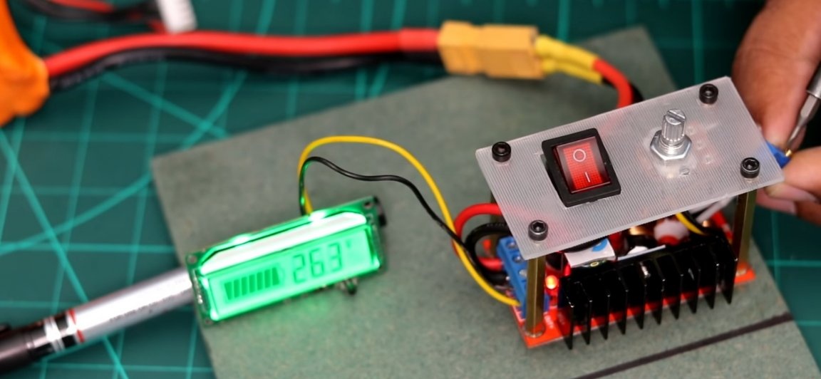
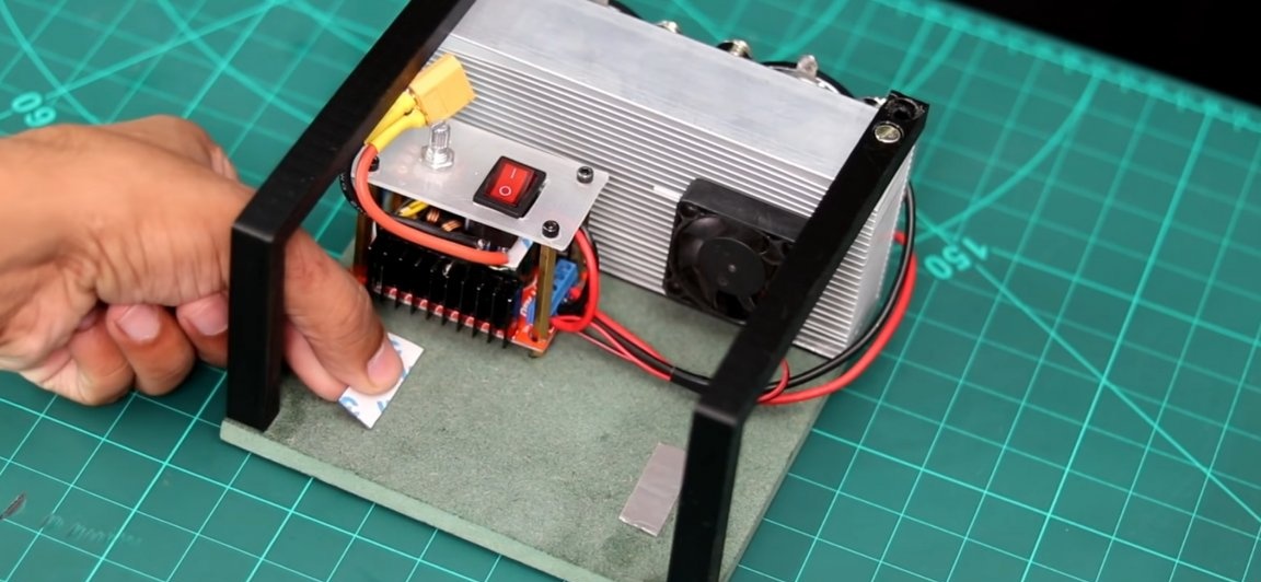
We fasten the already adjusted regulator to the base (MDF panel) to its seat.The next step is to “calibrate”. To do this, connect a voltmeter to the "output" of the regulator, then connect the power. We twist the potentiometer B10K to full and use a screwdriver to twist the stock potentiometer so that the voltmeter has a value of 34-35v, and forget about this potentiometer.
We remove the voltmeter and in its place we connect the LED part. And we fix it to the MDF panel in its place.
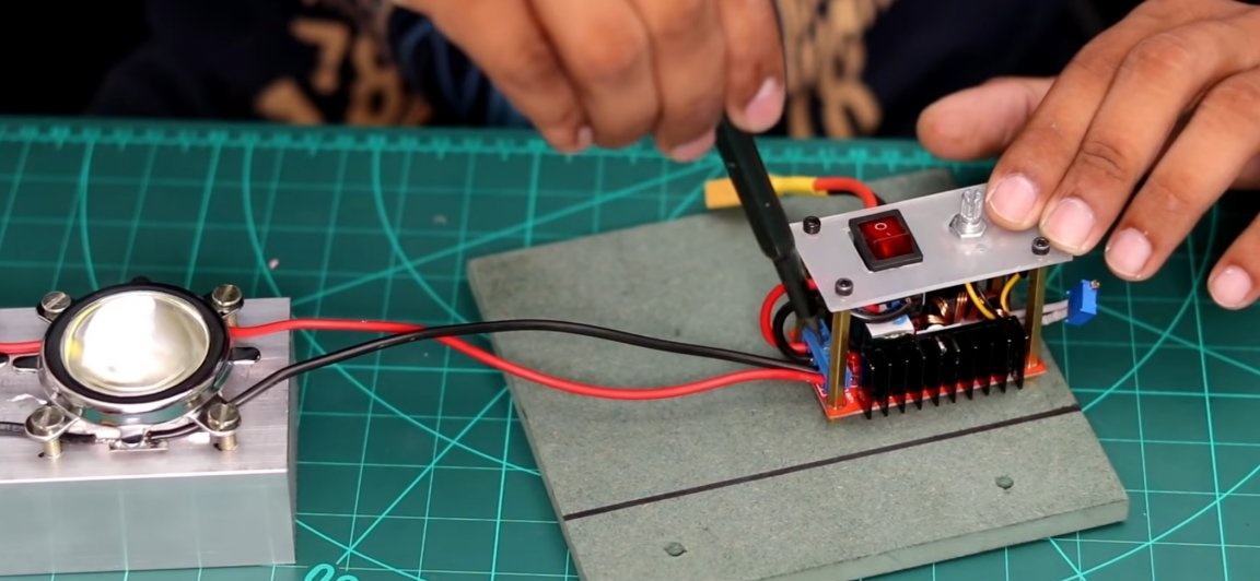
Of course, the radiator could be left without active cooling, but there’s more chance to overheat the LED arrays, so we connect a fan to the “output” on the controller in parallel with the LEDs and fix it with glue to the radiator.
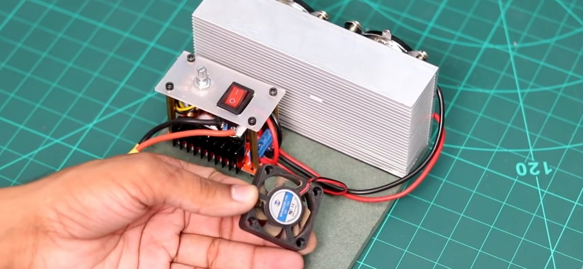
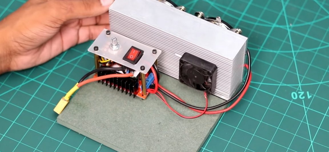
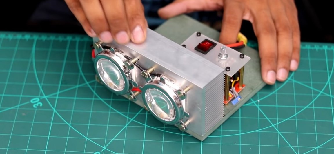
Almost everything is ready, for the next step, the author used a 3D printer for the manufacture of “G” shaped parts to protect components. If you do not have such a printer, you can use the same MDF.
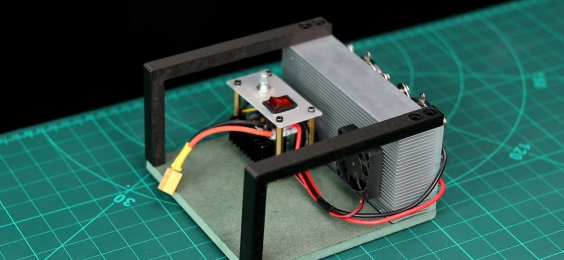
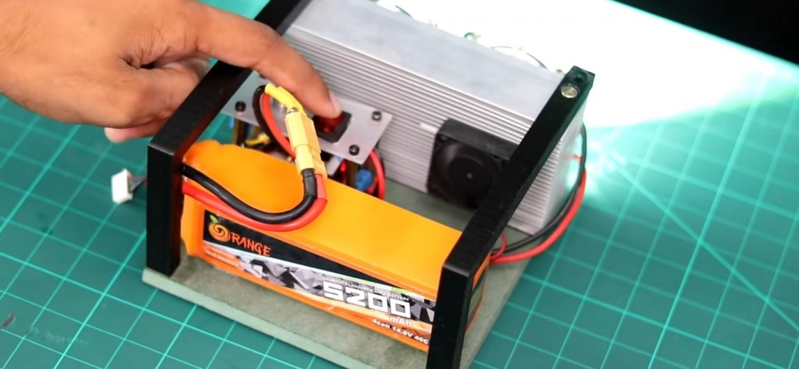
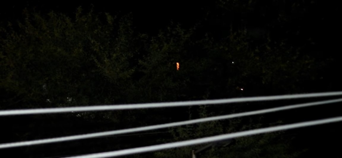
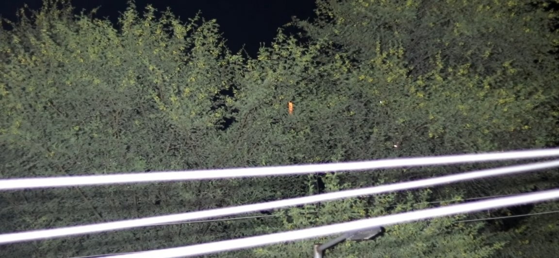
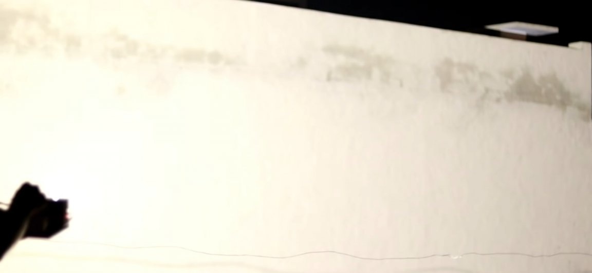
Well, that's all we fix the battery with a double tape to the flashlight and go to test. Photos of the tests you can see below.

You can purchase accessories that can be useful for assembling this homemade product here:
LED Array 100wt
Aluminum heatsink
Voltage regulator
Mount lens
Potentiometers
XT-60 Connectors
Switch
Here is a video of the author of the homemade:
Well, thank you all for your attention and good luck in future projects master