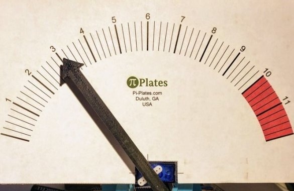
In this article, we will consider how the Master realized his idea of manufacturing a voltmeter using a servomotor.
To make such a voltmeter, the master uses: Raspberry Pi with Raspian and with installed Pi-Plates Python 3 modules, TINKER Pi-Plate, wires, 9G servomotor, thick cardboard, double-sided tape, plexiglass.
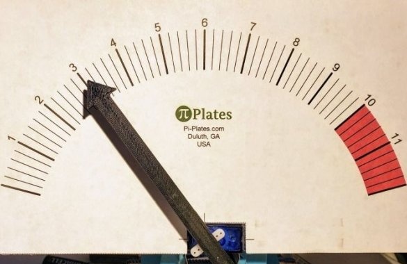
From the cardboard master cuts the arrow.

Or you can print it on a 3D printer. File to print on this the link.
The arrow is fixed to the servo lever with double-sided tape.

From plexiglass cuts the panel.
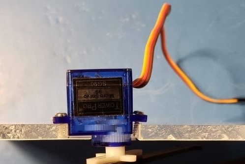
Screws it to the body of the servomotor.
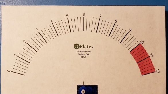
Prints a scale (download the file here).
Sticks a scale to plexiglass.
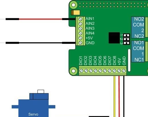
Connects the servomotor to the circuit board according to the diagram. To measure voltage, you need to use wires connected to GND and AIN 1.
Next you need to calibrate the voltmeter.
Includes Raspberry Pi. Creates a Python3 session, loads the TINKERplate module, and sets the digital I / O channel 1 mode to “servo.” Now the servo should move to 90 degrees.
Next, sets the arrow of the voltmeter to 6V.
Enters TINK.setSERVO (0,1,15) to move the arrow to position 0V.
Enters TINK.setSERVO (0,1,165) to move the servo to position 12V.
If the arrow deviates from the given readings, you need to adjust the values 15 and 165
Next, you need to download the code.
import piplates.TINKERplate as TINK
import time
TINK.setDEFAULTS (0) #return all ports to their default states
TINK.setMODE (0,1, 'servo') #set Digital I / O port 1 to drive a servo

lLimit = 12.0 #The lower limit = 0 volts
hLimit = 166.0 #The upper limit = 12 volts

while (True):
analogIn = TINK.getADC (0,1) #read analog channel 1
#scale the data to an angle in the range of lLimit to hLimit
angle = analogIn * (hLimit-lLimit) /12.0
TINK.setSERVO (0,1, lLimit + angle) #set servo angle
time.sleep (.1) #delay and repeat
All is ready.

