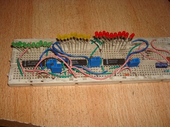
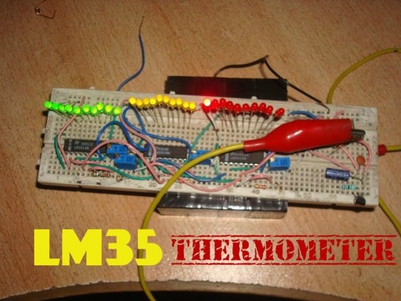
A thermometer with a scale indicator, proposed by Instructables under the nickname badarsworkshop, is intended for indoor use. On a scale of 30 LEDs, it displays temperatures from +10 to +39 ° C.
The master was able to build such a device without a microcontroller on two types of microcircuits. The LM35 is a temperature sensor with an analog output. If the voltage in millivolts at this output is divided by 100, you get the temperature in degrees Celsius. So everything is simple and clear. And this rule is observed in the temperature range from 0 to 100 ° C. The measurement accuracy of 0.25 degrees at room temperatures and 0.75 in the entire range makes the microcircuit unsuitable for medical thermometers, where a division price of 0.1 ° C is needed. You can only roughly find out whether the temperature is normal or elevated, as with a device on thermochromic dyes, but nothing more. But to measure the temperature of the air in the room such accuracy is more than enough. There is a similar sensor LM34, characterized in that it measures the temperature in degrees Fahrenheit. Well, LM3914 is the simplest ADC, the output of which is presented not in binary code, as it usually happens, but in positional. Since one such converter can control 10 LEDs, three microcircuits had to be used to get a range from +10 to +39 ° C with a division price of 1 ° C.
The thermometer circuit is shown below, as can be seen from it, the inputs of all three ADCs are connected in parallel, only the measurement limits are set differently with multi-turn tuning resistors.
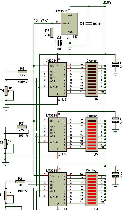
And these are the pinouts of the applied microcircuits:
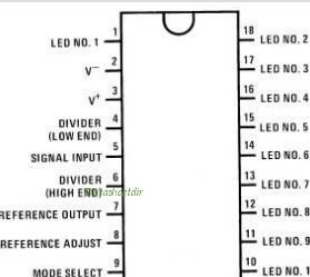
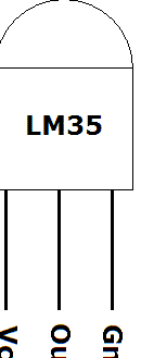
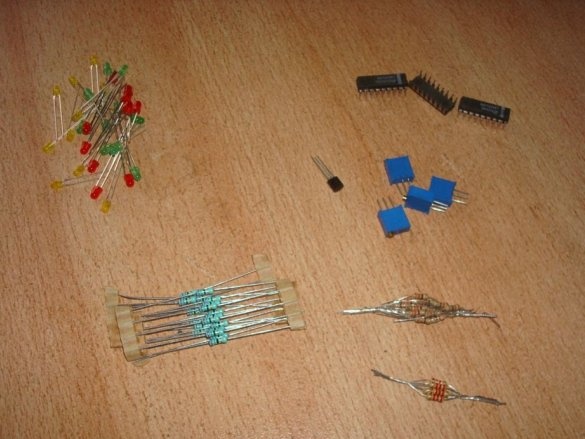
The wizard prepares the components necessary for assembling the thermometer:
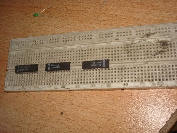
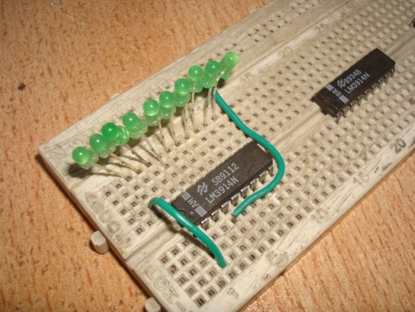
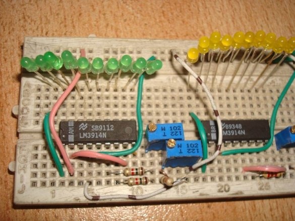
And begins to collect. He puts all three ADC chips on a breadboard like breadboard (if you have soldering skills):
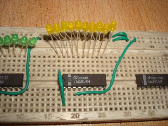
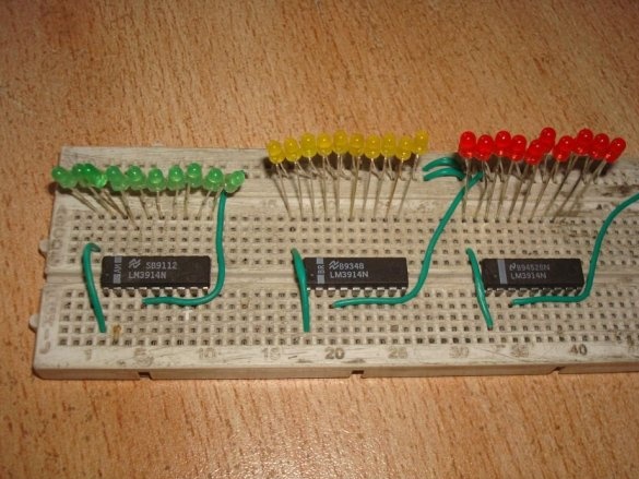
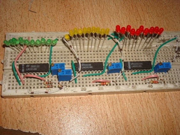
Then - LEDs and jumpers. According to the translator, a monochrome scale will look better, but the master thinks differently. There are few jumpers required, since the pinout of the microcircuits almost matches the position code. But almost does not mean at all.
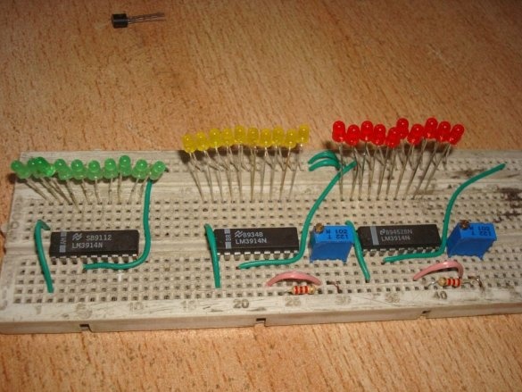
It is the turn of resistors - constant and multi-turn tuning:
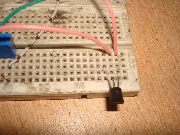
Following them, the master installs a temperature sensor with a strapping - a resistor and two capacitors, one of which is polar. If desired, you can make the sensor remote.
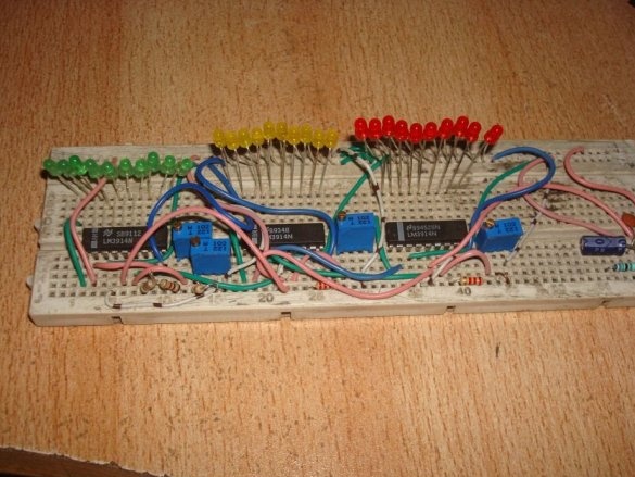
The wizard adds a diode to protect the circuit from polarity reversal of the power supply (not shown in the diagram) and a few more jumpers:
For those who want to transfer the circuit to a printed circuit board, the master leads archive link. And on the original projectwhere the device is made on such a board and with the use of scale indicators. But the master decides to leave it that way on the breadboard. It is also possible, but it is very desirable to come up with some kind of case in any case.
Many are used to analog electronic Thermometers must be set up by placing the temperature sensor in melting ice or in boiling water. This is not required here, since a sensor with a known and linear characteristic is used. It is more accurate to set the voltage adjusters indicated on the diagram next to them on the moving contacts of the tuning resistors. And periodically check whether they crawled away. At precisely set voltages, the thermometer measures the temperature correctly.

