The author of Instructables under the nickname frapedia designed and manufactured do it yourself a simple device for checking the health of servos, often used in conjunction with Arduino. At the heart of homemade - microcircuit 4001 (K561LE5).
The master compiles the documentation for the homemade product, consisting of four parts:
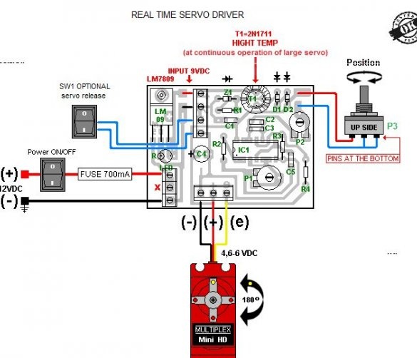
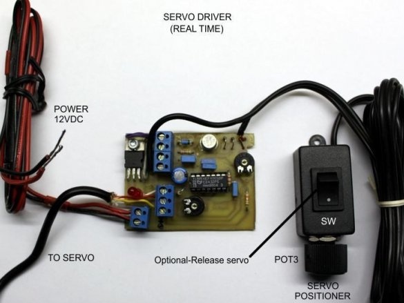
1. The scheme combined with the board pattern:
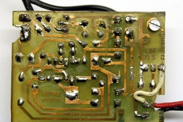
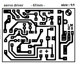
2. Board drawing separately:
3. Table of types and ratings of components:

The table is compiled in two versions: for small and medium-sized servo drives, as well as for large ones. The stabilizer requires a heat sink in any case, and the transistor is only an option for large servo drives. The resistances of the tuning and variable resistors are listed separately:
P1 - 220 kOhm
P2 - 47 kOhm
P3 - 100 kOhm
This is not a typo, here the constant resistors are designated as R, and the trimmers and variables are indicated as P.
4. The pinout of the applied transistor:
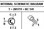
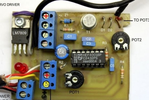
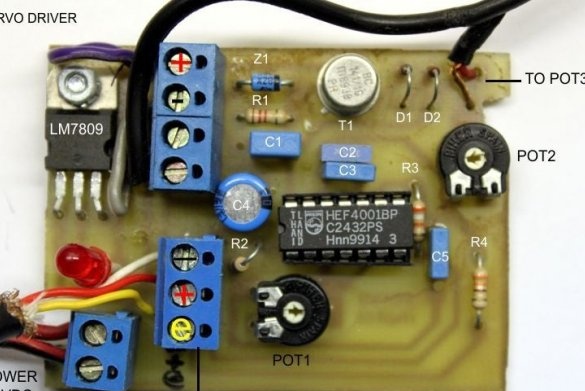
Having decided on the components and the circuit, the master makes a board and assembles it:
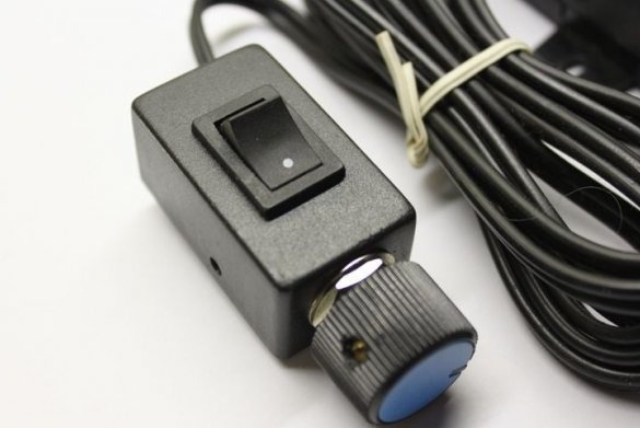
It places a variable resistor and a switch in the common case, which allows you to turn off the servo drive, while it becomes possible to turn it with an external force:
Everything connects:
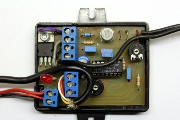
And installs the board itself into the case:
When the variable resistor rotates, a serviceable servo without jerks proportionally rotates in the same direction. If in the opposite, you need to swap the side terminals of the variable resistor. If the jerks are the same with any servos - change the variable resistor, clean it, or restore graphite spraying in it. The device is compatible with servos without limiting the angle of rotation, as well as with its limitation to 90 and 180 °.

