
The laboratory power supply is one of the main devices of the amateur radio laboratory. Today we will collect and check an interesting diagram. The option given in this article is quite popular on the open spaces of the World Wide Web under the name of a simple and affordable power supply.
This scheme is reserved for a separate forum thread, it was developed by a person under the nickname "olegrmz".

The scheme has been repeatedly refined and currently there are a total of about a dozen different variations and modifications. As an example, we will make the very first version from the author. Further instructions are taken from the AKA KASYAN YouTube channel.
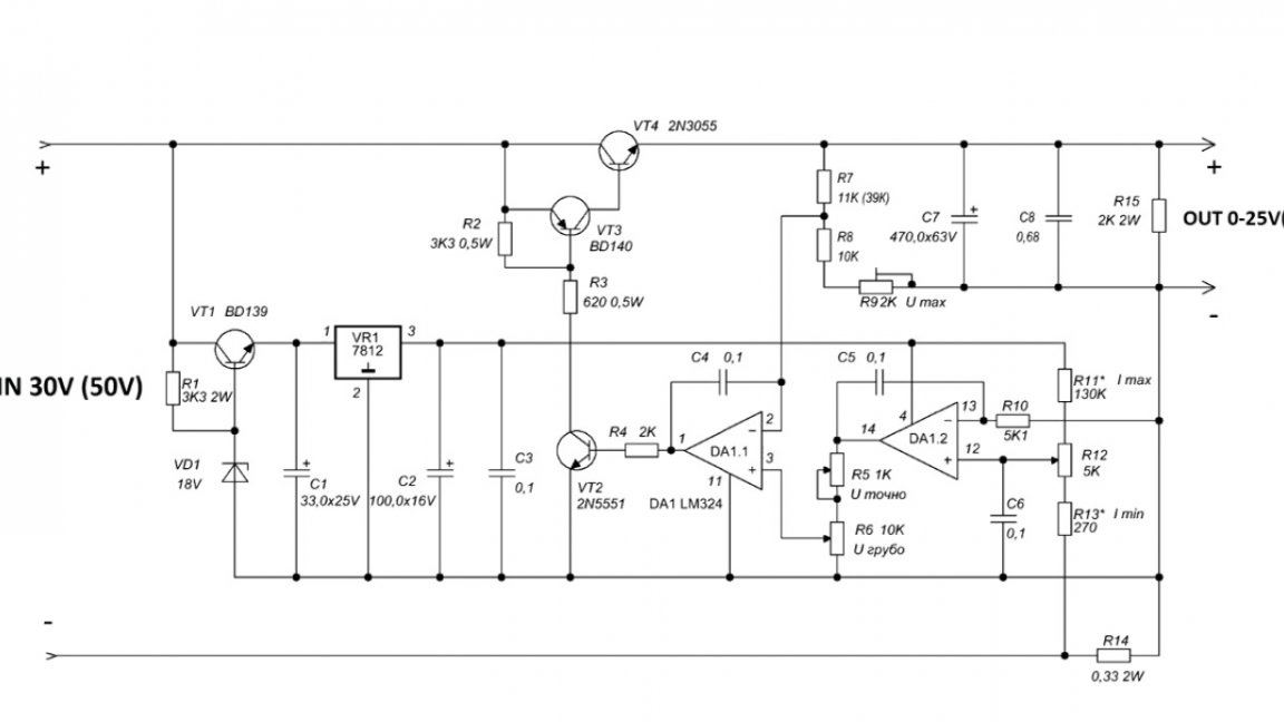
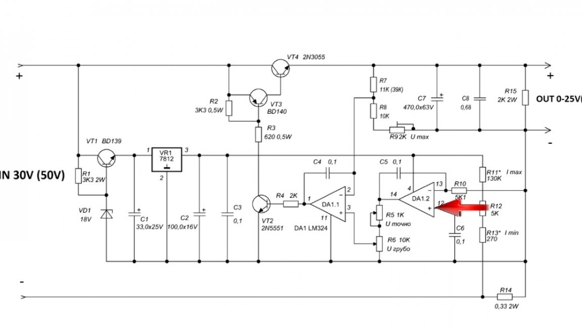
A few words about the scheme. In fact, it is a full-fledged laboratory power supply with stabilization both in voltage and current. The range of adjustment of the output voltage is from 0V to 25V, the current is practically from 0 to 1.5-2A.
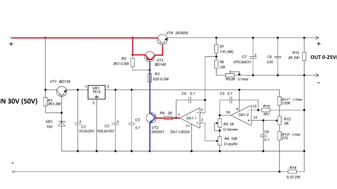
If necessary, the output voltage of this power supply can be made up to 50V:
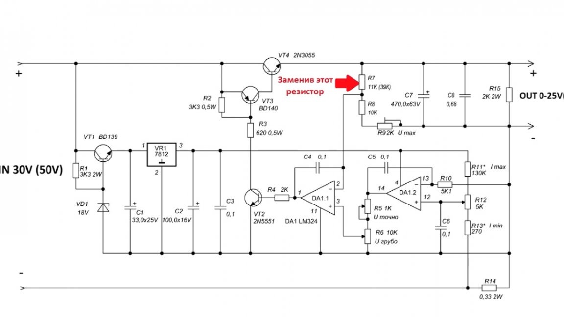
And the current is at least 10A. To do this, add power transistors.
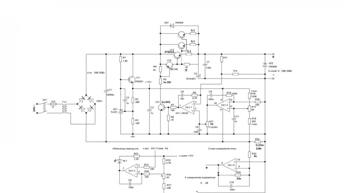
The circuit works completely in linear mode, provides a very smooth adjustment of both voltage and current. There are practically no ripples in the output voltage.
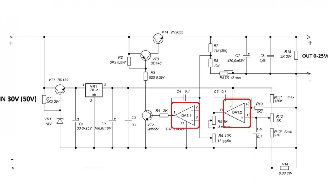
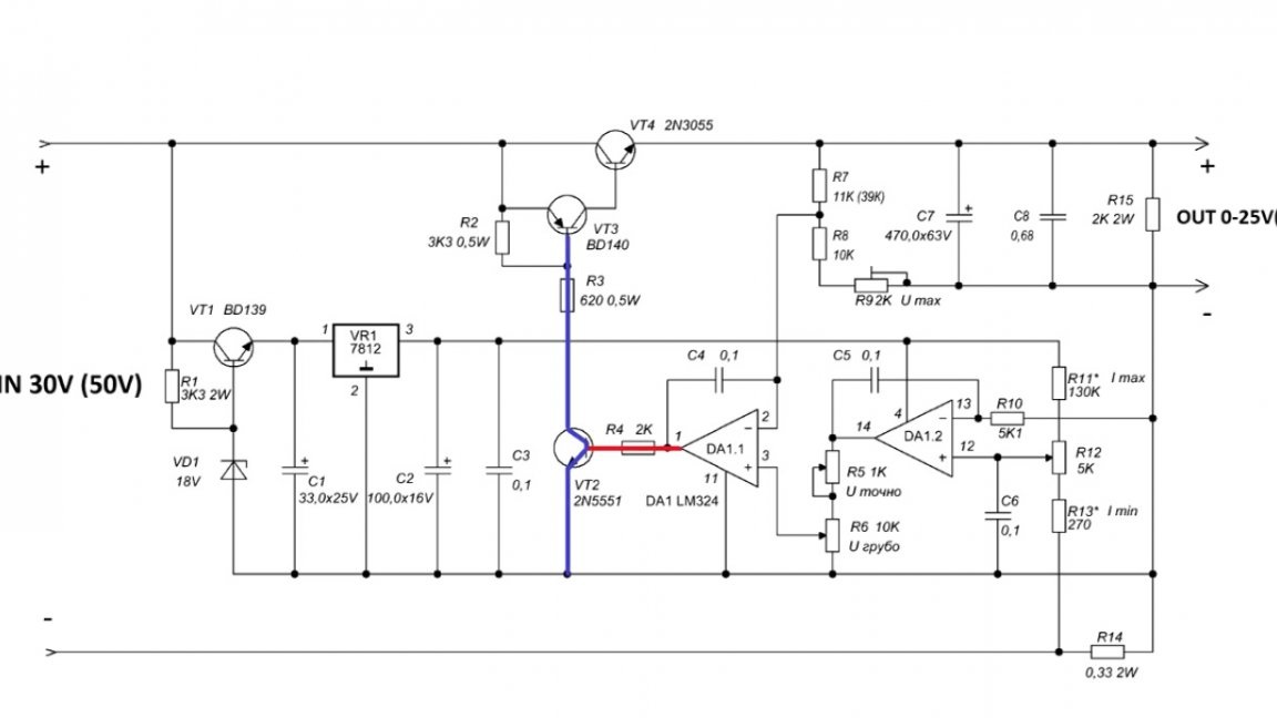
The heart of the circuit is a dual operational amplifier.
On the left side of the circuit is a voltage regulator.
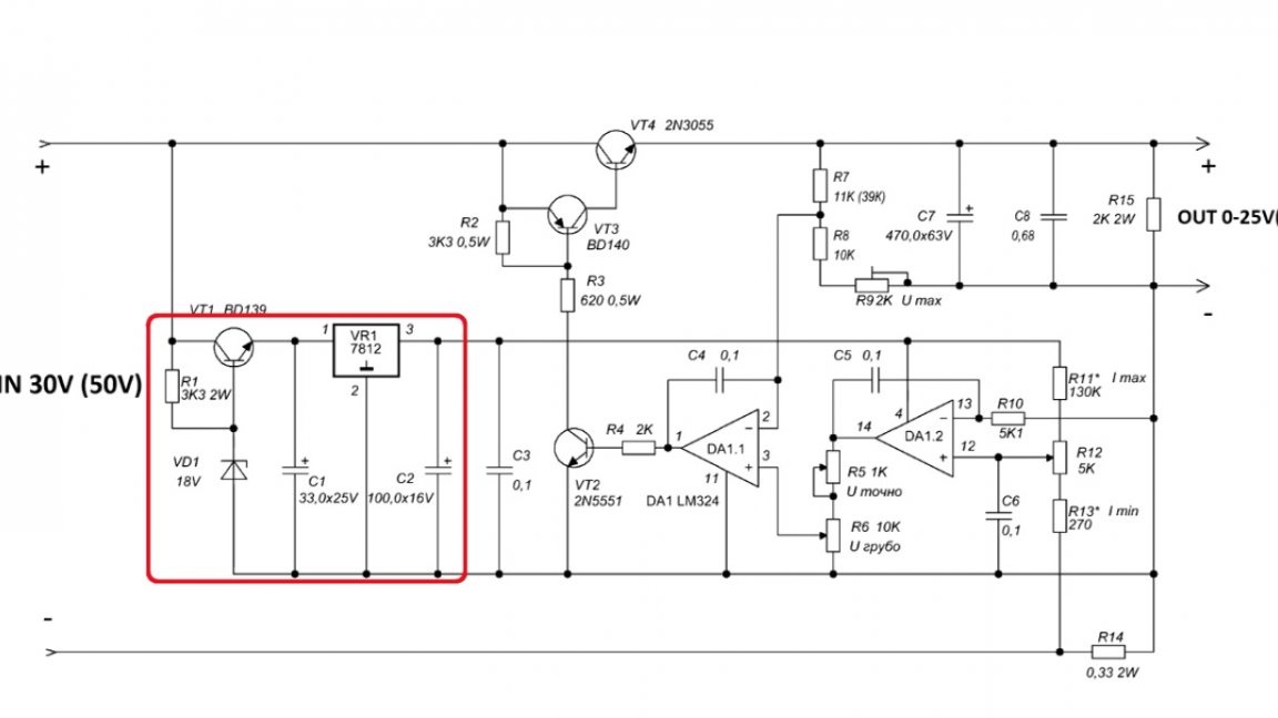
Moreover, as you can see, there are two whole voltage stabilizers.
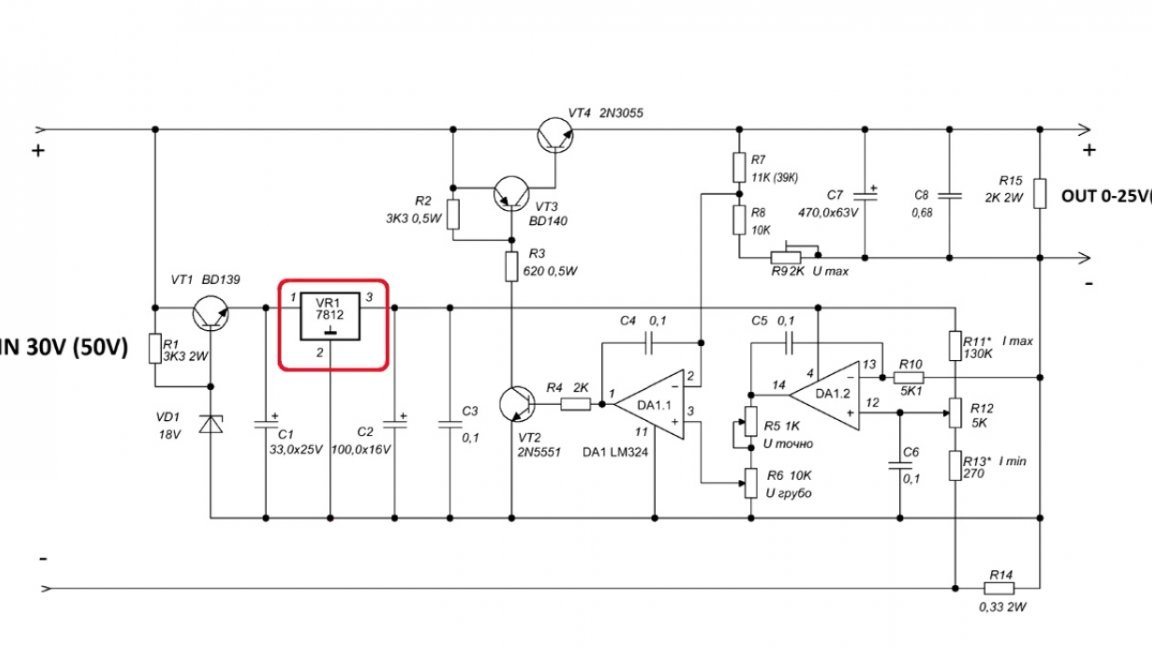
The question arises: why is this necessary and why not be limited to one? The second stabilizer is 12V, and quite good, but the problem is that it can supply no more than 30-35V to its input, but the first quietly digests higher voltages, but its output voltage does not shine with stability. In this case, one stabilizer seems to cover the shortcomings of another. During operation, they almost do not heat up, since they only power an operational amplifier, the current consumption of which is small.
The operational amplifier is powered by a second 12V voltage stabilizer, in the original circuit an lm324 chip is used, which includes 4 opamps.
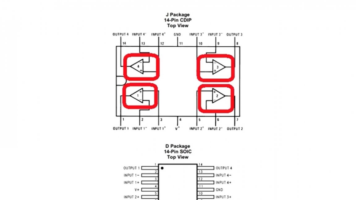
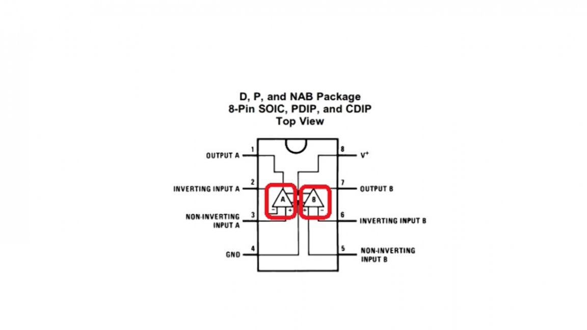
But since we have only two channels involved in the circuit, it was decided to replace the operational amplifier with the lm358 chip, it contains just 2 independent opamps.
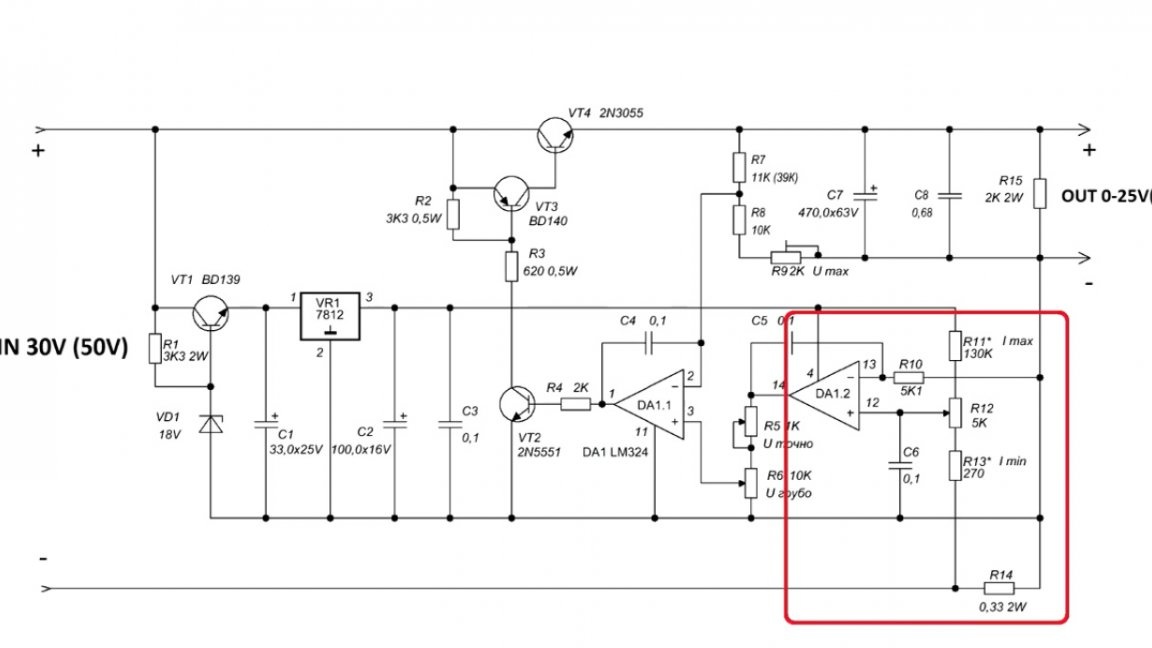
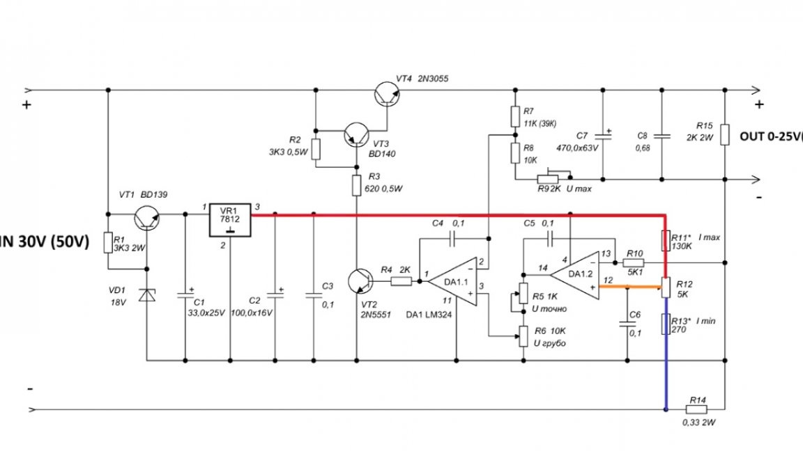
This circuit is also interesting in that the current feedback controls the output voltage.
When the power source operates as a voltage stabilizer, the first operational amplifier operates as a comparator and provides a stable output voltage, which is the reference for the second amplifier, on which voltage regulation is built.
The current limiting system is classic.
A reference voltage is applied to the non-inverting input of the first operational amplifier through a divider.
Further, when the load is connected, the voltage drop that will form on the current sensor is compared with the reference one. Based on the difference in the output state of the operational amplifier changes smoothly.
By forcibly changing the reference voltage using a variable resistor, we actually force the operational amplifier to change its output voltage, which ultimately leads to a smooth opening or closing of the power transistor and a change in the output current of the power source.
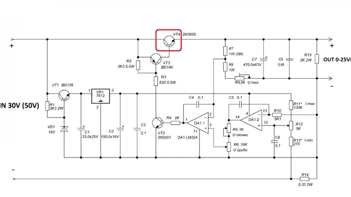
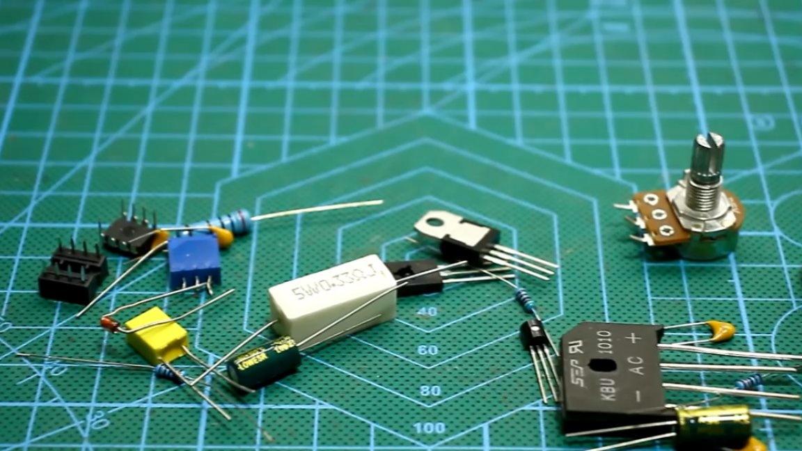
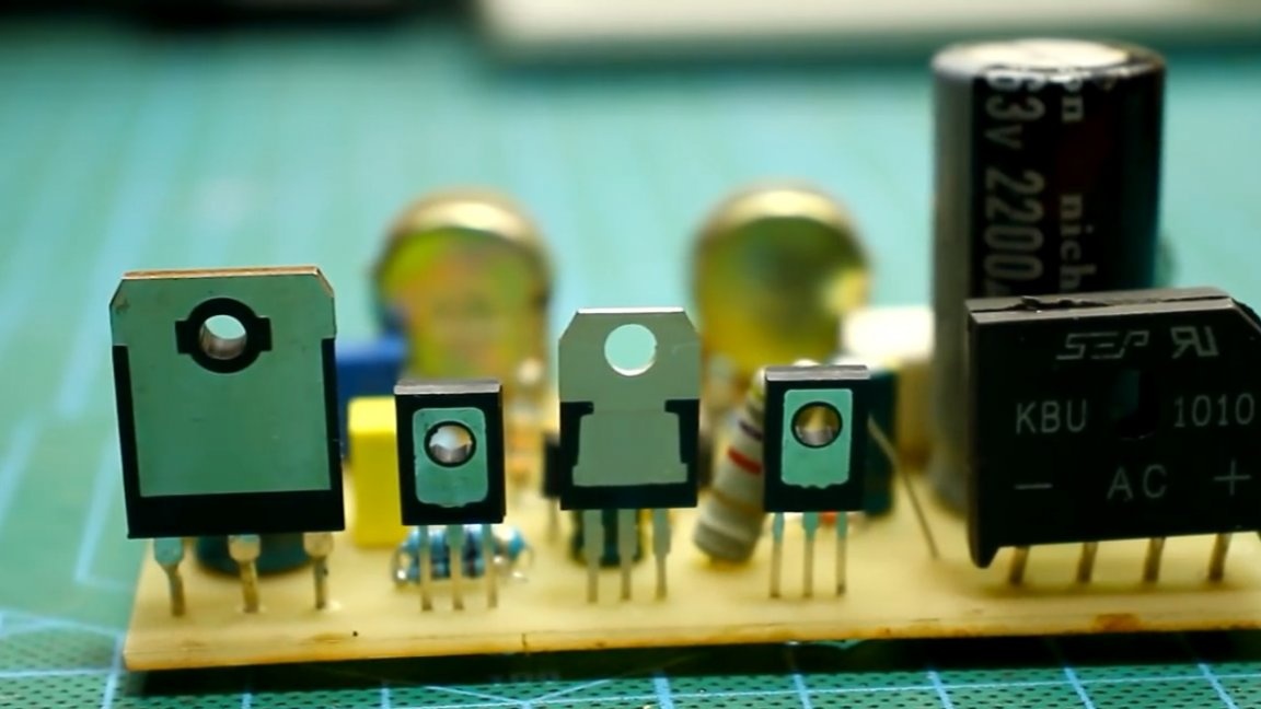
Power transistor. In a specific example, the author used 2SD1047.
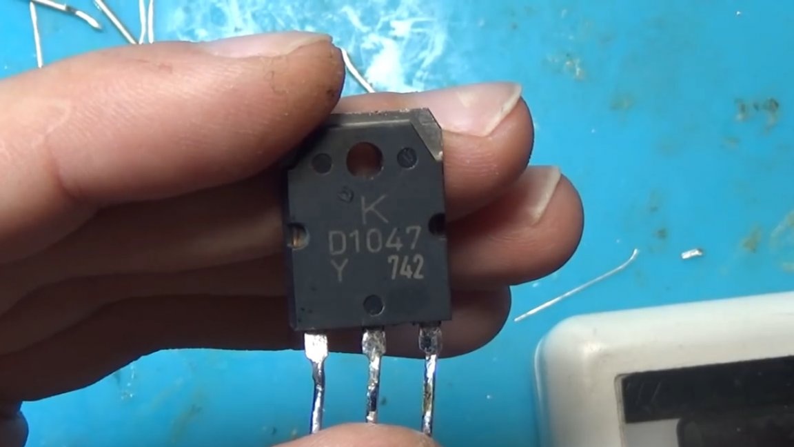
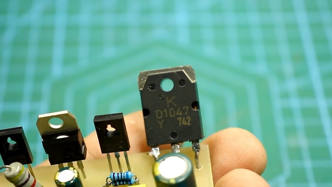
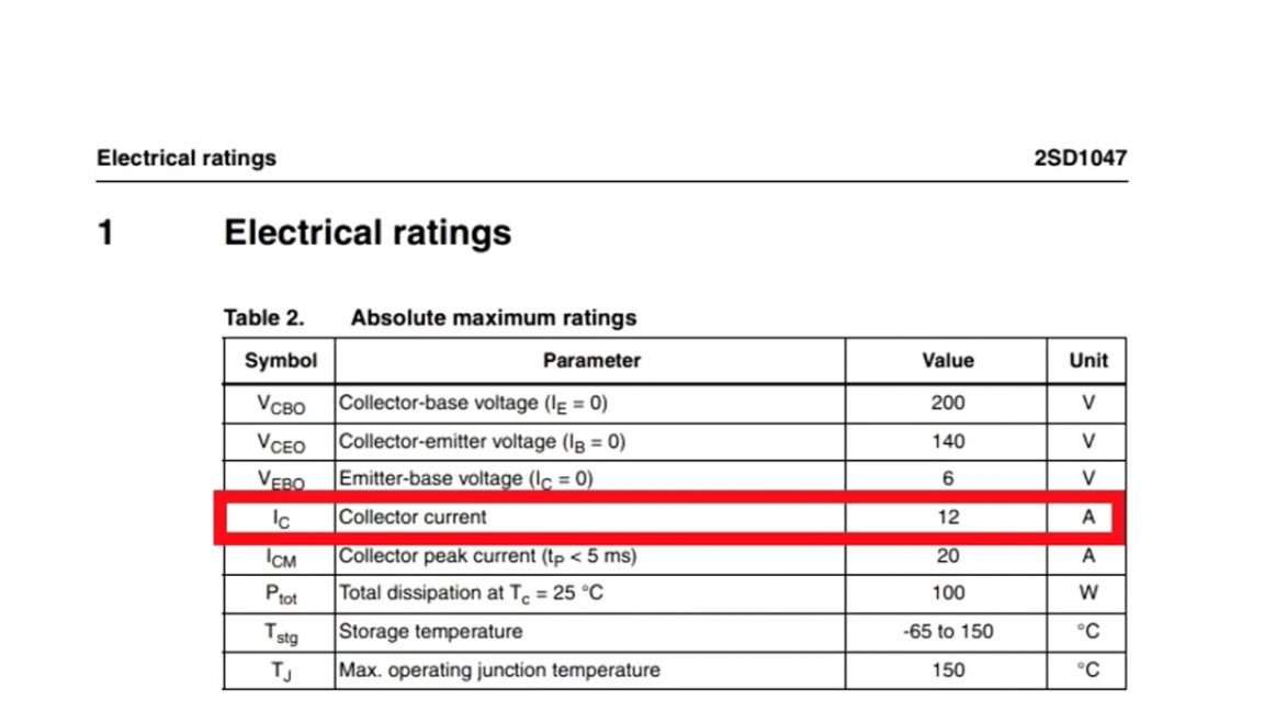
It is quite high voltage, the collector current is 12A.
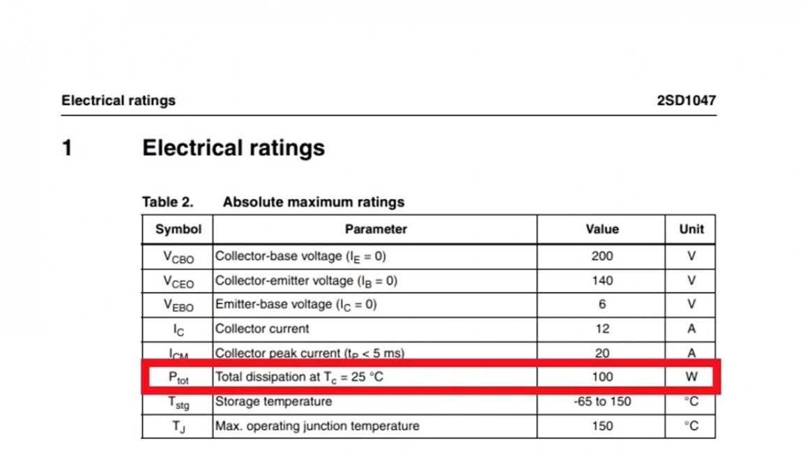
And the power dissipated by the collector is about 100W.
The power transistor can be replaced by any other similar to the collector current from 7A, it is also desirable to use transistors in the TO-247 or TO-3 package.
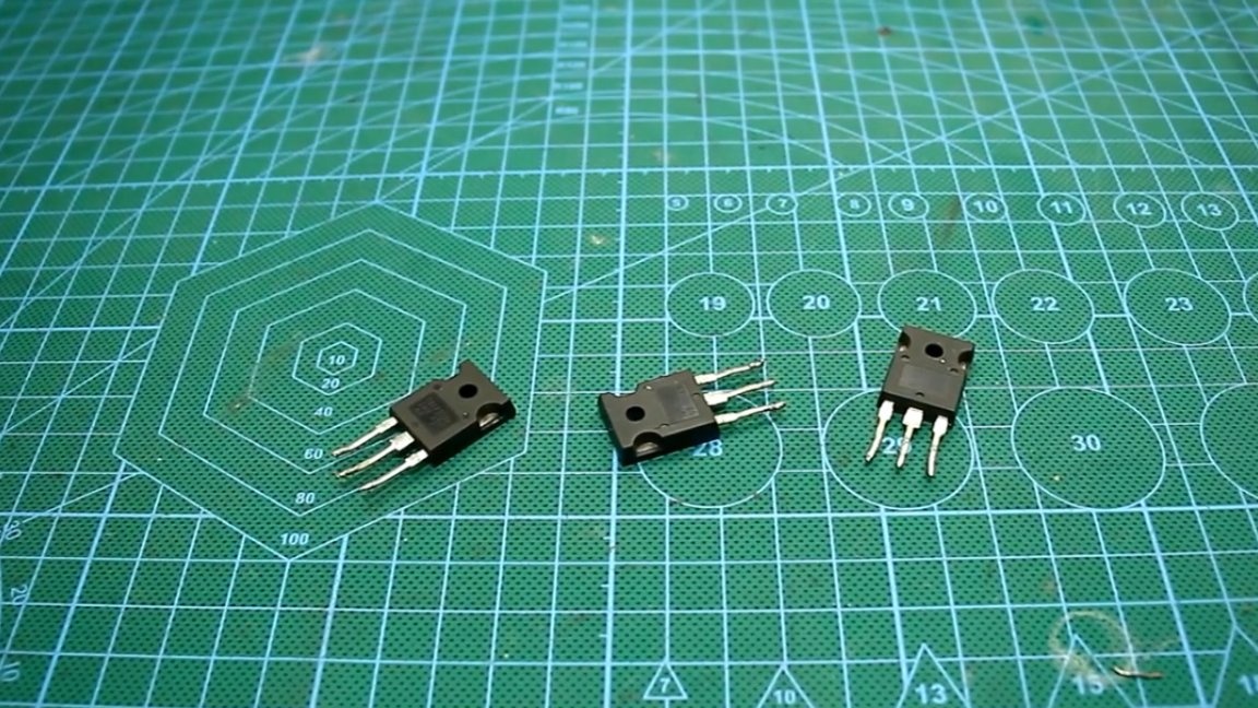
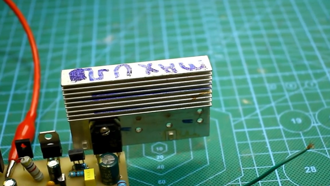
The circuit operates in linear mode, so the transistor must be installed on a massive radiator, you may need additional airflow. The radiator that the author uses is quite small, a radiator is much more needed here.
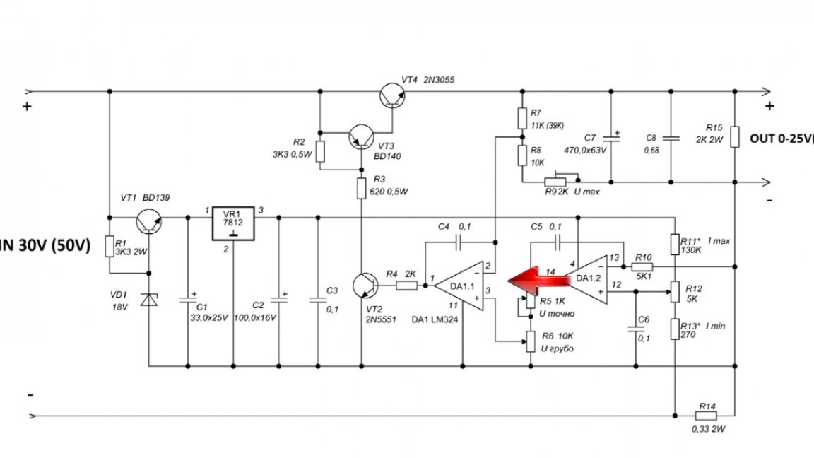
The signal from the operational amplifier is inverted by a low-power transistor and fed to the pre-output key, which actually controls the output transistor.
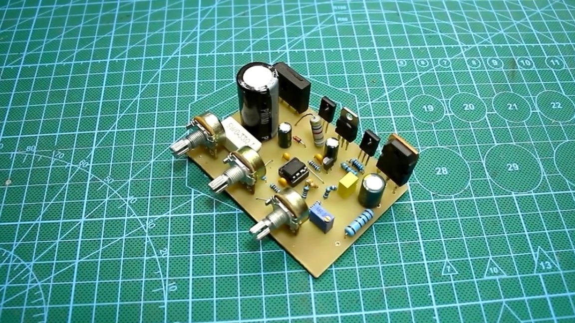
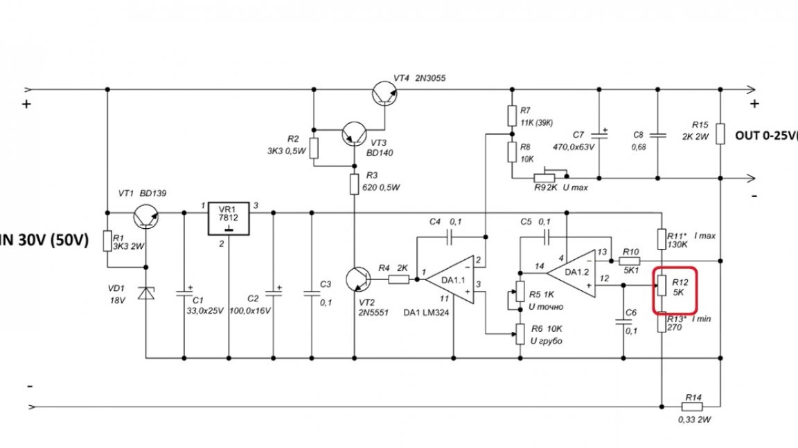
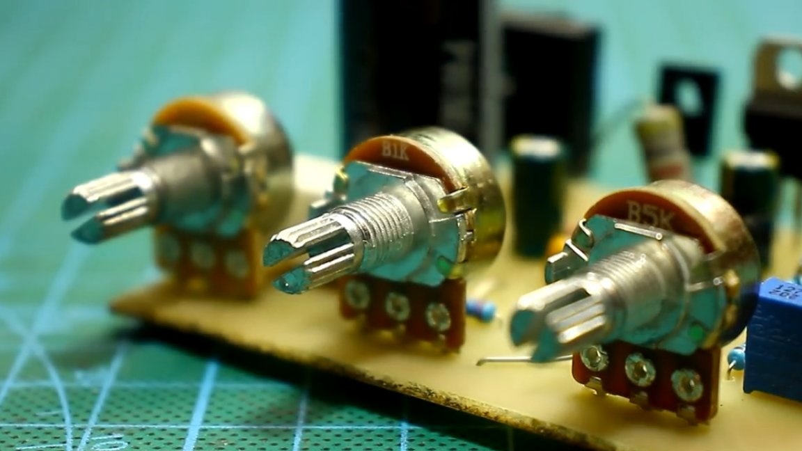
The circuit has 2 variable resistors. They are necessary for smooth and precise adjustment of the output voltage.
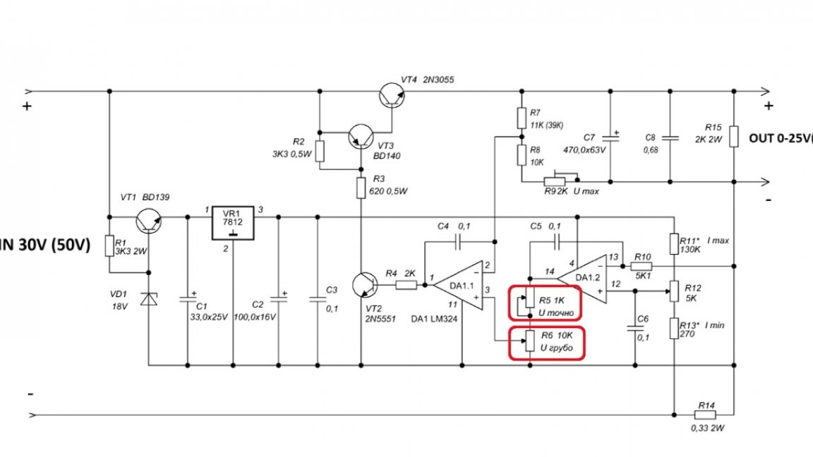
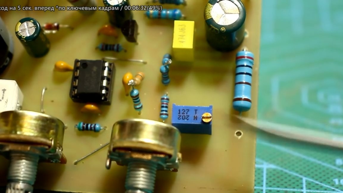
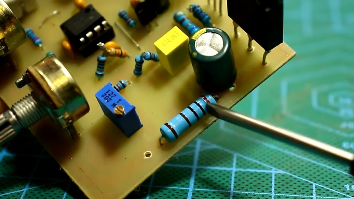
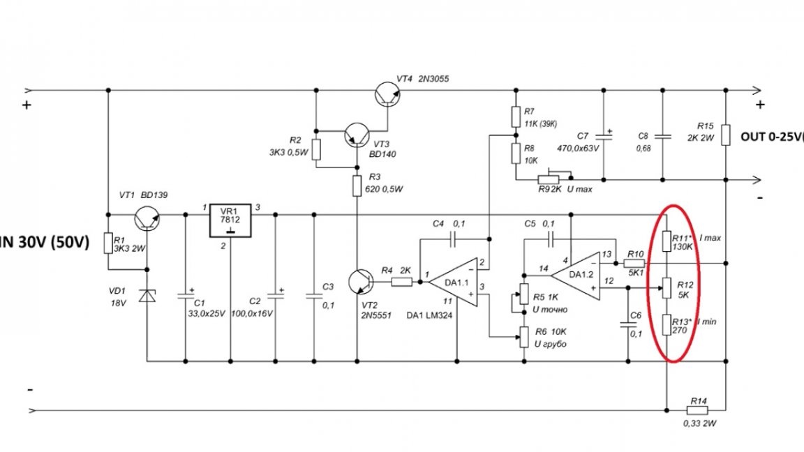
A full revolution of the fine-tuning resistor allows for voltage adjustments ranging from about 3V. The image below shows a resistor that sets the output voltage limit.
There are 3 jumpers on the circuit board. It would be possible to do without them, but the author was in a hurry during the board layout, in general, it could have been better, but nonetheless, the board is fully operational. You can download it along with the general project archive on this link.
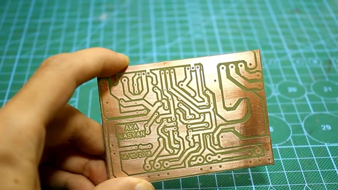
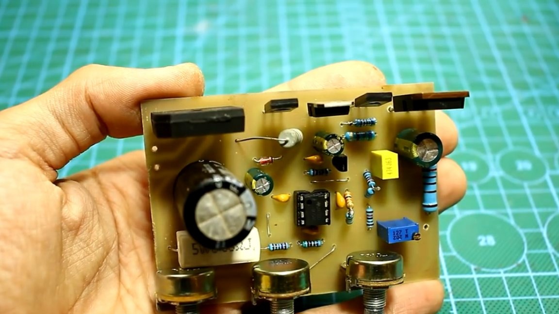
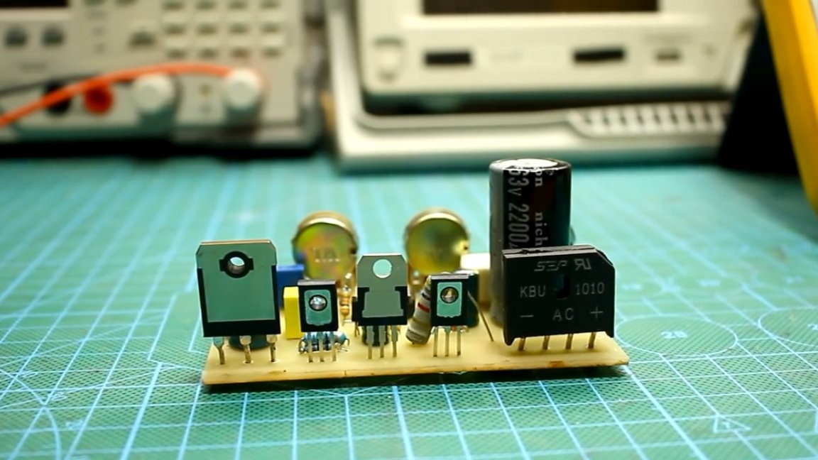
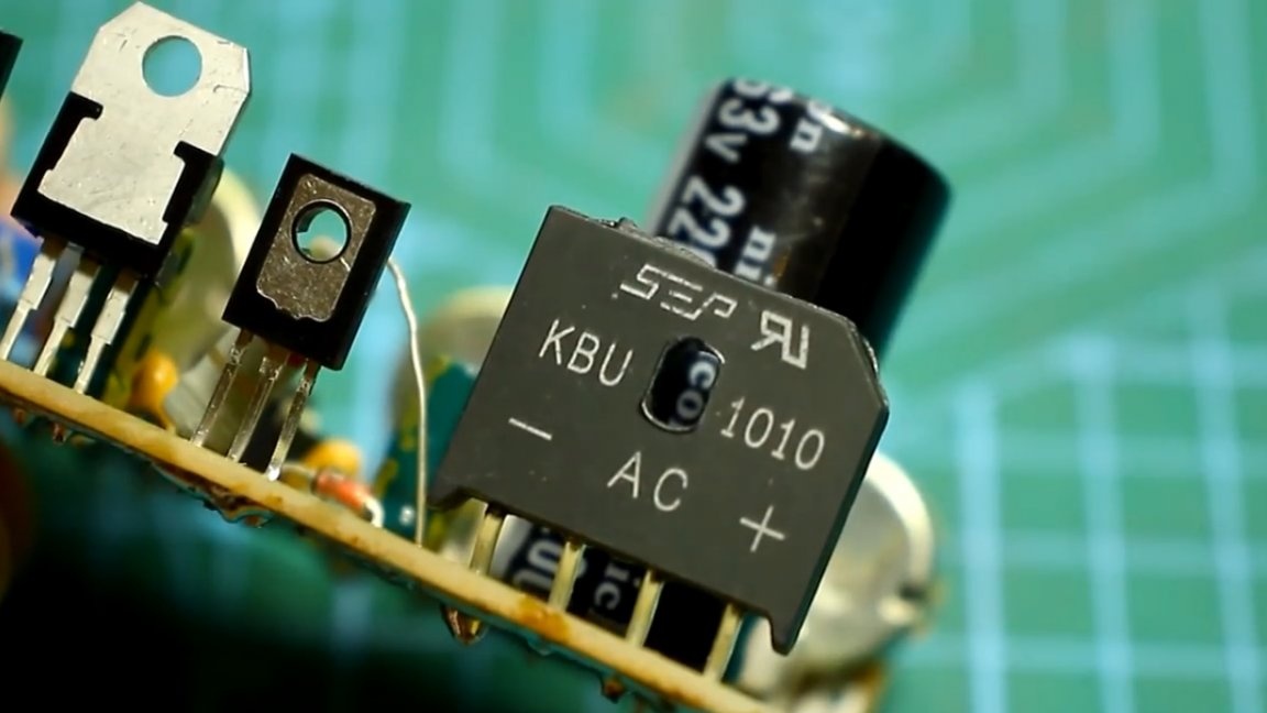
A rectifier with an electrolyte for power is provided on the board.
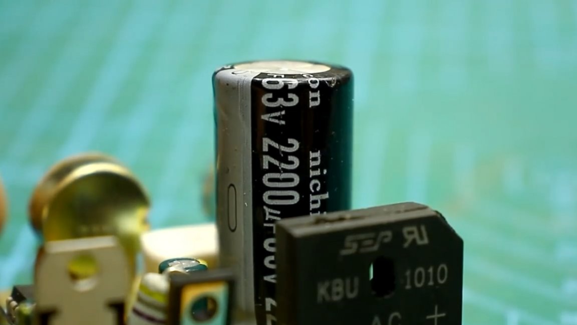
All power components that will heat up during operation are located nearby. This is necessary for ease of installation on a common radiator. Moreover, it is necessary to isolate all components from the radiator case with special heat-conducting gaskets and plastic bushings.
An input rectifier with a current of 4-5A, but it is desirable to supply a 10-ampere electrolyte at 50-63V with a capacitance of 2200uF.
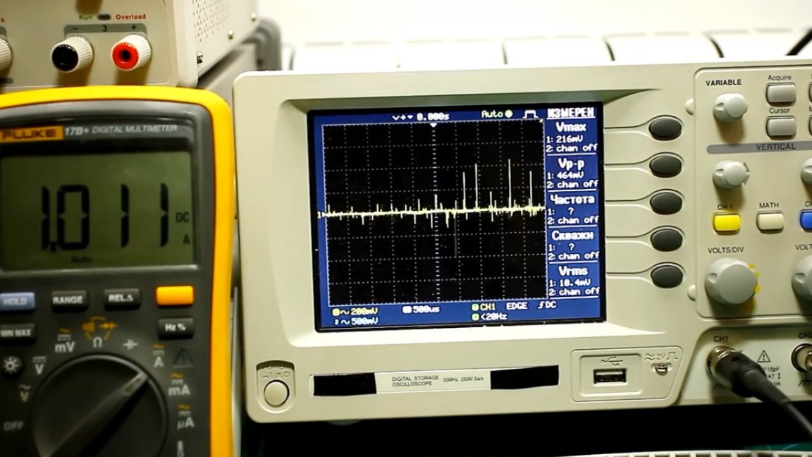
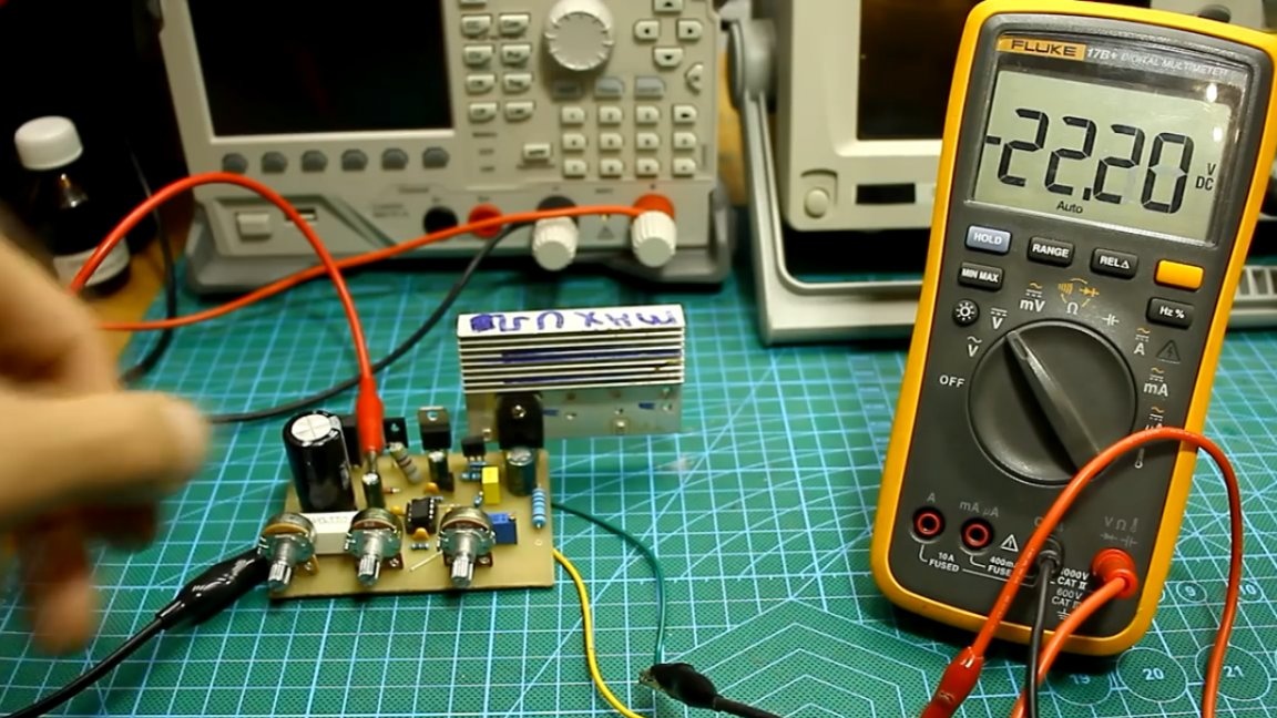
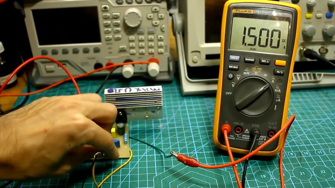
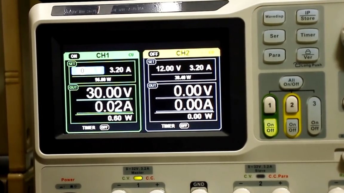
Let's start the tests. Let's start with a simple one - smooth adjustment of the minimum output voltage. The input is 30V, the maximum output voltage is about 23V, the minimum voltage is zero, the adjustment is very smooth, you can set at least 10mV.

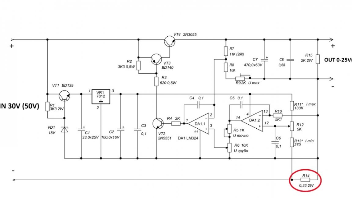
The current consumption of the stabilizer without a load is about 10-20mA, but this will directly depend on the output voltage, since there is a load resistor at the output.
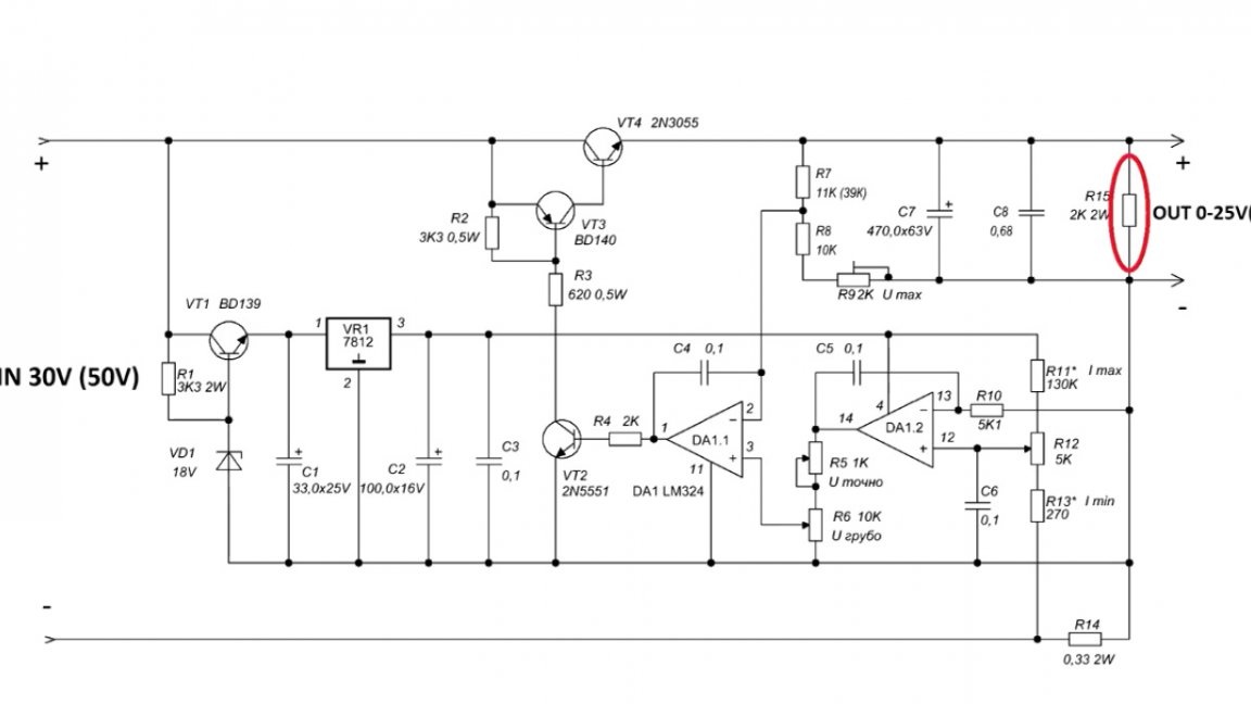
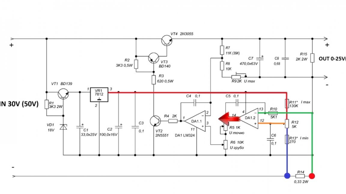
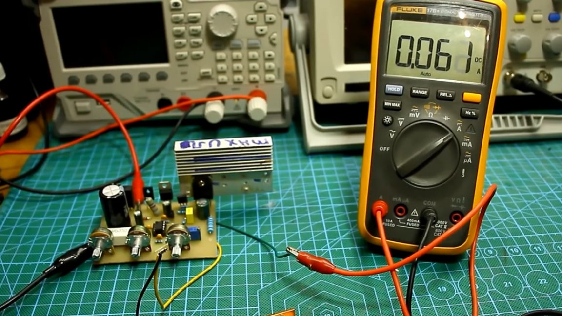
There are no complaints about limiting the current, everything works as it should. Under load, the current is regulated with sufficient smoothness. The upper limit is about 1.5A, the lower - 60mA, but playing with the appropriate divider (see image below) can be done even less.
Now the cons of this power supply. The problem is this: if you try to short-circuit the unit at the minimum current, then the current is not limited, and if the transformer is powerful, then you can say goodbye to the power transistor.
But it is worth noting that in subsequent versions the scheme has been finalized and this problem has been completely resolved.

But at maximum current, everything works clearly, with a short circuit, the unit copes perfectly.
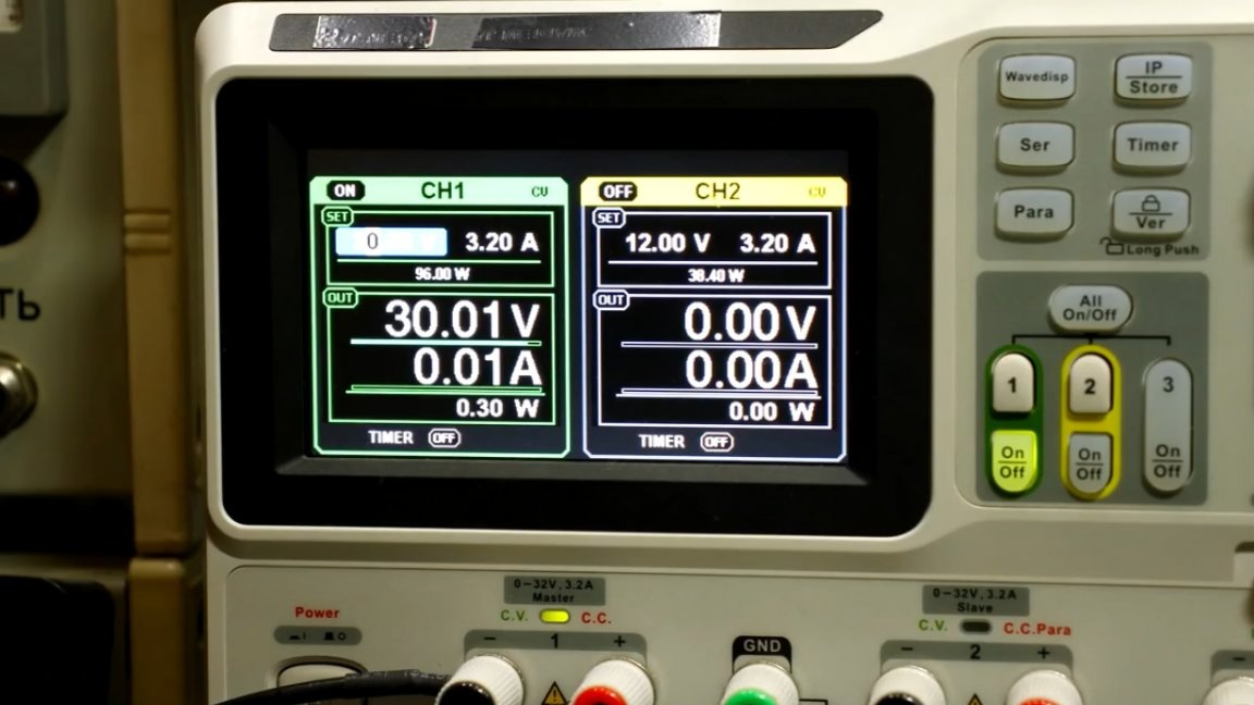
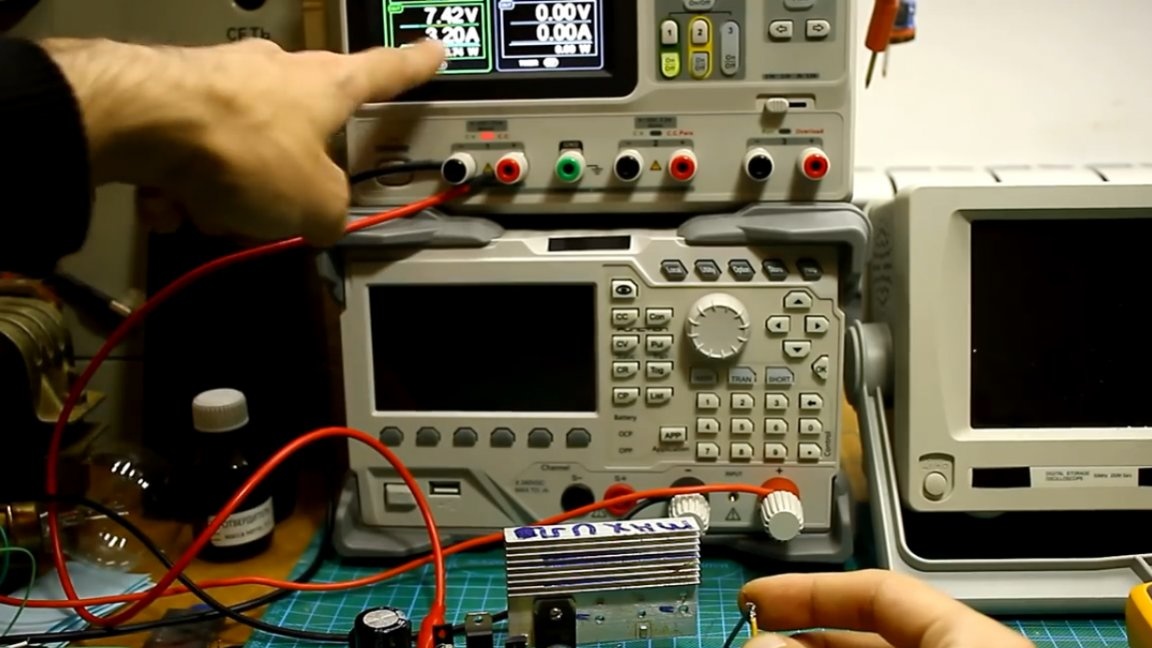
Next test - checking the operation of feedback, in other words - stabilization during sudden surges and drops in mains voltage. We will simulate voltage drops by another laboratory power source, which, in fact, will power our stabilizer. The output voltage of the stabilizer is set to 12V.
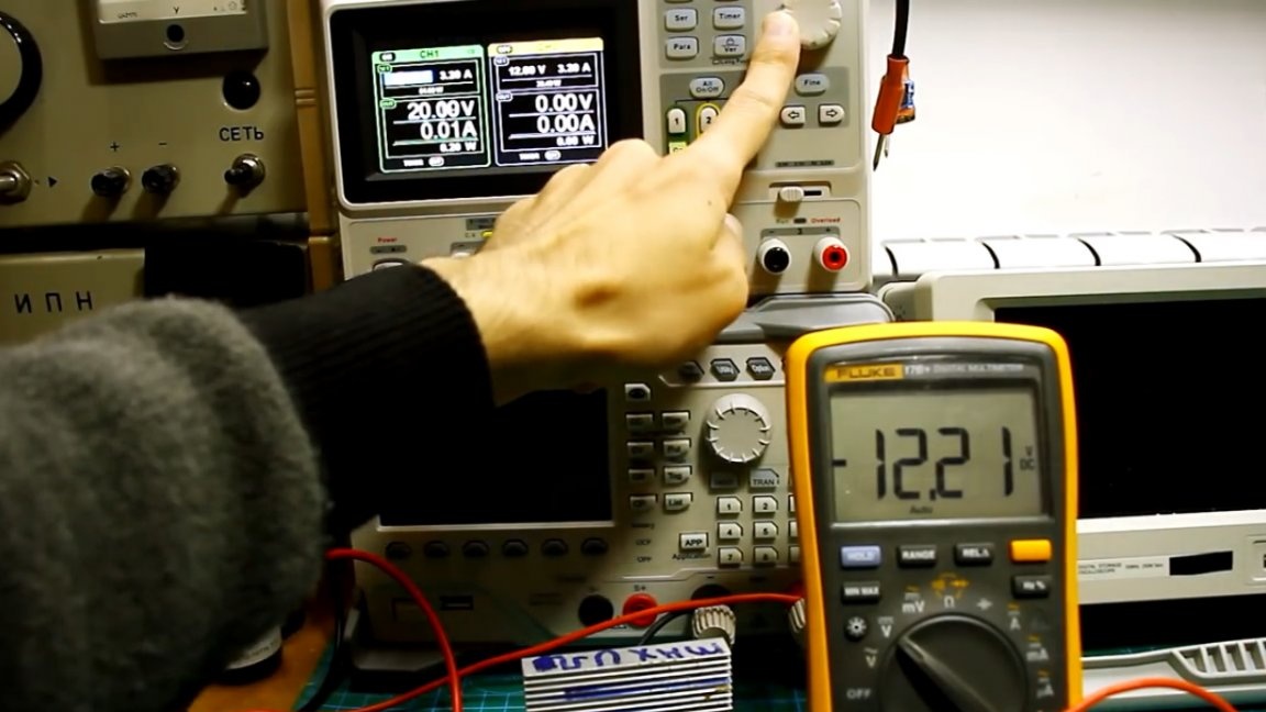
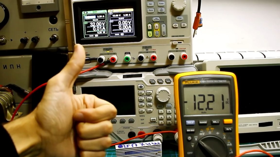
As you can see, everything is clear here, the set voltage is kept stable. Next, check the current stabilization, set the output current to 1A and repeat the same test.
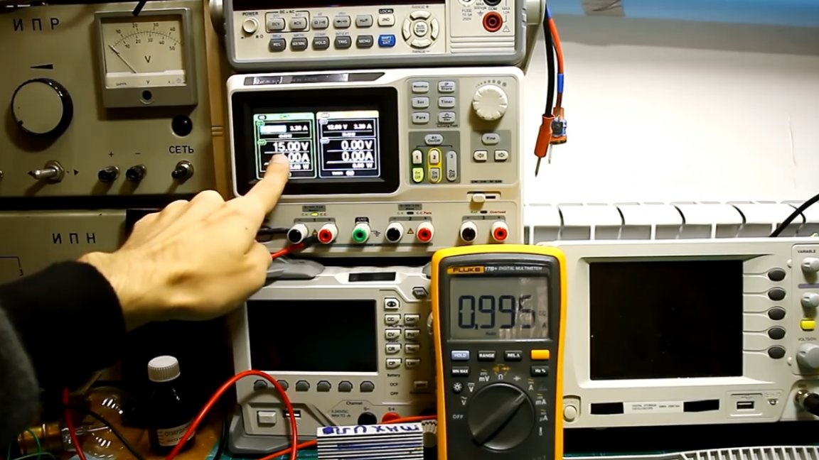
Here, too, everything is fine, the unit also behaves adequately, the output current does not change.
That's all. Thank you for attention. See you soon!
Author's video: