

In this article I will tell you how I made a simple device that allows you to check the health of quartz resonators and generate reference frequency signals in a wide range. And also determine the frequency of quartz resonators, if it is not known.
Repeat the device is not difficult. Enough basic knowledge, skills and a minimum of materials and tools.
At present, quartz resonators can be found at every step. They are used in watches, radios, televisions, computers, mobile phones, cars, and even in some washing machines and refrigerators!
Of course, master friends also use quartz in their designs.
Many years ago, I assembled a primitive instrument according to a scheme from a magazine. A quartz resonator was inserted into the socket and the exact, stable frequency indicated on the quartz case was obtained at the output. It helped to check and configure receivers and other devices.
Over time, a large selection of quartz appeared and, it would seem, now you can generate many reference frequencies. However, I began to notice that not every quartz works in this device. In addition, it became necessary to check the quartz resonators for proper operation before installing them in their designs and during the repair of various equipment. The device disappointed me and I sold it or just presented it to someone, I don’t remember exactly.
Recently, I decided to manufacture a similar device, using the accumulated knowledge and experience. According to my idea, the new device should be many times better, while maintaining simplicity in manufacture. That's what I did.
This is a circuit diagram of the device.
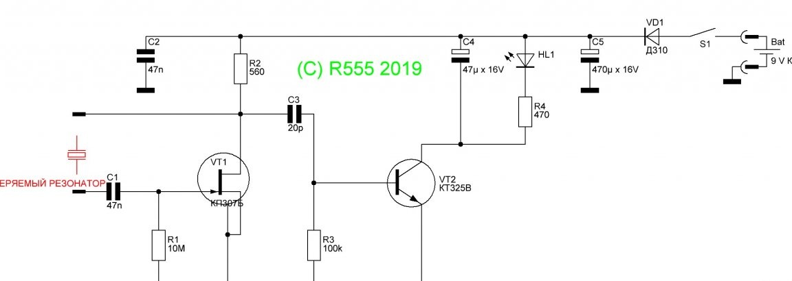
Conditionally, I broke it into two parts.
Generator. When a test quartz is connected, if it is working, generation occurs. The generation frequency is determined by a quartz resonator. It turns out a low-power transmitter, in the signal spectrum of which, in addition to the fundamental frequency, its harmonics are present, that is, frequencies that are multiples of the fundamental. For example, if you connect quartz to a frequency of 10 MHz, the spectrum will also include frequencies of 20 MHz, 30 MHz, and so on. This allows you to check and fine tune various equipment.
Indicator Detects the presence of generation and lights up the LED.
The generator parts are subject to very stringent requirements. Generation should occur when you connect any serviceable quartz, any design. At the same time, “spurious” generation should not occur, that is, in the absence of quartz or when a faulty resonator is connected.
I decided not to use a bipolar, as can be found in most such devices, but a field effect transistor. So the circuit is simpler and more stable in operation. The operation mode of the transistor VT1 DC is set by resistors R1 and R2. The quartz under test is connected through the capacitor C1 to the gate and drain of the transistor. With a healthy resonator, positive feedback is created and generation occurs. To connect the quartz, I decided to use small crocodile clips with short wires. These clamps make it easy to connect quartz with a variety of pins. The wires also serve as a transmitting antenna. Capacitor C2 short-circuits the power wire to a common wire. The transistor housing is connected to a common wire.
Indicator part.
To make it as simple as possible, I decided to use the so-called transistor detector. It used to be called a triode detector. It can occasionally be found in old radio sets. Unlike a diode detector, a triode detector not only detects, but also amplifies the detected signal. Oscillations from the output of the generator part through a capacitor of small capacity C3 go to the base of transistor VT2. With positive half-cycles of the oscillations, the transistor opens and current pulses flow in its collector circuit. These pulses charge the capacitor C4. Parallel to the capacitor through the limiting resistor R4 is connected LED HL1, which starts to glow. The base of the transistor through a resistor R3 is connected to a common wire, therefore, in the absence of a signal, the transistor is closed and the LED does not light. Thus, the indicator part unambiguously shows the presence or absence of generation, that is, the serviceability of the quartz resonator under test.
The power supply circuit of the device consists of a block for connecting a 9V Krona battery, a switch S1, a diode VD1 for protection against overtaking, and a capacitor C5.
Next I will tell you how to make this device.
Details and materials:
Transistor KP307B
Transistor KT325V
Diode D310
Small-sized ceramic capacitor 47 nF - 2 pcs.
Small-sized ceramic capacitor 20 pF
47μF x 16V Electrolytic Capacitor
Electrolytic Capacitor 470μF x 16V
10 MΩ resistor
Resistor MLT-0.125 560 Ohm
Resistor MLT-0.125 100 kOhm
Resistor MLT-0.125 470 Ohm
Light-emitting diode
Latch switch or button
Krona Battery Pad
Crocodile clip - 2pcs.
Plastic transparent container for small items
Fiberglass foil
Stranded wire
Solder
Rosin
Foam rubber
Glue
Solvent 646
Rags
Instruments:
Soldering Iron 25-40 W
Nippers
Scissors
Knife
Awl
Tweezers
Pliers
Jigsaw
File
Mini drill with nozzles
Permanent marker
Ruler
Magnifier
Sewing needle
Multimeter
Manufacturing process.
Step 1.
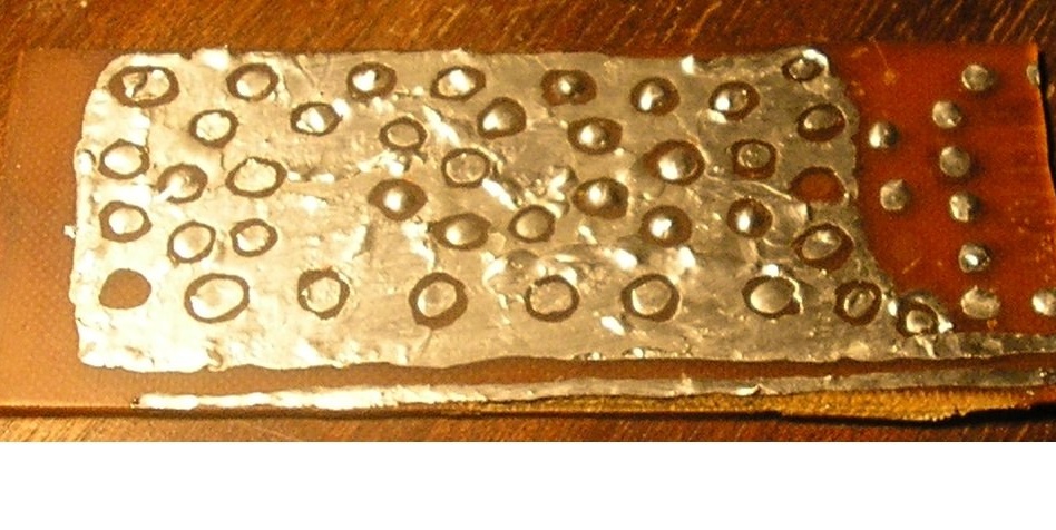
Board manufacture.
As a workpiece, I decided to use a home-made board made of foil fiberglass, which I made many years ago. It was collected layouts of several devices. It is good in that there are small circles of "patch" surrounded by foil that acts as a common wire. This board is ideal for the manufacture of RF devices, which is this device. Also on this board is a power cord in the form of a track. If you don’t have such a board, it’s easy to make it by cutting circles with a mini drill with a nozzle like a dental bur.Or using a ruler and a cutter made from a hacksaw blade. In this case, you need to cut out not the circles, but the squares.
Step 2
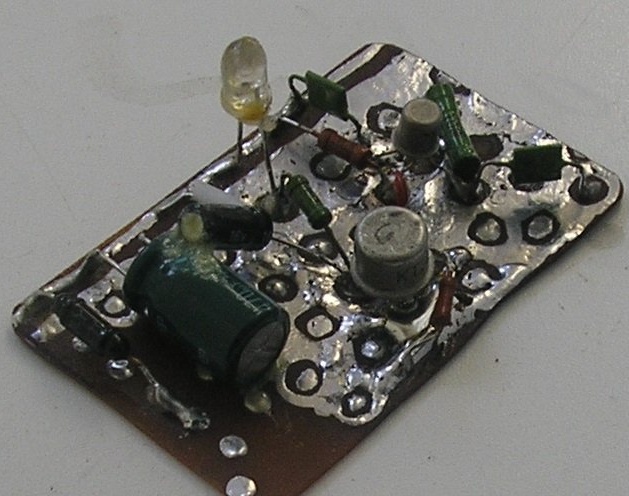
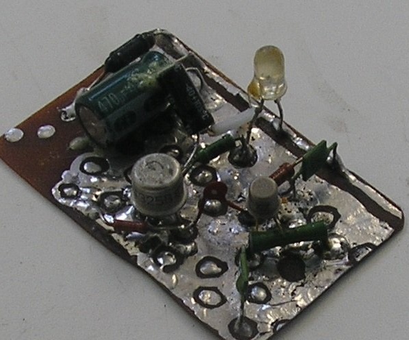
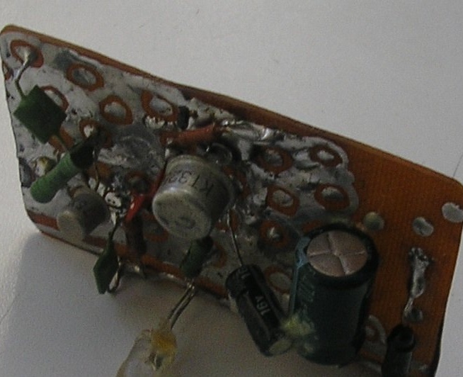
Mounting parts on the board.
Having stained the findings of the parts, I unsoldered them on the board, as shown in the photographs. During installation, I tried to make the conclusions of the parts as short as possible, this is important for RF devices. Then, using a jigsaw, he carefully sawed off unnecessary parts of the board on both sides and processed the edges with a file. Of course, this is wrong, these operations must be done before the installation of parts. But the thing is that I didn’t know exactly how many details and what would be needed for this homemade. Determined in the process. Using a magnifying glass, he examined the installation, paid special attention to the absence of short circuits of “piglets” with the surrounding foil. Using a sewing needle and a cloth moistened with solvent, I cleaned the board from the residue of rosin. As a result, I got a board measuring 65 x 40 mm.
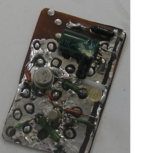
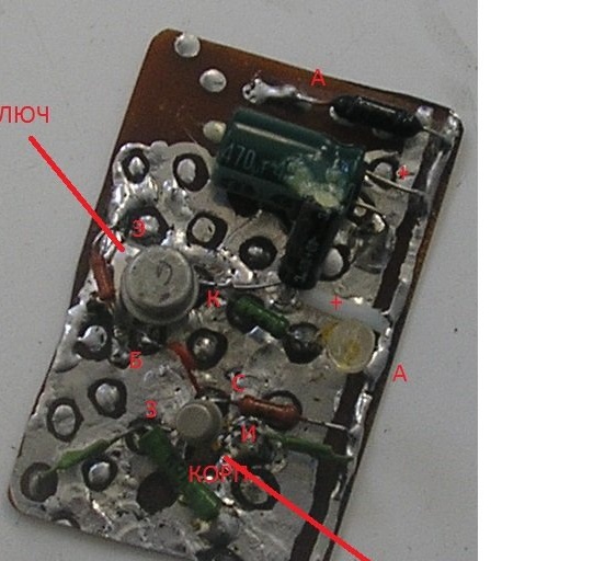
Here, the designation of the terminals of the transistors, in the position as they are soldered on the board. Also indicated are the anodes of the diode, LED and the positive terminals of the electrolytic capacitors.
Step 3
Case manufacture.
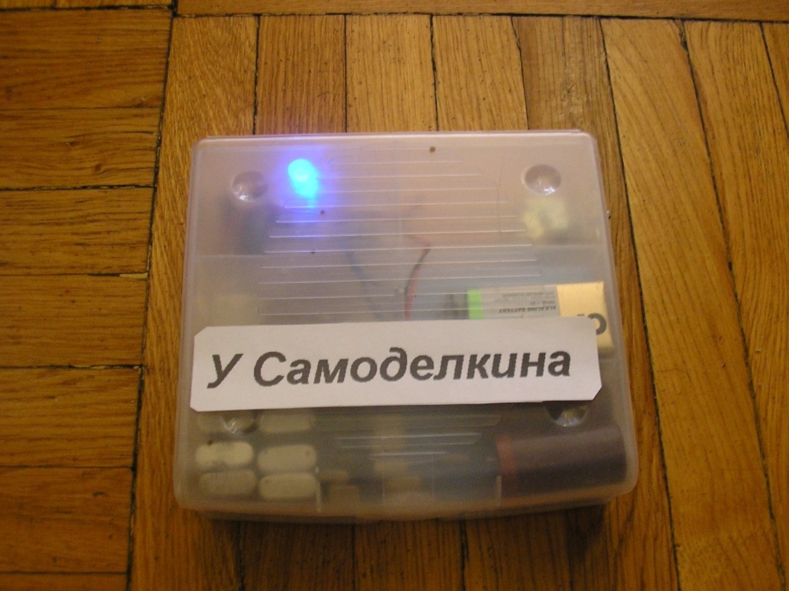
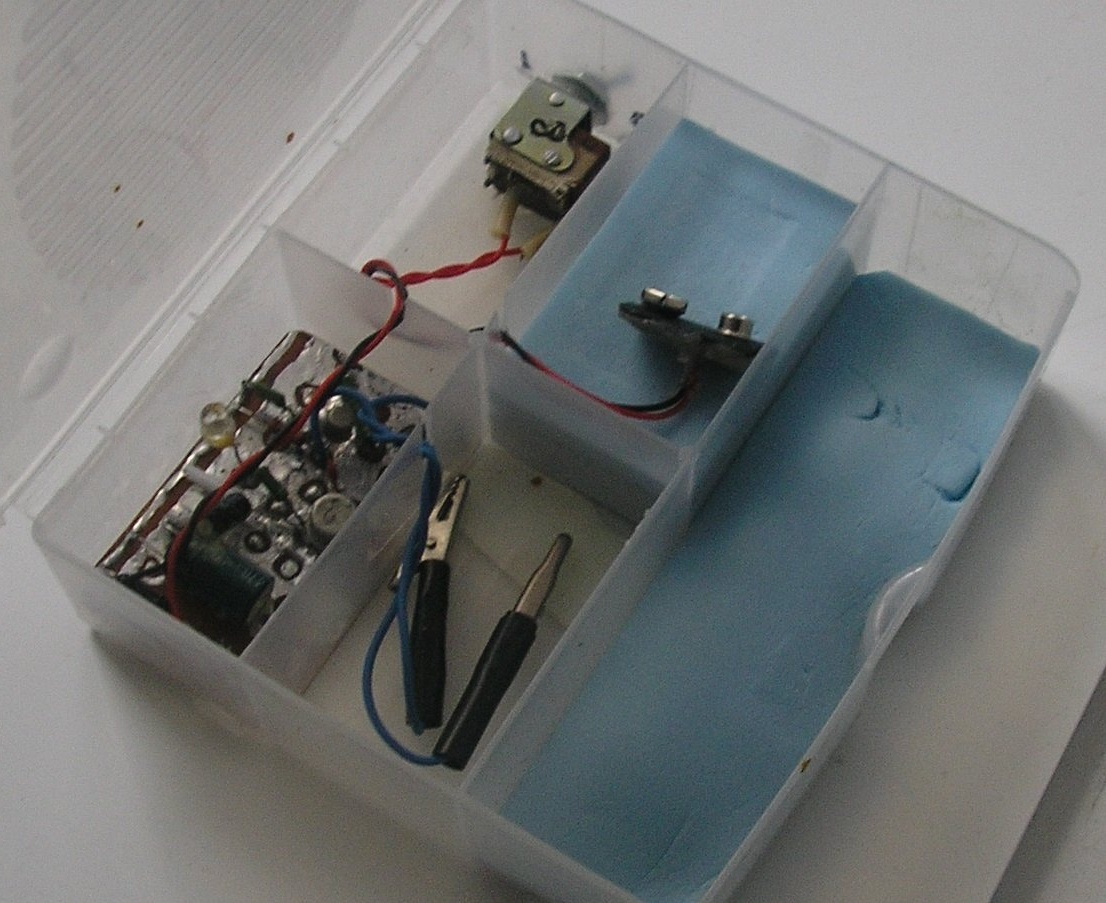
At first I wanted to make or pick up a finished metal case. But I came across a small plastic container for small things. Here it is.
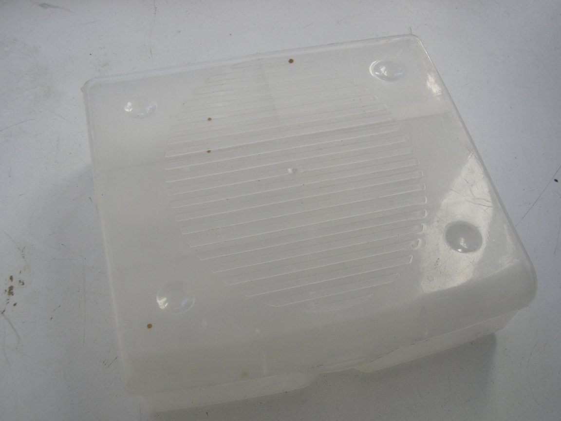

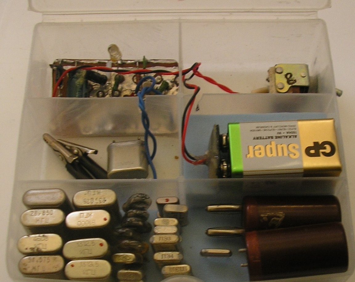
I decided to use it. It has 4 small and one large compartment. I figured that in one compartment it would be possible to place a board, in another battery, in the third power switch, in the fourth clamps with wires and connected quartz. In the fifth (large) compartment, you can place a set of resonators. In addition, the case is translucent, so you won’t have to think about where and how to place the LED so that it is visible from different angles. The case will freely pass the radio waves emitted by the device, while it will be possible to close the lid, no wires will dangle outside and it will be easy to move the device to the right place.
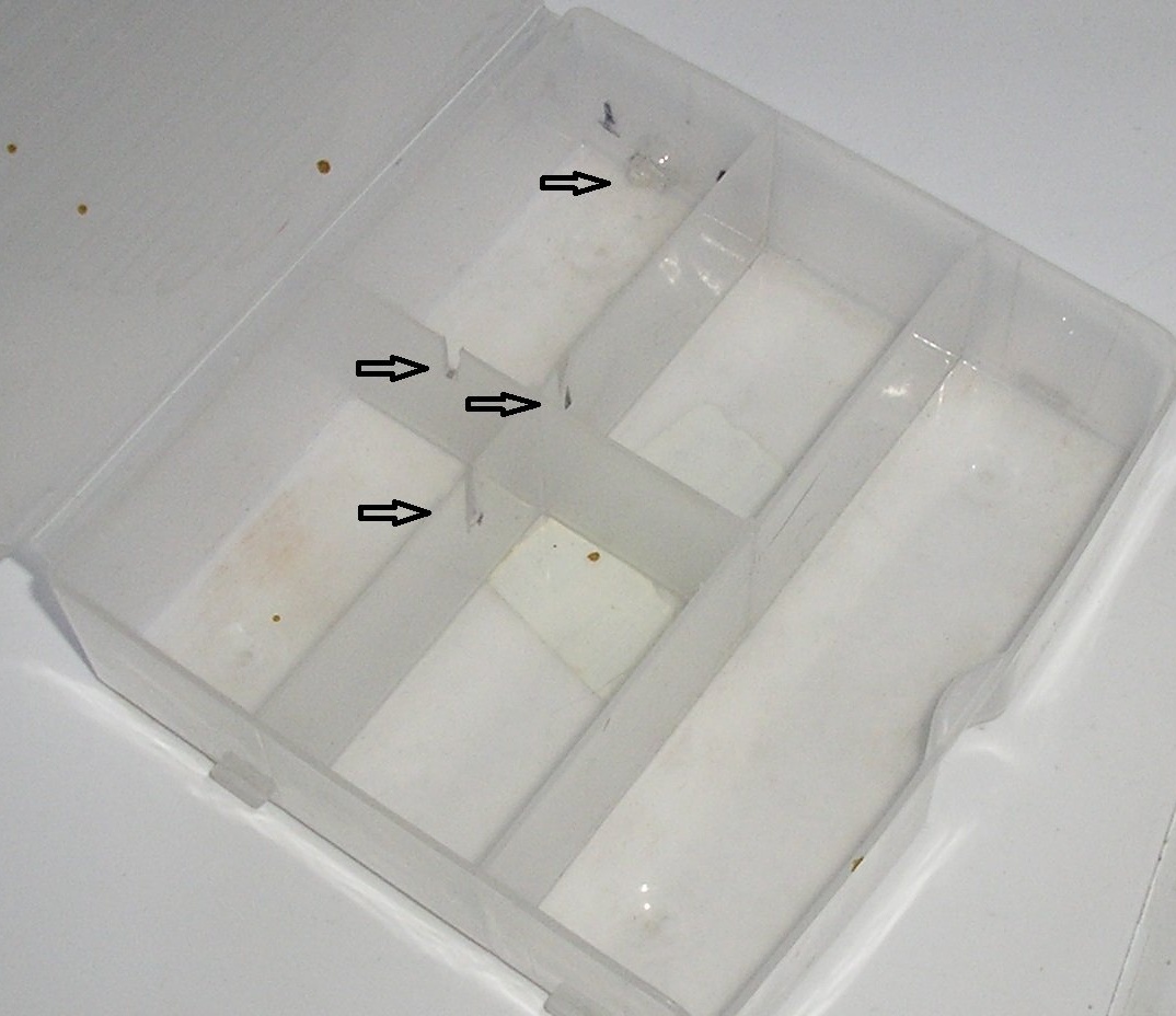
First of all, I marked with a marker the place of the hole for attaching the power switch and three places of slots for wires. Made a hole and slots.
Step 4
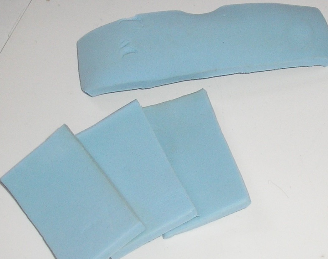
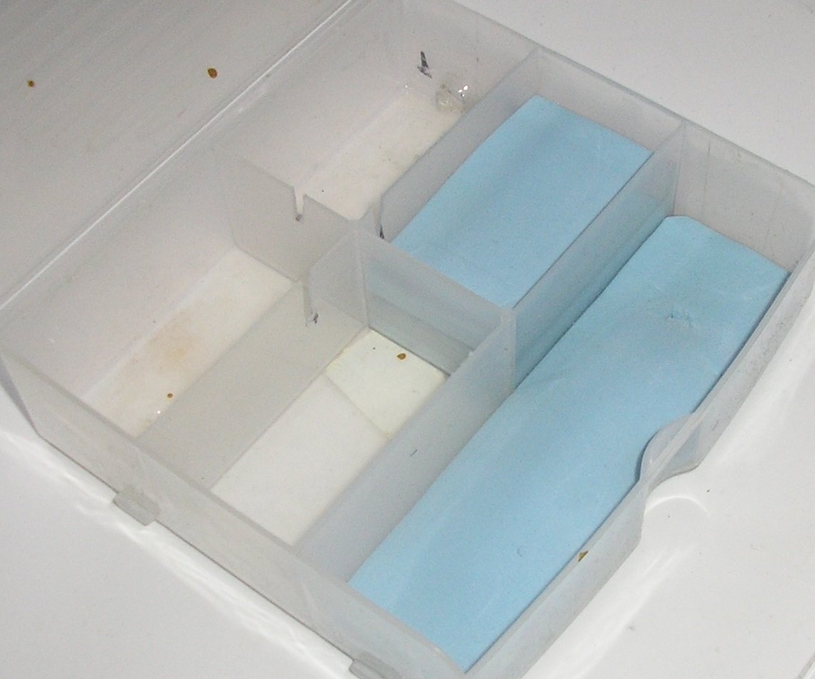
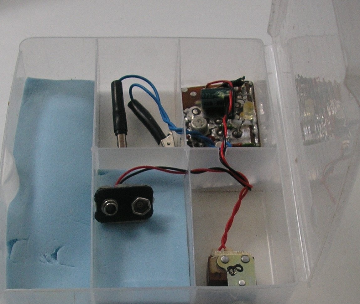
In order for the battery and a set of quartz to not hang out in the case, I cut 4 pads of foam.
And glued them to the appropriate places.
Step 5
Installation of the entire device.
I measured the required amount of wire to connect the board to the block and the switch, as well as the crocodile clips to the board. Wires took different colors. Soldered according to the scheme. Wires twisted among themselves.
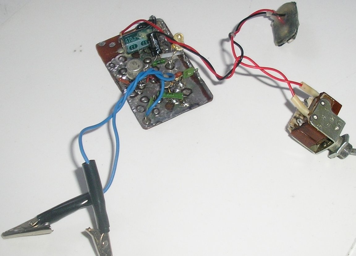
Step 6
Assembly in the housing.
He fixed the power switch with a nut, did not fix the board, it holds well in its compartment. I laid the wires in the corresponding slots. The device is ready!
Step 7
Checking the performance of the device.
Test results.
The device has been tested a large number of quartz resonators in the frequency range from 1,000 MHz to 79,000 MHz, a very different design. Different years of manufacture, starting in 1961. The device clearly identified faulty resonators. In addition, one serviceable quartz was deliberately disabled. To do this, a drop of glue was applied to the plate. The device showed that the resonator is faulty.
The signal emitted by the device (at a quartz frequency of 24,200 MHz) was recorded by a simple field indicator at a distance of 10 cm, and by a radio receiver (at the third harmonic) at a distance of at least 15 m.
The performance of the device was maintained when the voltage of the battery was reduced to 4.0 Volts (with a decrease in the brightness of the indicator).
The current consumption at a voltage of 9.0 V was 10-13 mA.
In the future I plan to improve this product.
1) Make an output for connecting a frequency meter.
2) Make switchable modulation a sound frequency signal (built-in generator).
There is enough free space in the case for this.
I am pleased with my homemade product and actively use it. Also gave for a while to a familiar radio amateur. Feedback is positive.
I hope this article will be useful to you.
I will be glad to your comments and suggestions.
Regards, R555.