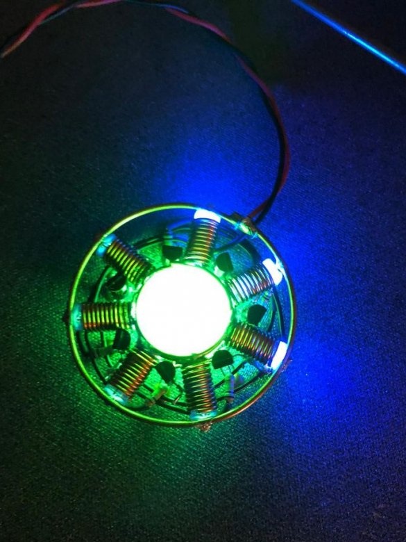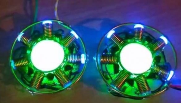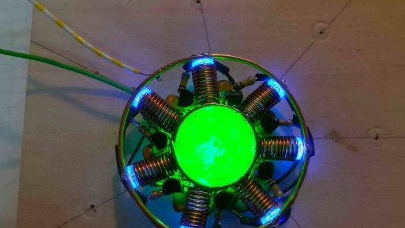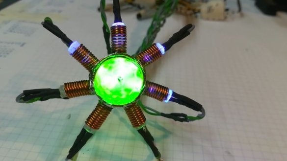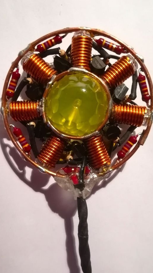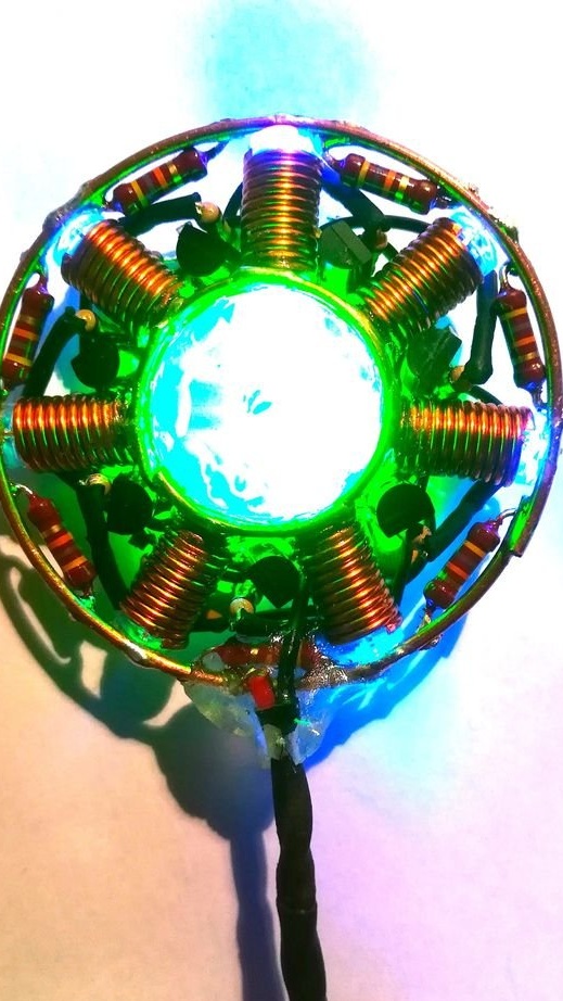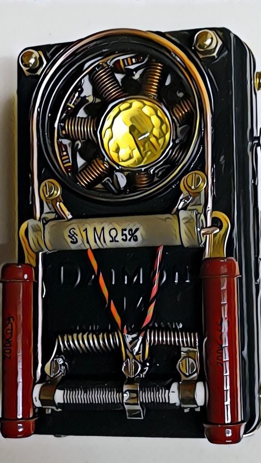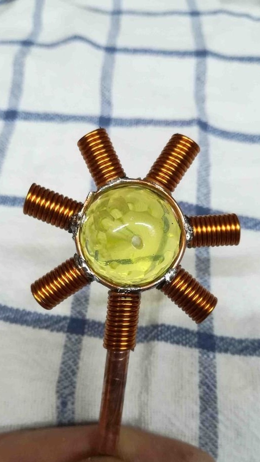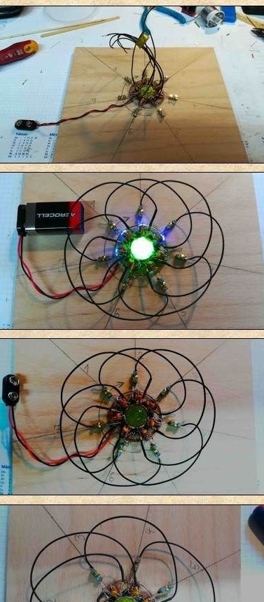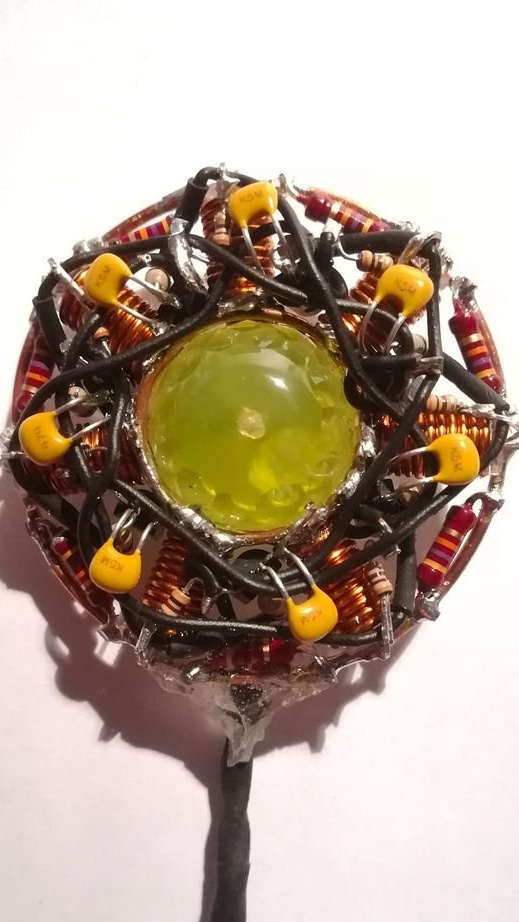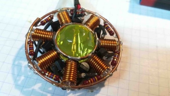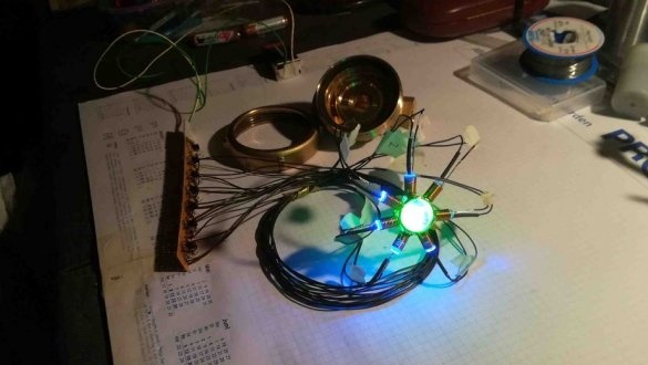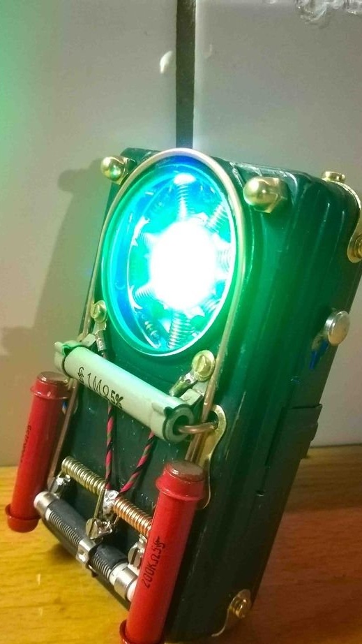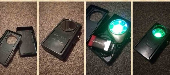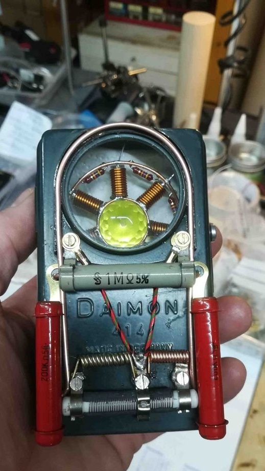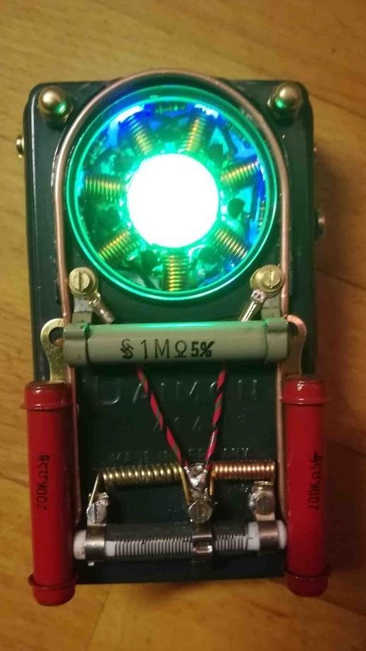
That is what the master called his work. Although, not even he, but a group of students from EDINBURGH HACKLAB who made this thing. The master, in turn, made a replica, and on its basis a little thing in style steampunk, and decided to share detailed manufacturing instructions with us.
Tools and materials:
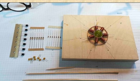
-Uranium glass ø 20 mm;
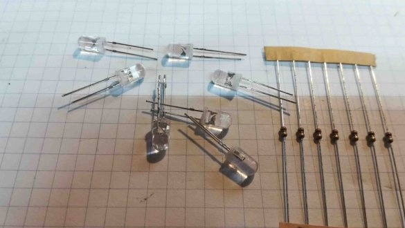
UV LED 5 mm 390-395 nm - 7 pcs;
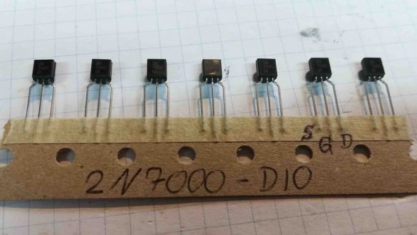
- Transistor 2N7000 DIO - 7 pcs;
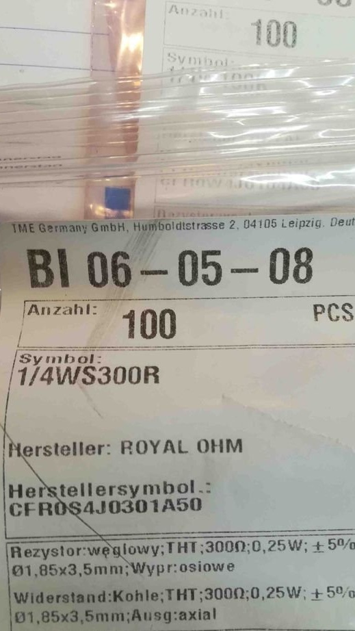
- Resistor 300 Ohm - 7 pcs;
- 0.47 uF ceramic capacitor - 7 pcs;
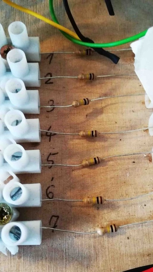
- Resistor 33K (for very fast rotation) or 100K (for very good rotation) or 200K (for very slow rotation) - 7 pcs;
- 9 volt battery;
-Battery clamp;
-Copper wire;
-Heat-shrink tubing;
-Pliers;
-Screwdriver;
-Soldering accessories;
-Nadfiles;
-Knife;
- "Third hand";
-Plywood;
-Engraver;
- Forstner drills 18 mm and 22 mm;
-Wooden toothpicks;
- Coin 20 eurocents;
-Small stick made of wood with a diameter of 5 mm;
Step one: basic concepts, scheme, theory
Uranium glass.
Uranium glass is glass in which uranium, usually in the form of diuranate oxide, is added to the glass mixture before melting. The fraction is usually about 2% by weight of uranium, and its radioactivity has very low alpha radiation. Uranium glass exhibits a very strong fluorescent effect when using ultraviolet light with a wavelength of 360 to 405 nm. The peak is about 395 nm.
(In Russia and the USSR, such glass was called "royal".)
Ring generator:
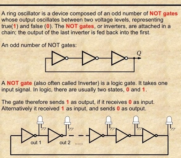
Wikipedia writes: “Ring generator - electronic "a device consisting of an odd number of inverting stages or digital inverters and serving to generate a sequence of rectangular pulses."
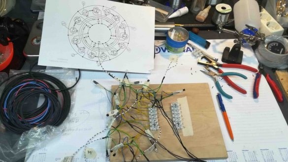
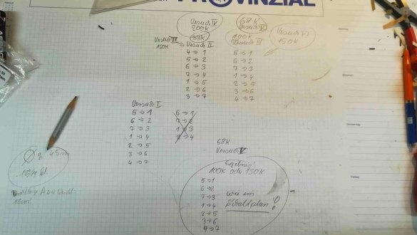
The members of Edinburgh Hacklab who made the UMRO (hereinafter referred to as the Oscillator) changed the sequence of these inverters in such a way that it seems that a ray of light rotates inside the glass marble. These inverters work very fast, so a capacitor and a resistor are needed to reduce the speed. Ceramic capacitors are a little more expensive than resistors, so the master decided to leave the 470 nF capacitor and changed the number of resistors to find the best speed. You can use different capacitors for different speeds: 33 kOhm - very fast rotation up to 200 kOhm - very slow rotation, 100 kOhm average.
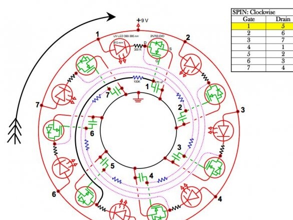
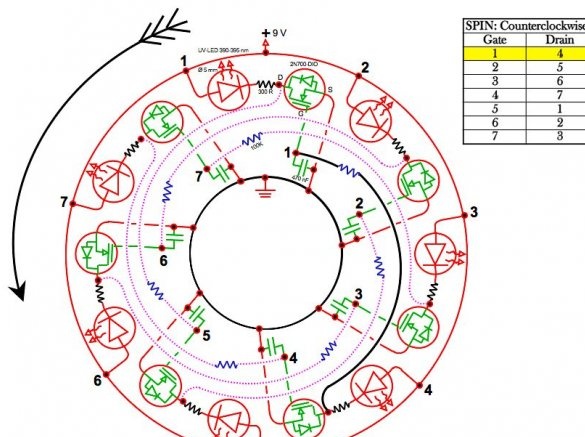
Rotation can be either clockwise or counterclockwise. How this is regulated will be described in the next steps.
This circuit is powered by a 9 V battery, but the master also tested 3 AA batteries of 4.5 V. Everything works with this voltage. True, the rotation speed was slightly lower, and the light from the UV LED was weaker. This made it clear that if you install a potentiometer, you can adjust the speed of rotation.
Step Two: Prepare Copper Coils and Rings
The master planned to build several oscillators, so in the description there is an instruction for assembling one UMRO, and there are more details in the photos.
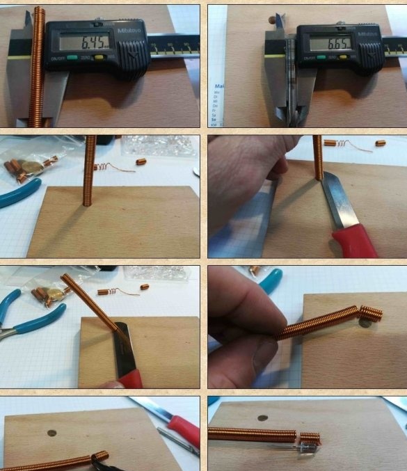
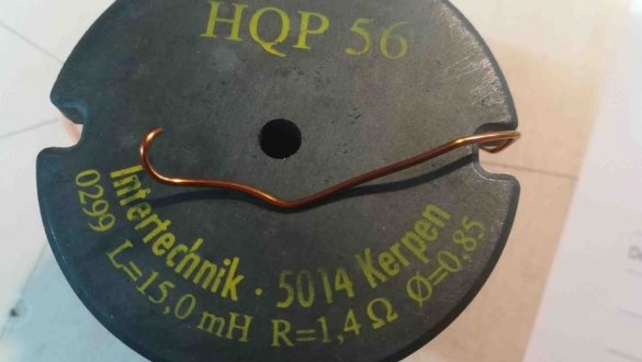
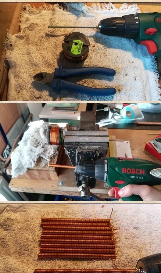
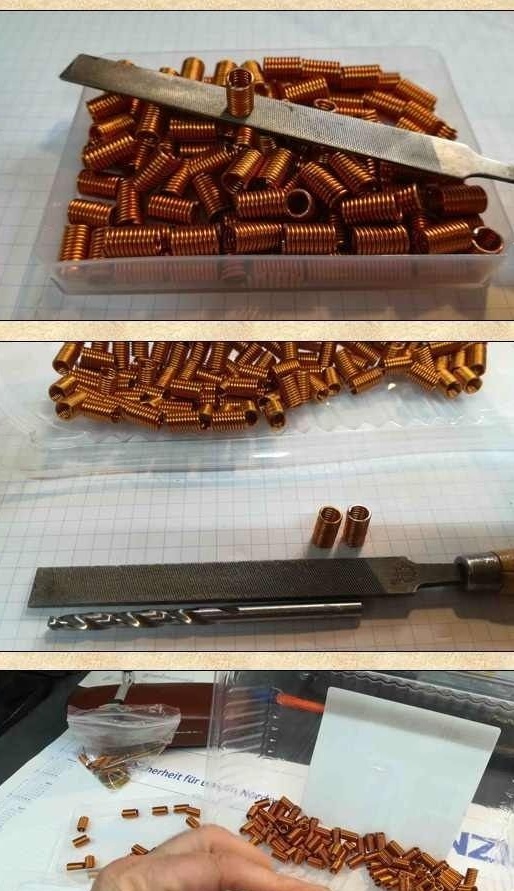
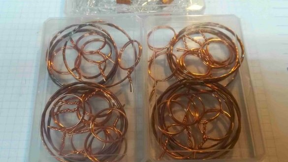
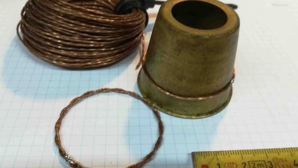
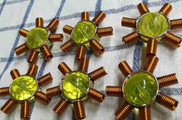
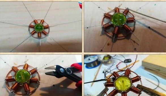
On a stick with a diameter of 5 mm (LED diameter), the master winds a copper wire with a diameter of 0.85 mm. The length of the coil is 10 cm. Then the coil is cut one centimeter. One oscillator needs seven coils.
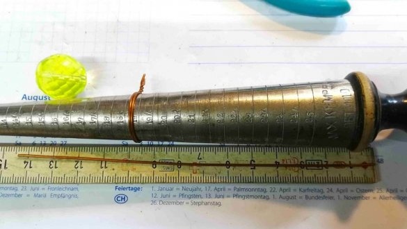
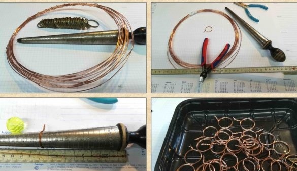
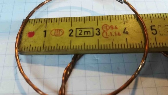
Now you need to make three rings. Two rings will serve as a frame for glass, their diameter is 19 mm, and one ring will be located on the outer perimeter around the coils, its diameter is 45 mm. These rings can be made in any way, fly, twist, weave patterns, etc.
Step Three: Install Coils
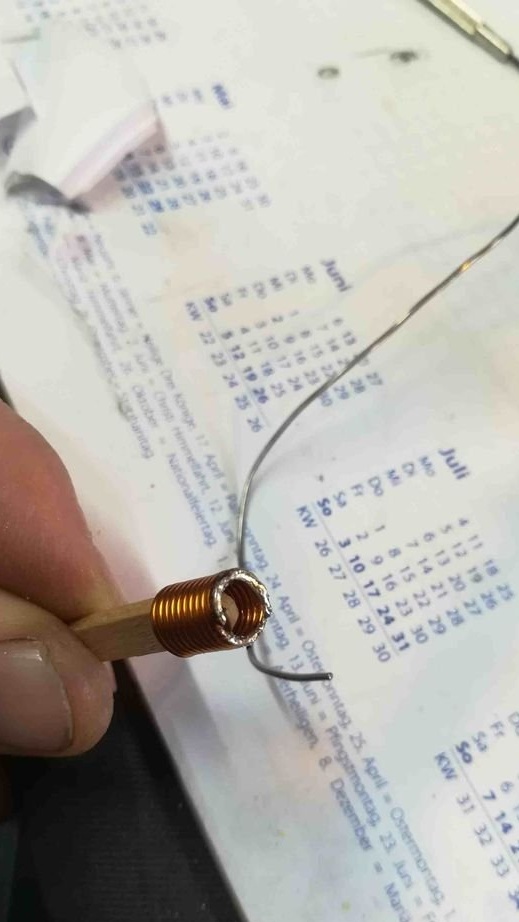
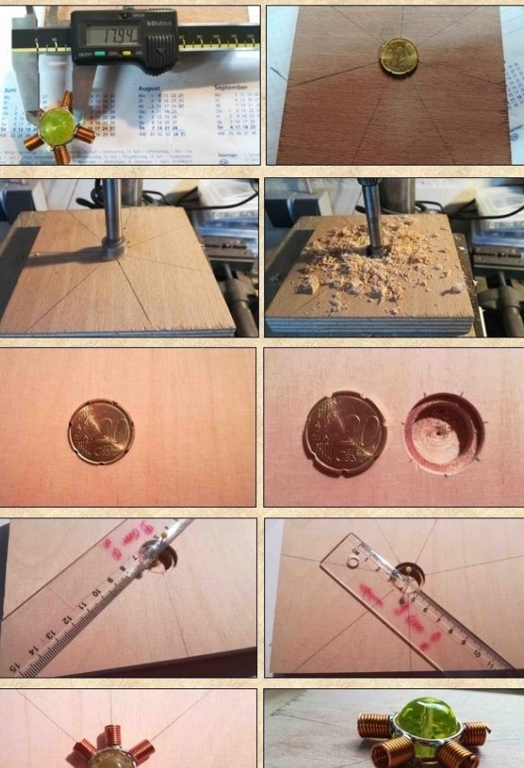
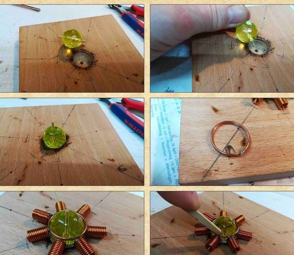
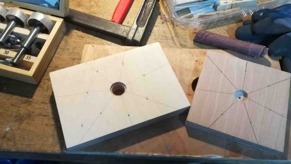
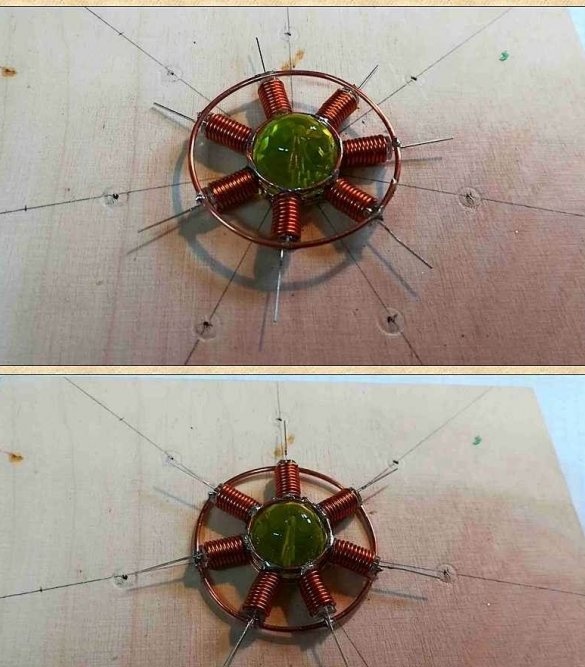
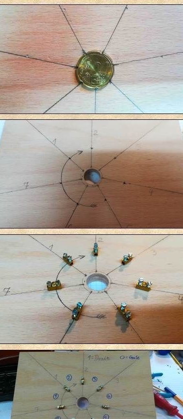
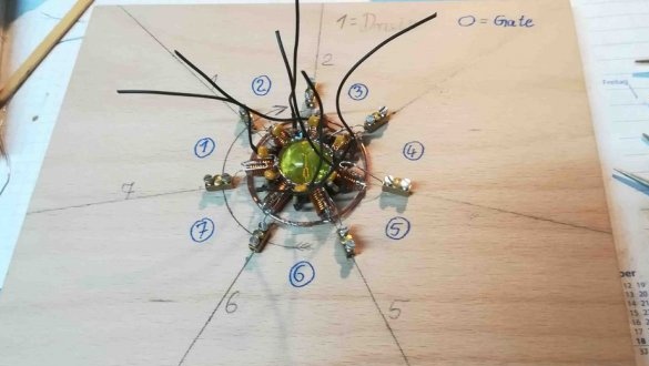
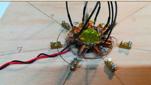
To set the glass and attach seven small coils, the master makes a template from plywood. Drill a blind hole ø 22 mm in plywood, then a blind hole 18 mm and a through 2 mm. There is a hole in the glass. Inserts a toothpick into the hole and centers it in the 2 mm hole in the plywood. Then it places a copper ring on the glass and solders seven coils around the circumference. Turns the glass and solders the second ring.
Step Four: LEDs
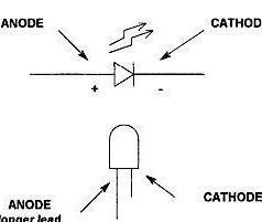
Next, check each UV LED before use. Testing can be done using a 9-volt battery and a 300 ohm resistor. If everything is normal, then a UV LED is installed in each coil. The anodes of the LEDs are soldered to the outer copper ring.
Step Five: Transistor Resistor, Capacitor
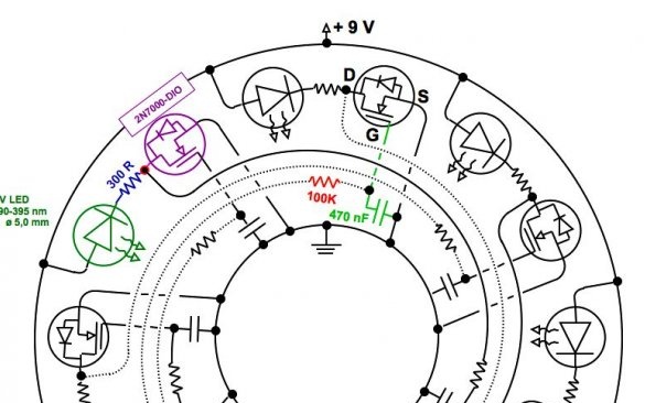
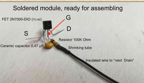
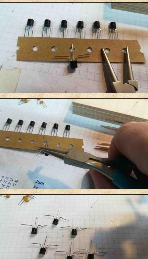
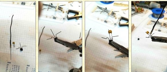
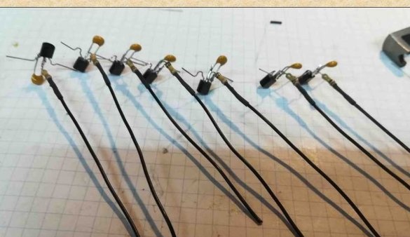
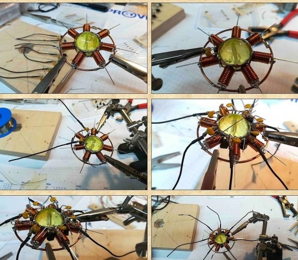
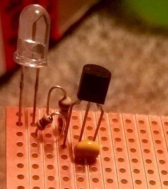
Next, you need a transistor 2N7000-DIO and bend the left and right legs, as shown in the photo. Now you need to solder the ceramic capacitor to the source and gate of the transistor. Solder a 100 kΩ resistor to the gate, isolate the thermotube connection. 5 cm of wire are soldered to another leg. So you need to prepare seven modules.
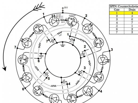
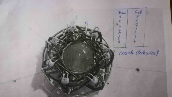
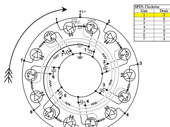
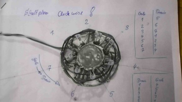
Now you need to solder the module leads to the inner ring (see photo and diagram)
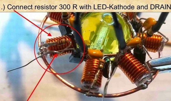
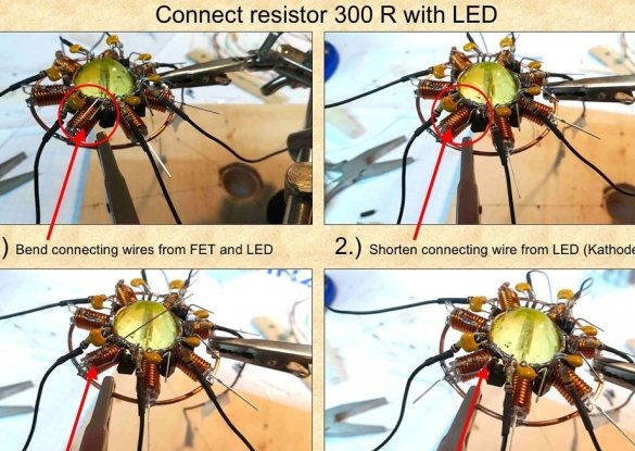
Finally, solder a 300 Ohm resistor to the cathode of the LED, and the other end to the drain of the transistor.
Sixth step: direction of rotation
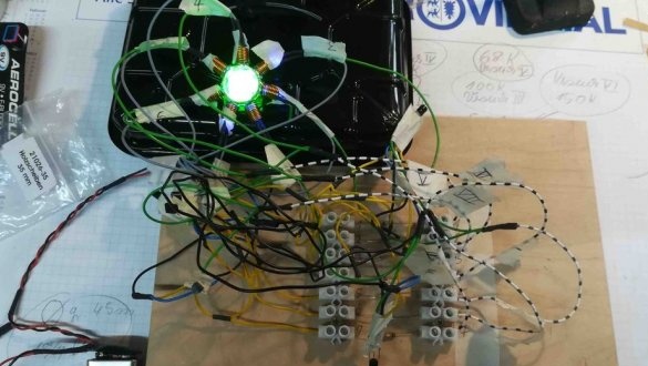
Now you need to continue the installation according to the schemes. The scheme is selected depending on which direction the "rotation" should be. The wizard provided both schemes. Before final assembly, it is best to verify that the circuit is working.
Seventh step: board
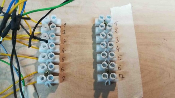
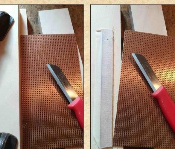
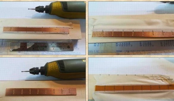
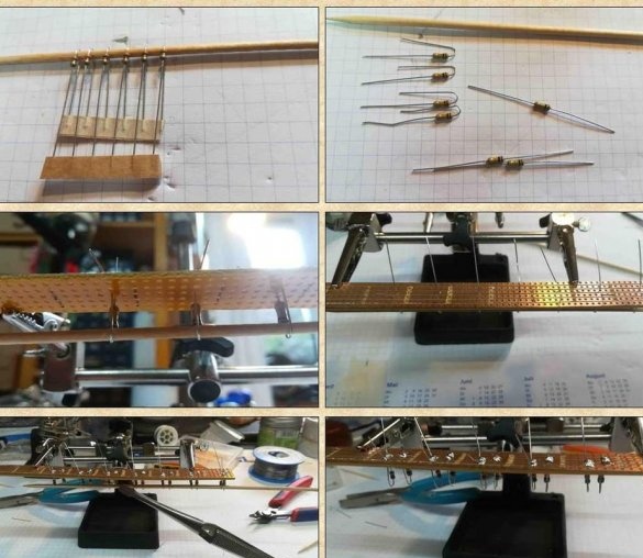
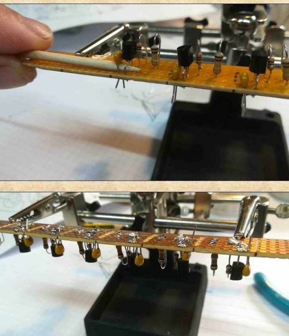
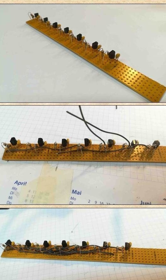
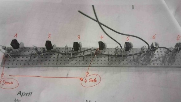
If necessary, you can assemble the circuit on the board.
Step Eight: Case
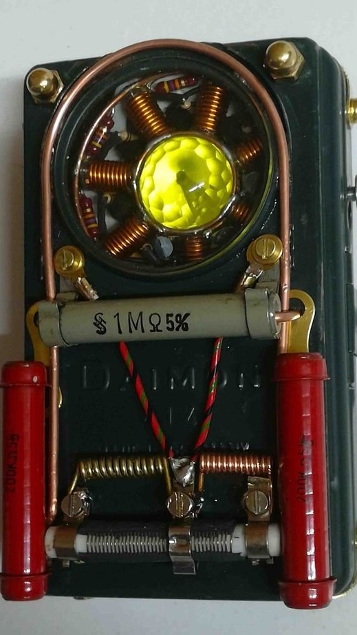
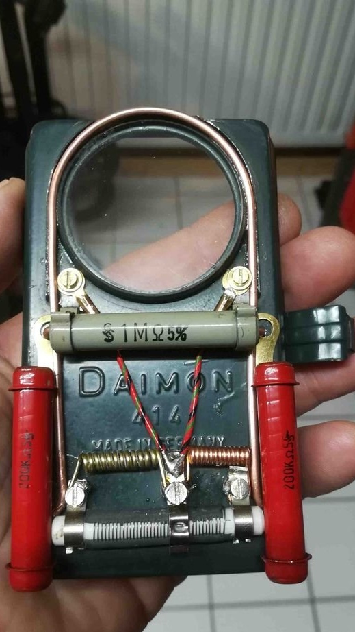
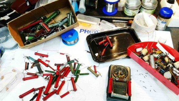
With the final step, the master places the oscillator in a metal case from the old police flashlight. For decor adds electrical components.

