What is necessary:
1. Energy-saving lamp for the housing.
2. LEDs 5630-0.5.
3. Chemistry for the manufacture of printed circuit boards.
4. Grandma's iron.
5. Electronic components for the driver.
6. Soldering iron.
There was a small bulb ø34 mm. If you put in it three LEDs 5630-0.5, working at half the power, then the problem will be solved.
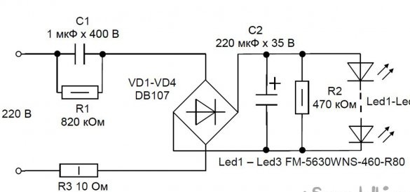
The driver had to be developed by himself, since there are none. It was decided to make a driver with a quenching capacity.
The output current of such a driver is 72 mA. Resistance R1 discharges capacitor C1. Resistance R2 - for a smoother start, R3 - eliminates inrush currents when turned on and is a fuse.
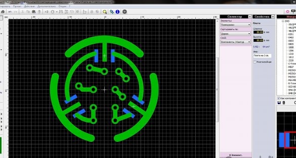
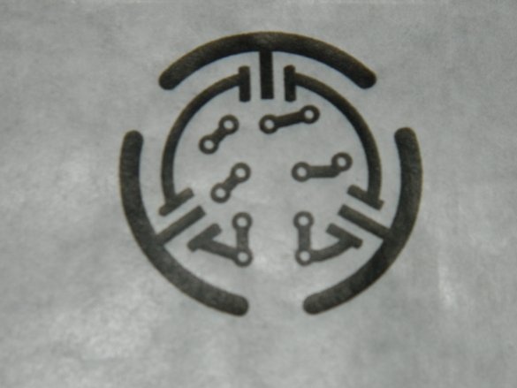
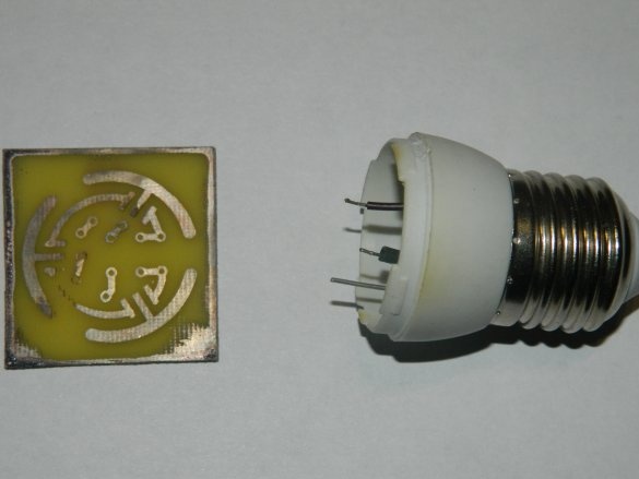
Sprint-Layout designed a circuit board sketch. Cooling of the LEDs is ensured by large arcs along the perimeter of the board, since the board on which the circuit should be assembled is made of fiberglass.
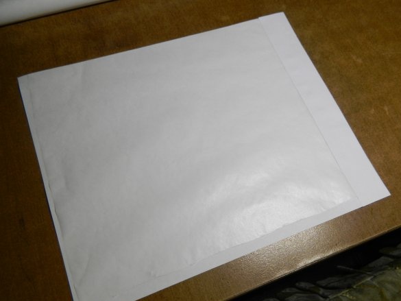
To print the picture of the board, I glued the envelope where I put the tracing paper, because the tracing paper in the inkjet printer is jammed. Printed with maximum contrast. In order to further increase the contrast, he processed the picture with an industrial hairdryer.
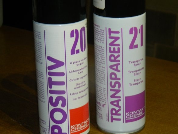
Cut a square board (with a margin). Sif treated with a thin sandpaper and detergent and applied Positiv 20 (photosensitive layer). To save time, kept in the oven at a temperature of 100 degrees 40 minutes. (So the board dries in a dark place for about a day). Then he sprayed the tracing paper with the Transparent 21 drawing, which makes it possible to make not only tracing paper but also paper transparent (it’s very convenient to print from magazines), and put it in the light setting.
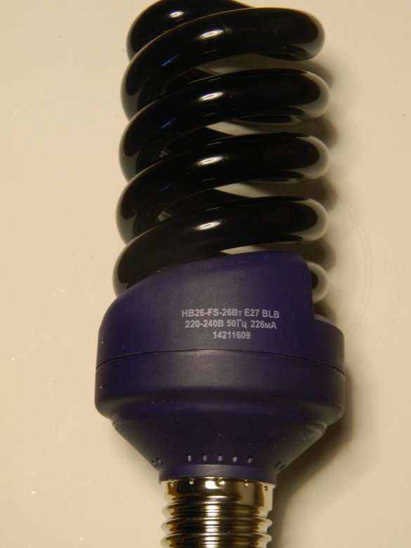
Illumination passed 40 minutes under an ultraviolet lamp from a distance of 25 cm.
Then he washed off the photosensitive layer with a 7% solution of caustic soda and etched it in a solution of ferric chloride for half an hour.
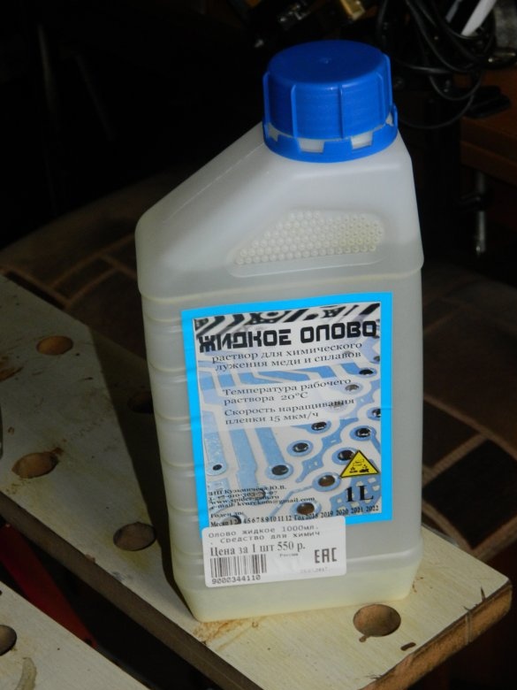
After washing with water, the board had to be adjusted to the diameter of the lamp, which was done with scissors and a file. Then the board was placed in "liquid tin" (a wonderful thing, albeit expensive) for 1 hour. As a result, the tracks were covered with tin.
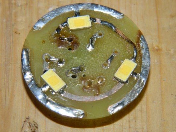
Using an iron, LEDs for screen printing were soldered onto the board.
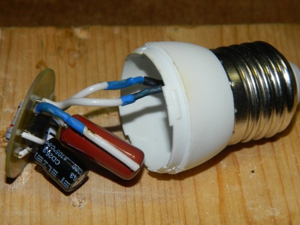
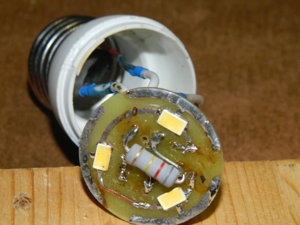
Next, the radio components were soldered onto the board, which were safely located in the lamp base.Only R3, which was soldered on top (between the LEDs), did not fit.
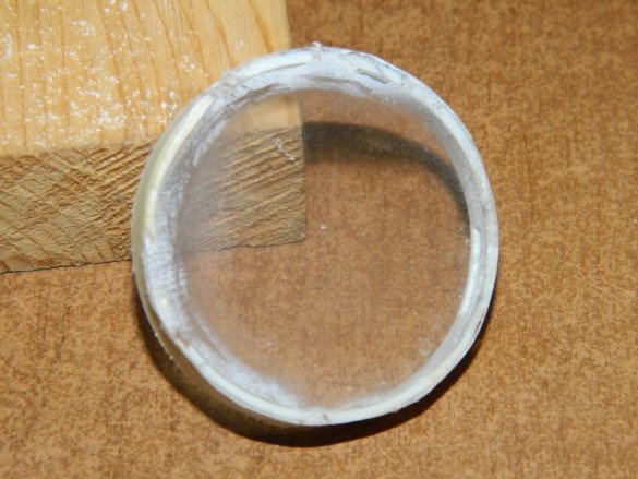
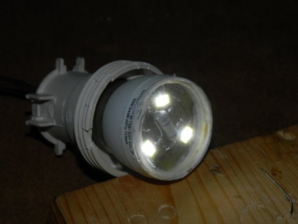
Since the driver does not have galvanic isolation from the network, there is a high voltage on the board. To protect myself (and others), I cut a transparent circle out of some kind of packaging (in my opinion, from headphones), cut off the flush of the lamp cover with a drill and pasted it with super glue.
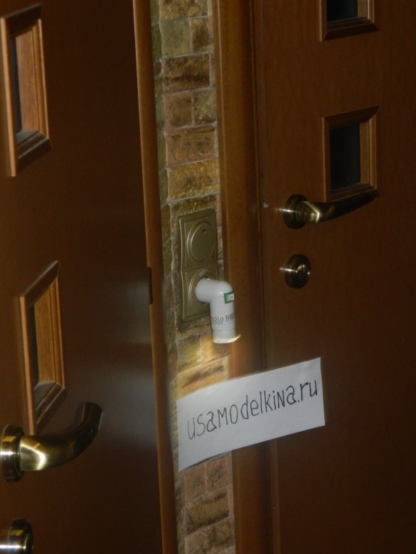
It turned out to be a good nightlight, which can work for whole days. According to calculations, its power is about 0.6 watts. It consumes electricity for a penny, and shines so that it can illuminate, for example, an entrance hall or doors to a toilet or bathroom.


