
Recently on sale a lot electronic designers of various firms. These are designers for assembling a certain device, and for those who want to try their hand at working with Arduino, and general designers for assembling various circuits. The prices of such products are basically several thousand rubles. But why not make such a designer yourself, and even involve a child in this work?
The electronic designer, the manufacture of which we will consider in this article, costs a penny, according to the master, one socket costs about 10 cents.
By the way, with the help of such a constructor, you can check the performance of many circuits. The assembly takes little time, there are no wires sticking out, like on a breadboard, and copper contacts are pressed tightly against each other with the help of neodymium magnets.
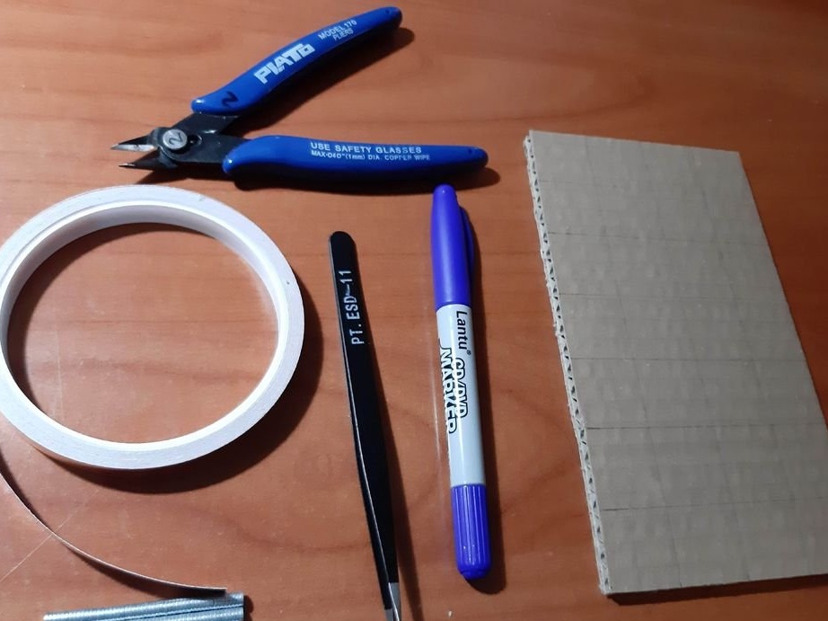
Tools and materials:
-Neodymium magnets;
-Copper tape with an adhesive layer;
-Three-layer cardboard;
-Battery holder;
-LEDs;
-Resistors;
-Capacitors;
-Transistors;
- Light-dependent resistor;
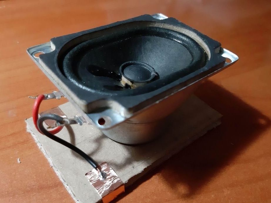
-Speaker;
-Buttons;
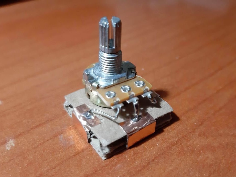
-Potentiometer;
--Scissors;
-Soldering accessories;
-Red and blue markers;
-Tweezers;
Electronic components can be supplemented according to needs.
Step One: Minimum Set
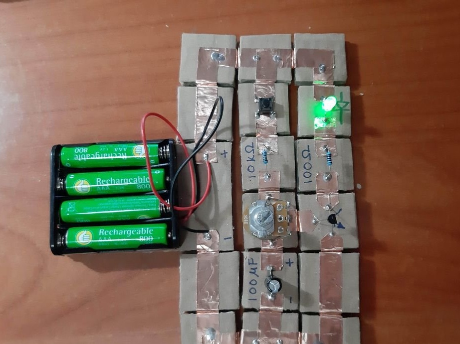
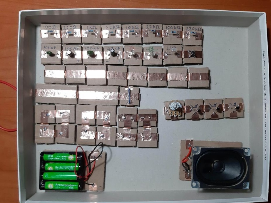
The minimum set of electronic designer are the following details:
4 straight connectors
4 corners
2 T-joints
1 battery pack
2 LEDs (green and red)
4 resistors (100 Ohm, 220 Ohm, 10 kOhm, 22 kOhm)
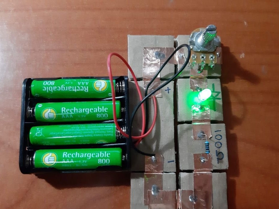
1 potentiometer (10 kOhm)
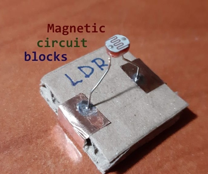
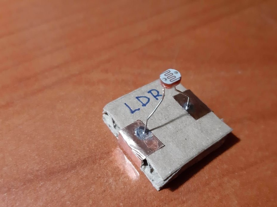
1 LDR (Light Dependent Resistor)
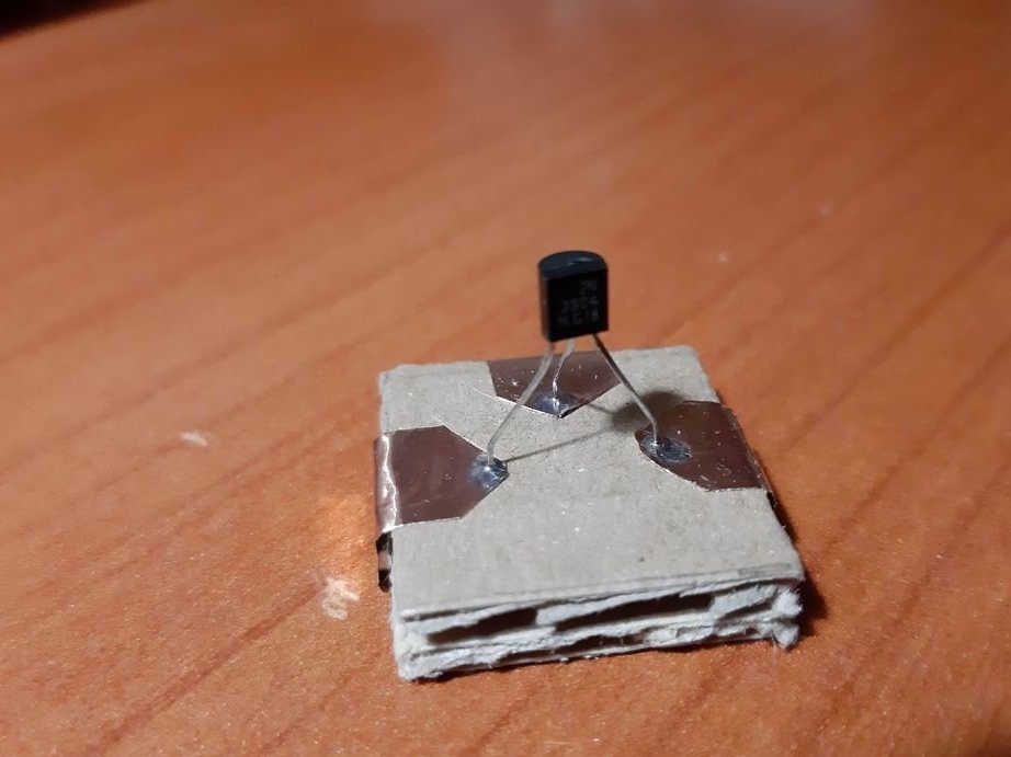
1 NPN transistor (e.g. 2n3904)
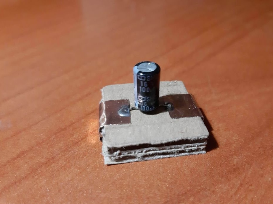
1 electrolytic capacitor 100 uF
1 button
1 touch pad
The minimum set consists of 23 blocks and it needs 100 neodymium magnets.
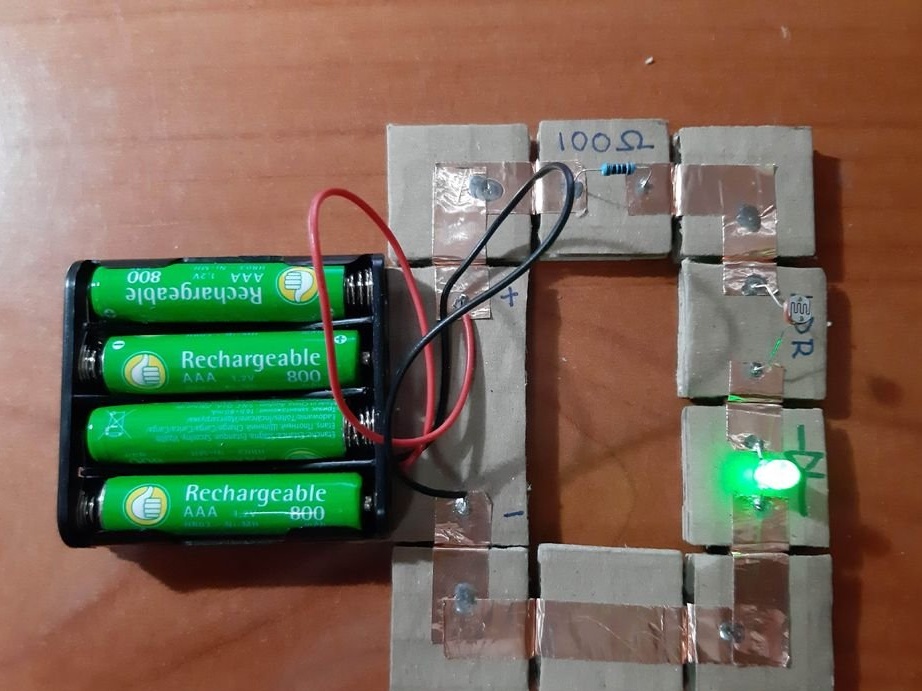
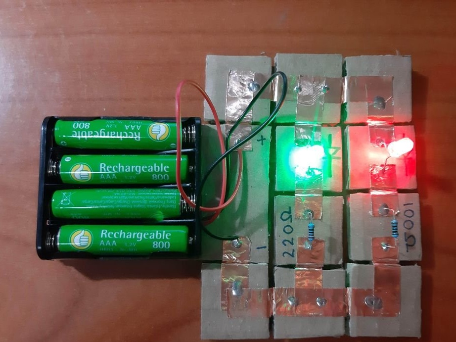
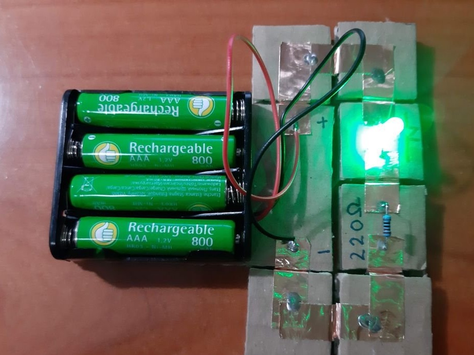
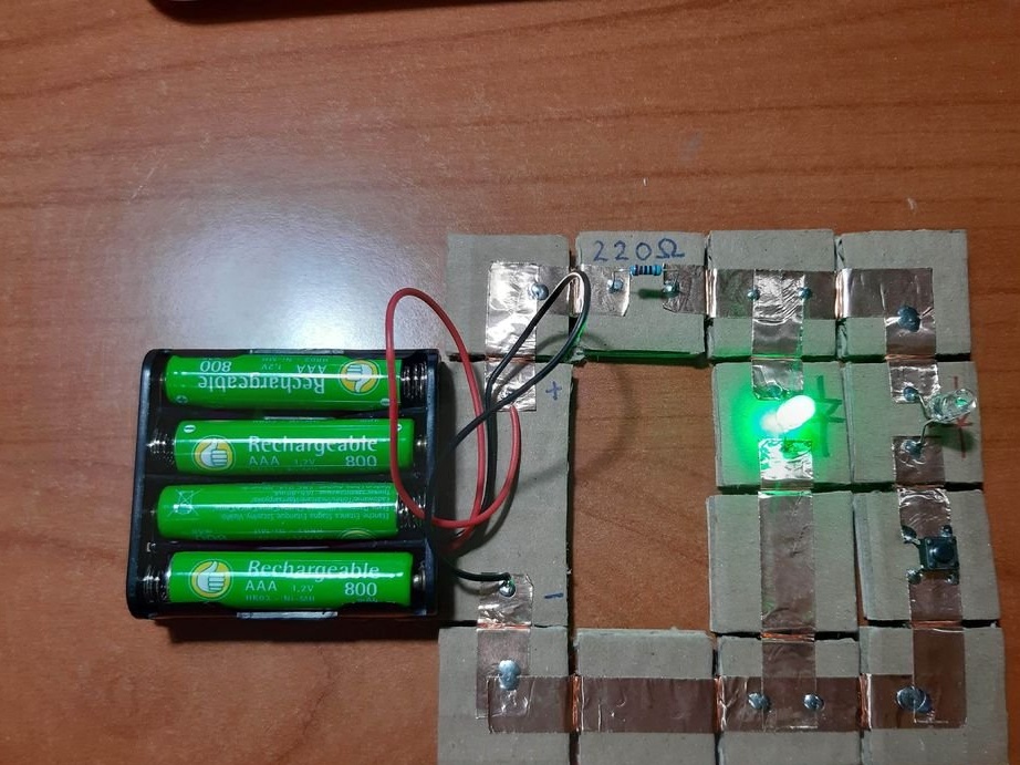
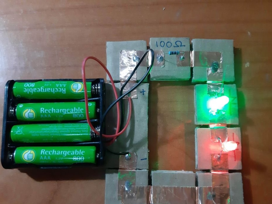
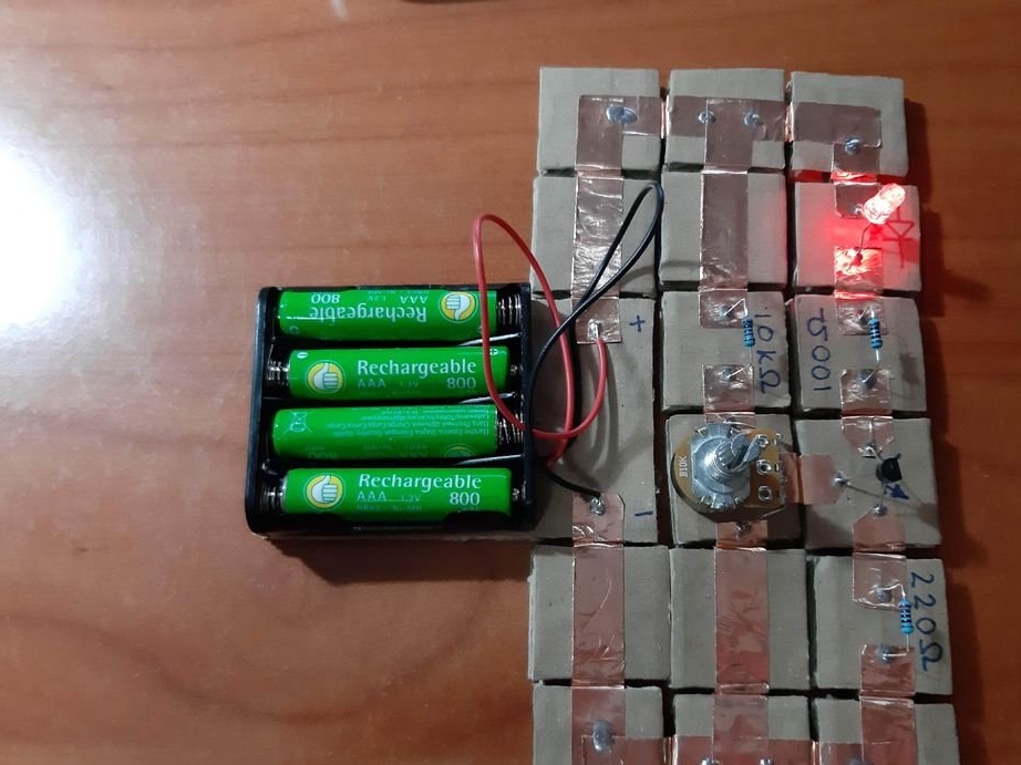
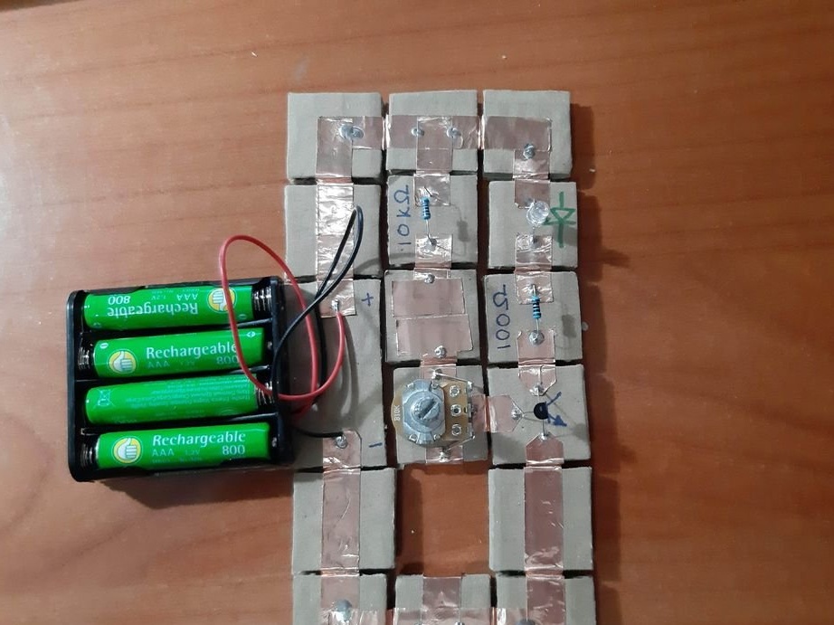
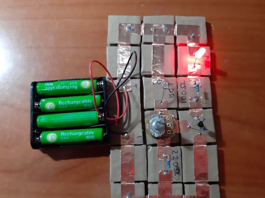
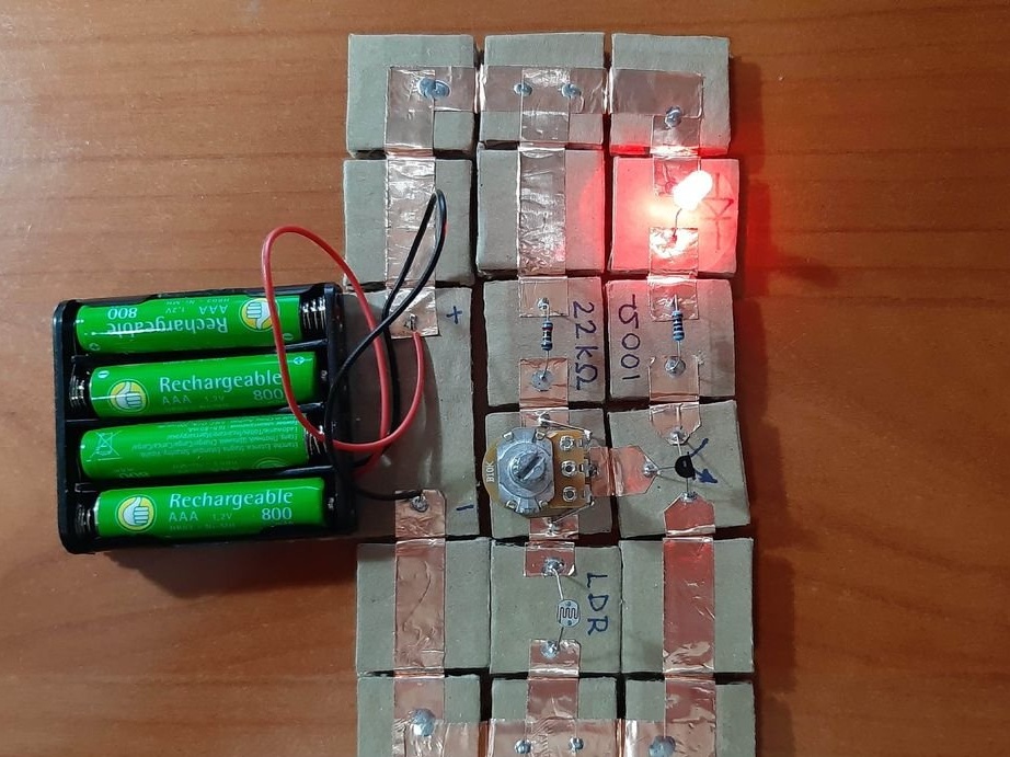
Below are 11 circuits assembled using this kit.
Step Two: Magnet Poles
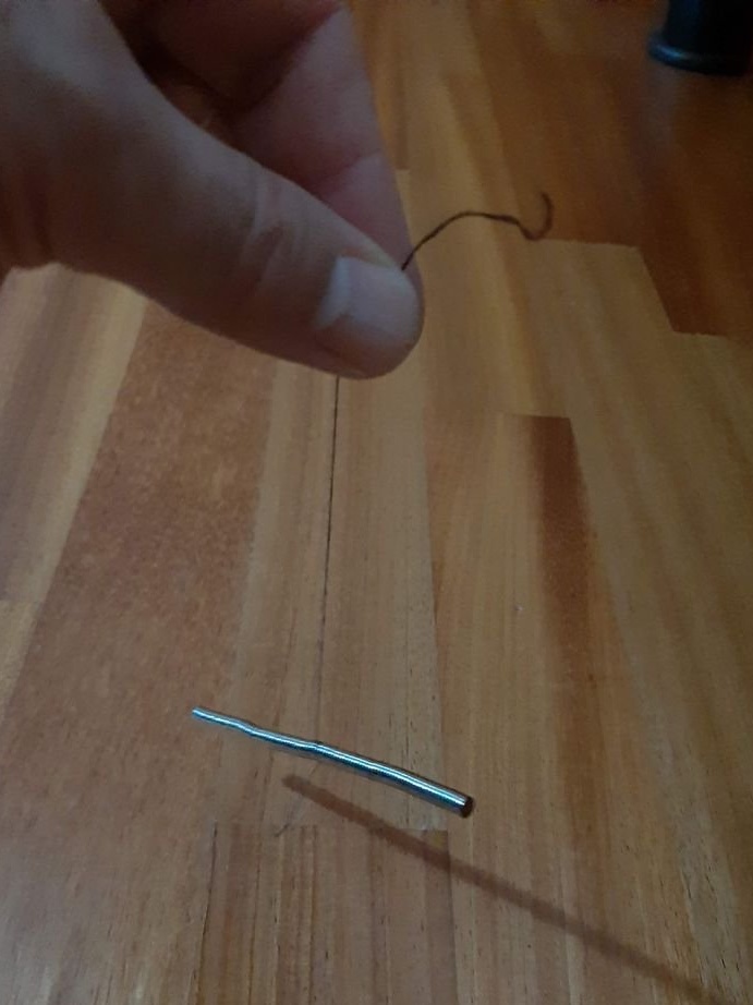
As we know from physics lessons, magnets have two poles, and are attracted to each other, by different poles. Neodymium magnets do not have pole markings, and the master labels them himself.To do this, he collects magnets in one strip and hangs on a thread. The side pointing north will be marked with a red marker and the one pointing south with a blue marker.
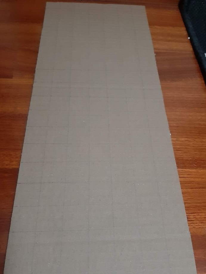
Step Three: Blocks
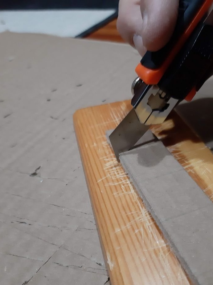
A sheet of cardboard needs to be drawn into squares 2.5 X 2.5 centimeters, several rectangles 2.5 cm X 5.2 cm and 5.2 cm X 6.4 cm. Then you need to cut according to the markup.
Step Four: Magnets and Copper Tape
Now you need to cut the tape in size.
Block of connectors: 4 magnets, ribbon 5 cm. Long block of connectors: 4 magnets, ribbon 8 cm. Corner block: 4 magnets, 2 pieces of ribbon 3 cm each. T-shaped connection: 6 magnets, 1 piece of ribbon 3 cm, 1 piece 5 cm tape. Cross connection: 8 magnets, 2 pieces of tape 1.5 cm, 1 piece of tape 5 cm, 2-pin component: 4 magnets, 2 pieces of tape 2 cm, 3-pin component: 6 magnets, 3 pieces of tape 2 cm.
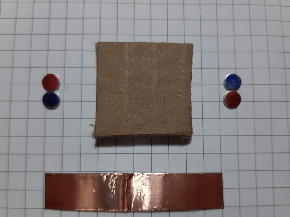
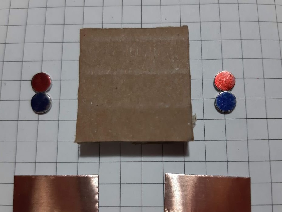
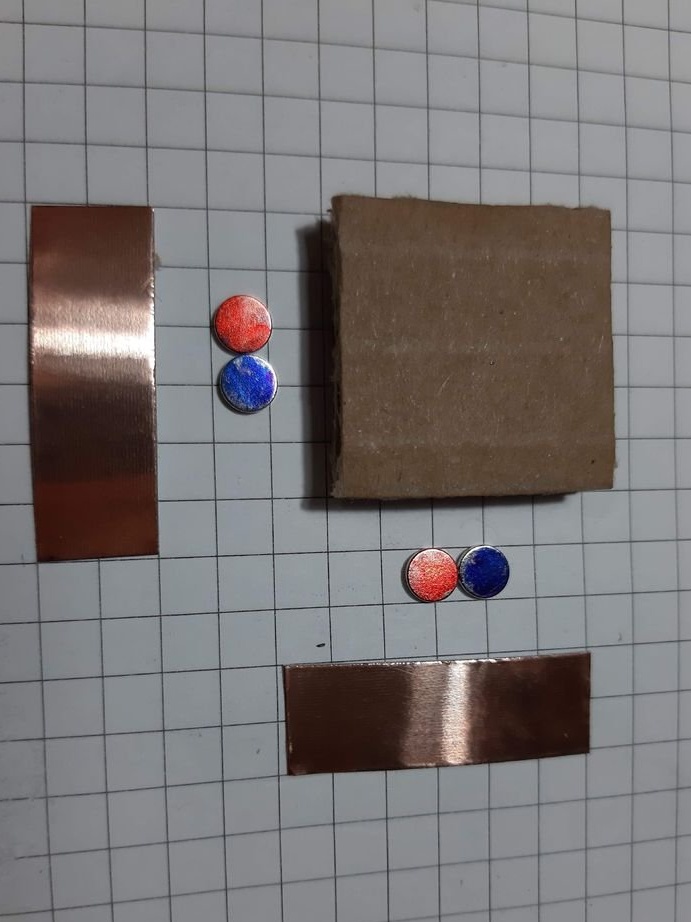
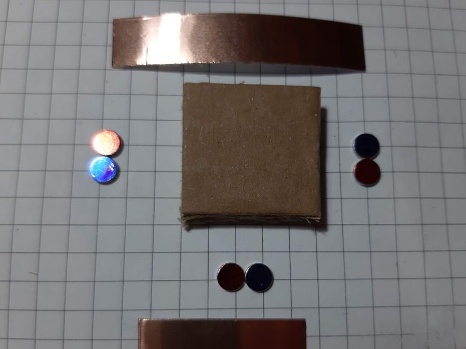
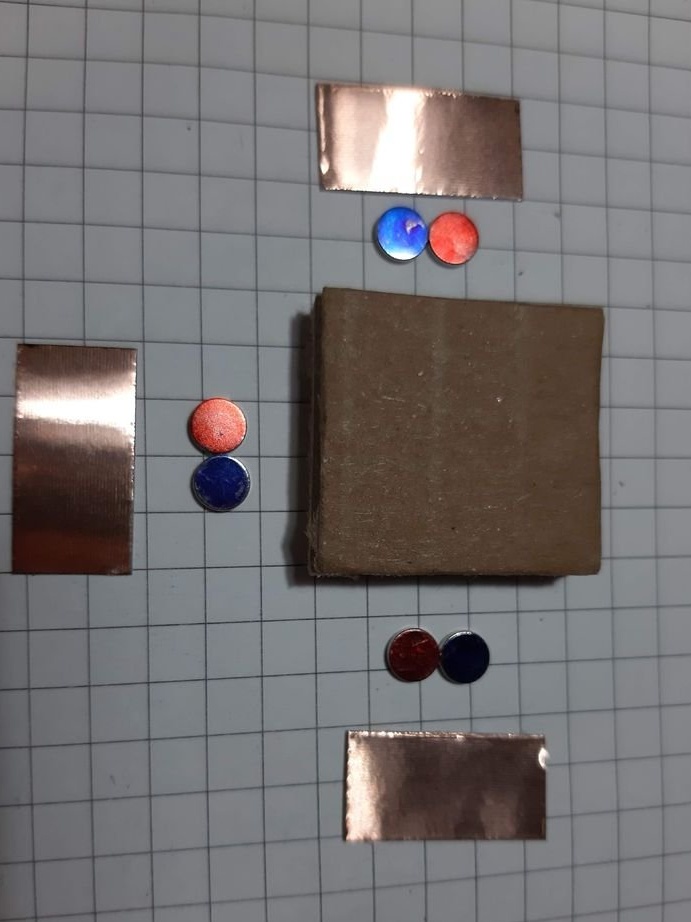
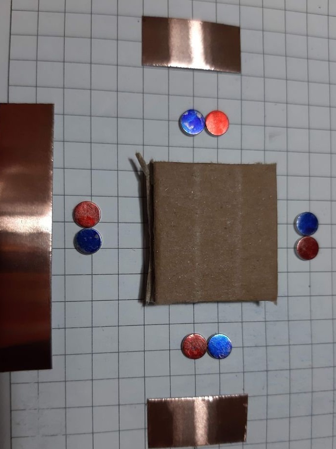
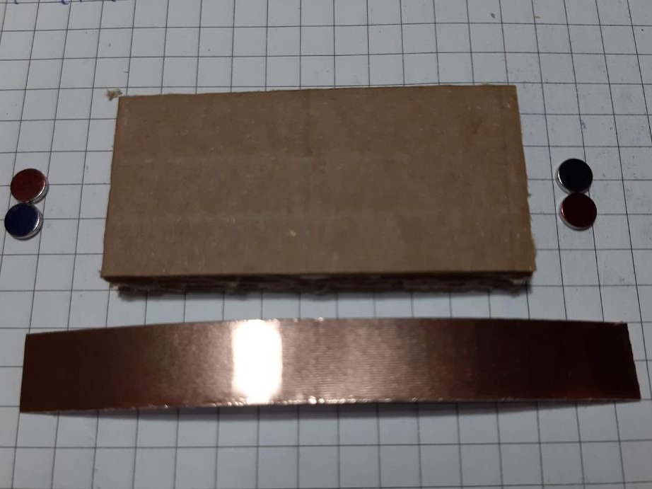
Group magnets in pairs, where each pair has one blue and one red side at the top. Remove the paper from the copper tape and stick it on the magnets, backing off about 5 mm from the bottom edge of the tape. Stick the tape on the cardboard square so that the magnets are on the side of the block. Orient the magnets as follows: clockwise, one side is blue-red, the second side is blue-red, etc. This construction ensures that no matter how blocks are deployed, the magnets will be in contact with different poles.
Step Five: Soldering
Corner and T-shaped blocks at the intersection of copper tape must be soldered.
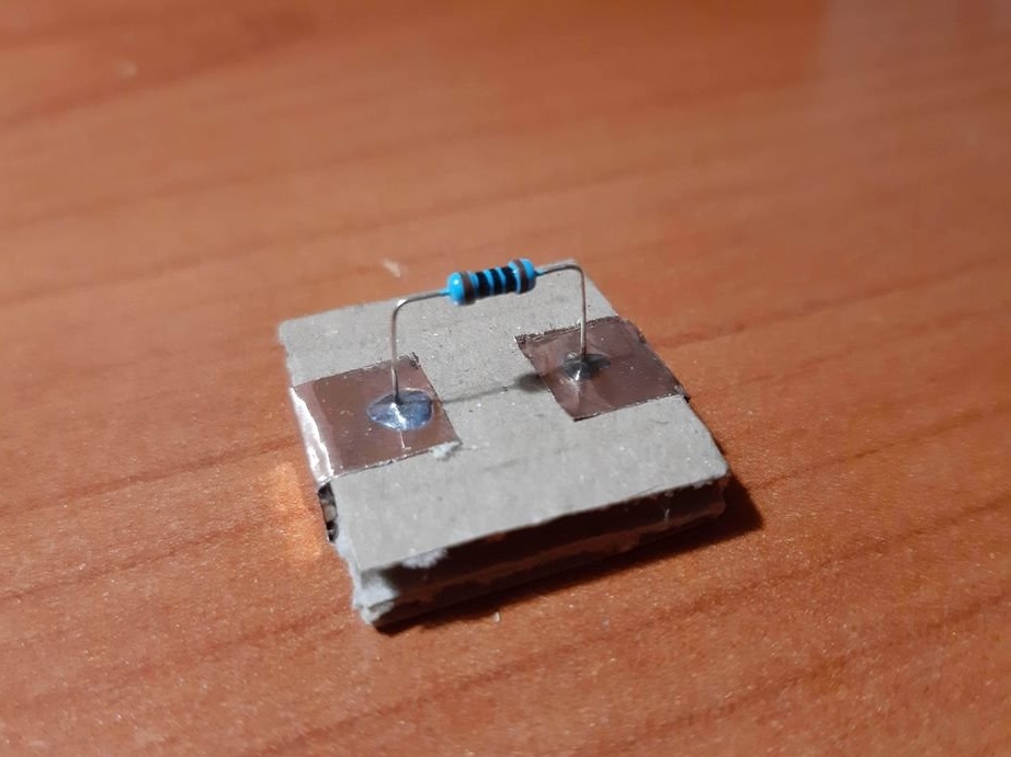
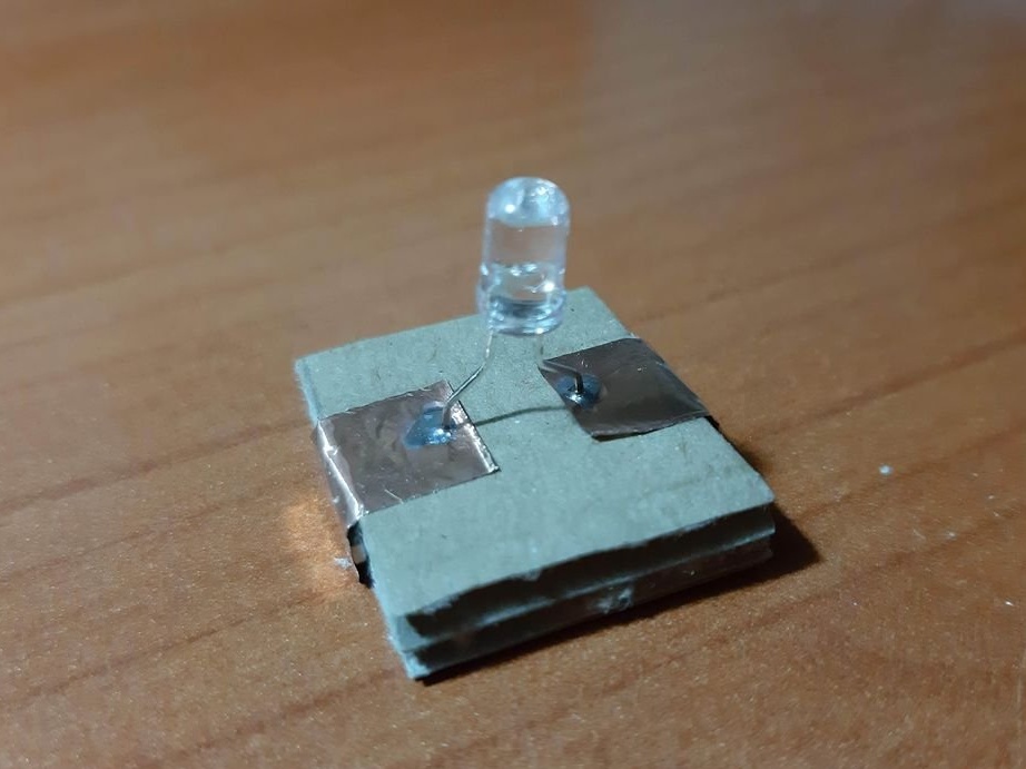
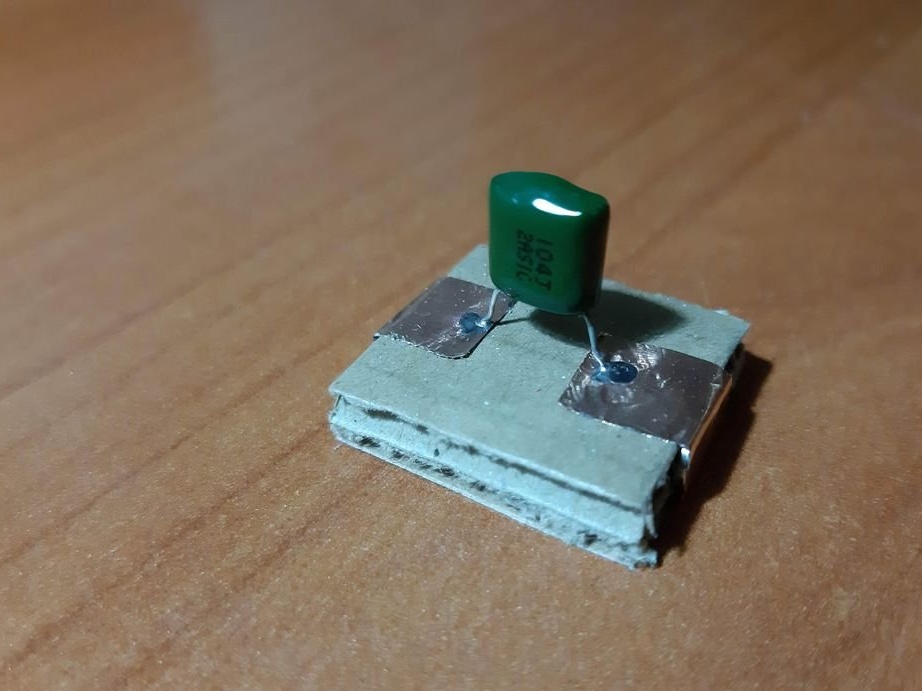
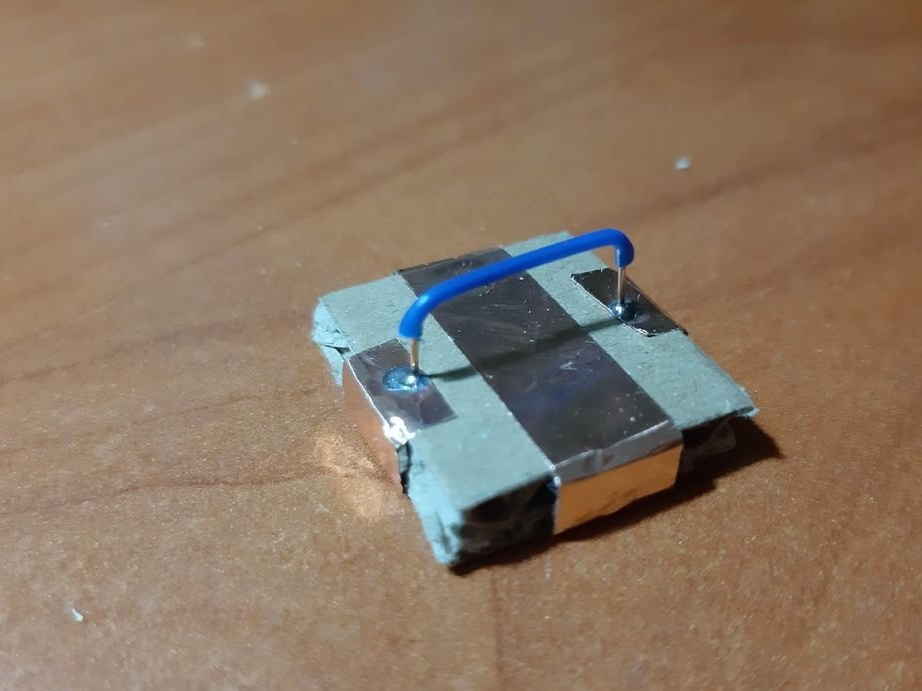
Step Six: Electrical Components
Using a needle, punch small holes in places where the findings of parts will be soldered. Cut the wires or legs to the desired length. Insert the legs into the holes and solder. For resistors and capacitors, write the value on the block. Indicate with symbols and colors other properties of the components, for example, the polarity of LEDs, etc.
All is ready. If you add more electronic components, then you can collect more complex circuits.