I haven’t done anything new for a long time. Well, I haven’t done a lamp based on LED rulers yet. I have already mastered soldering SMD components on an iron. So go ahead!
What is necessary:
1. LEDs 5630-0.5.
2. Grandma’s iron.
3. The drill.
4. The screwdriver.
5. Soldering iron.
6. Electronic components for the driver.
7. The case for the driver.
8. Chemistry for the manufacture of printed circuit boards.
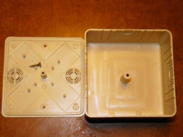
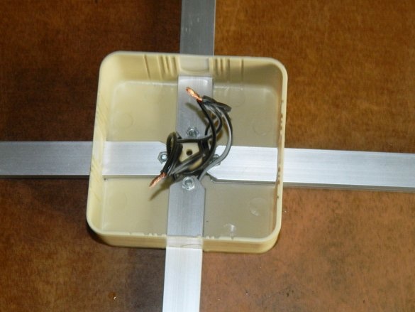
Let's start with the chandelier. I decided to make a spider chandelier. In Leroy, Merlin bought a mounting box for a future product for 46 rubles. The dimensions of the box are 75x75x32 mm.
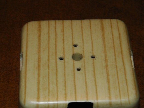
I drilled 4 rectangular holes with a cutting disc and drilled holes for fastening ø2.5 mm.
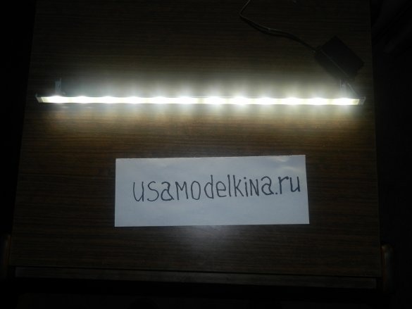
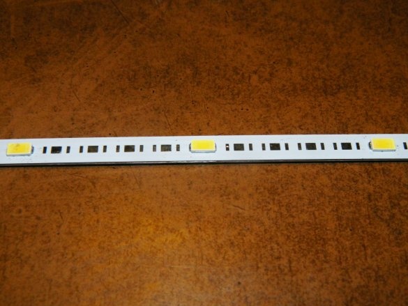
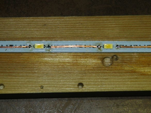
Then he began to solder. The line consists of an aluminum substrate, a dielectric layer and, in fact, conductive paths and soldering spots of LEDs. The dimensions of this line of 245 x 10 x 1 mm allow you to put up to 30 LEDs. I installed the LEDs through 4 positions, moving them from one edge to 3 positions. Only 6 LEDs per line. Then he soldered the gaps with a wire rod.
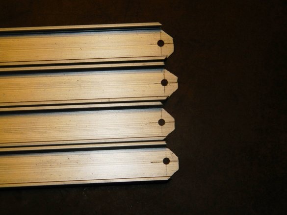
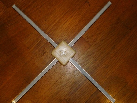
Cases with screens for LED strip just fit these lines. I cut 4 pieces with a length of 270 mm and sawed the ends under 45º with a drill only on one side, bearing in mind that there is a rod in the mounting box to screw on the cover. Then he drilled holes ø2.5 mm.
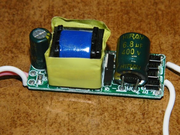
The finished driver PSM-430mA-6x2WS produces a current of 420-440 mA. He could provide with a parallel connection of the branches of the chandelier 100-110 mA for each branch.
Radial glued with heat-conducting glue to the ruler cases, fastened them with screws in the mounting box, inserted screens and put plugs.
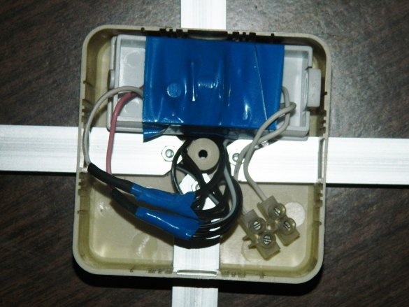
Soldered the driver so that all 4 branches were parallel. He insulated the soldering spots with a heat shrink tube, installed a contact block and a cover.
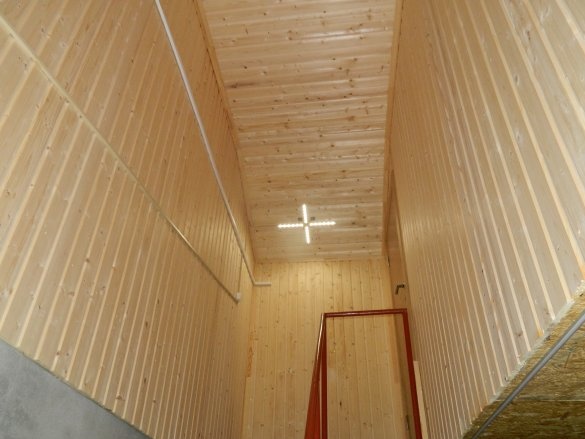
Here's a chandelier to the country turned out. Its power is about 8 watts. It looks quite original, and does not heat up at all.
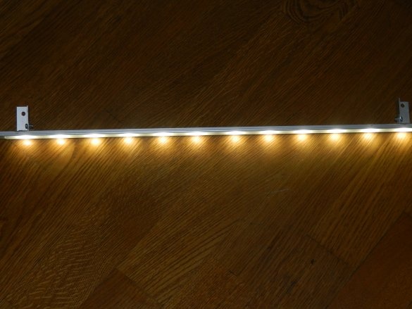
For the sconce, I also put 6 LEDs per line. Used 2 rulers. Rulers are connected in series. The driver will have to do it yourself.
The driver circuit is well known, you only need to calculate the quenching current capacity using the well-known formula. I got 2.2 microfarads x 630 V. I do not advise taking less than 400 V (but I only had 630 V).
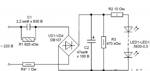
In Spint-Layot 6.0, I designed a circuit board sketch.
[center]
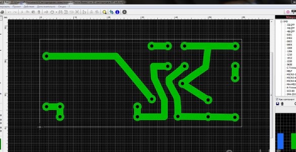
On an inkjet printer, I printed it on a tracing paper enclosed in an envelope, with maximum contrast and processed it with a building hairdryer.
On a suitable piece of fiberglass (pre-treated with a fine sandpaper with Seth), applied a layer of POSITIV 20.Then he put it in the oven for half an hour at a temperature of 100ºС. Then I set it to light for 40 minutes. under the ultraviolet lamp. To facilitate the passage of ultraviolet radiation, the TRANSPARENT 21 printout was sprayed on beforehand. The board was developed in a caustic soda solution for 15 seconds. Board etching - in a solution of ferric chloride for about half an hour. Then I used "liquid tin." An hour later, the conductors were covered with a layer of tin. After unsoldering all the components, the driver was ready.
[center]
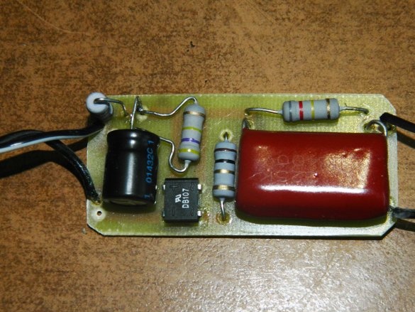
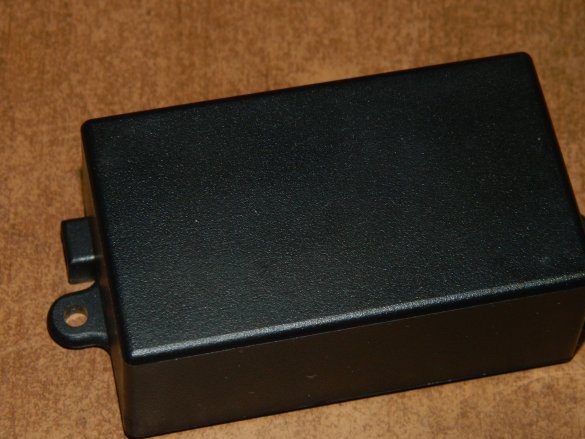
It turned out fine - the driver was included in the box G1013. This box is good in that it has ears for fastening.
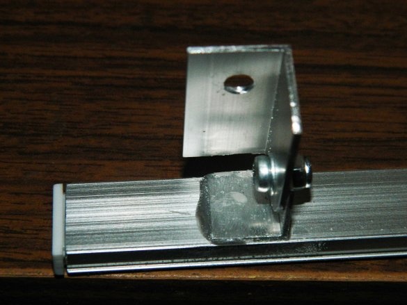
It remains to make ears for attaching a sconce. I made them from duralumin corners and put them on cold welding.
It turned out pretty well.
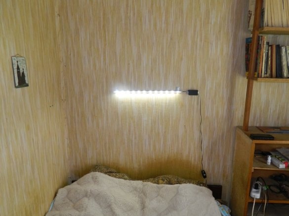
Sconce over the bed in the house.
Chandelier illuminates the upper platform in front of the entrance to the second floor the garage.


