It is proposed to consider a manufacturing option. electronic speed controller for a DC motor with an operating voltage of 24 V.
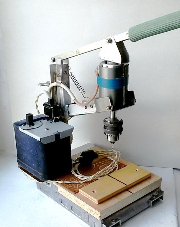
The proposed design of the engine speed controller is designed to change the speed of rotation of the tool on a drilling machine, the manufacture of which is described in the note "Drilling machine - rhomboid". However, this device can be used for power control in other designs.
The need for adjusting tool revolutions is caused by the following reasons. Changing the processed material, diameter and type of tool requires a change in cutting speed. For example, drilling plexiglass or some thermoplastic plastics, at optimal conditions for drilling metal, will only lead to the melting of the processed material in the cutting zone and its sticking to the drill. Drilling, reaming and countersinking of the same hole also requires different revolutions for high-quality surface treatment. Increasing the diameter of the drill requires a proportional decrease in the number of revolutions. In addition, sometimes reversing the direction of rotation of the tool is required. For the elementary fulfillment of these conditions, it is proposed to manufacture an electronic speed controller.
Making the engine speed controller.
1. The source data.
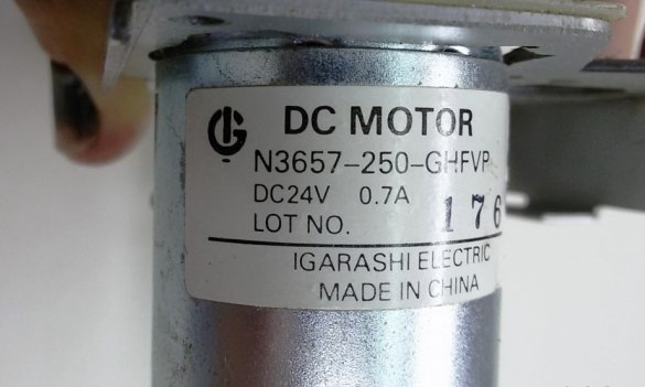
In this example, a 24-volt DC motor (0.7A) is used on a drilling machine.
For the operation of this electric motor, an appropriate power source is needed.
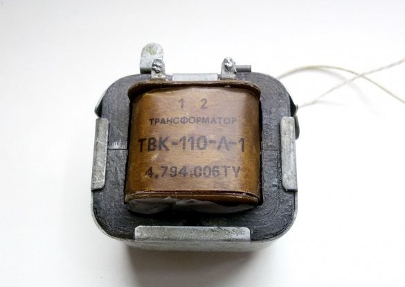
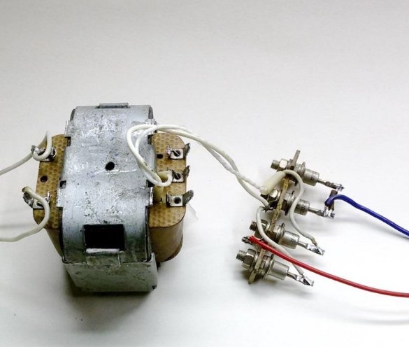
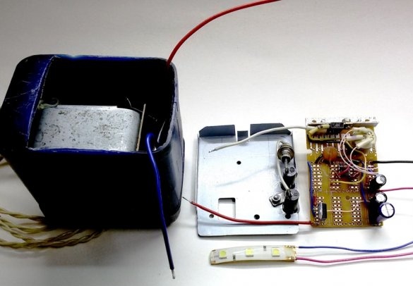
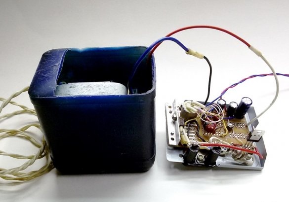
The voltage and current required for the operation of the engine can be provided by the vertical scan transformer TVK-110L-1, taken from an old TV. It has small dimensions and mass (ШЛ 20 х 32) and from the secondary winding it is able to produce a current of 1 A with a voltage of 22 ... 24 V. In this case, the rectified voltage will be about 30 V, but with an increase in the current consumption, the output voltage will decrease slightly.
2. The manufacture of a rectifier.
Since with a possible sharp braking of the processing tool, surges of the current consumed by the motor up to 1.5 ... 2.0 A are likely, for the manufactured rectifier it is necessary to use diodes with a margin of current limit. It is advisable to use diodes with an operating voltage of more than 30V and a limiting current of more than 2.0A.
In the considered version of the regulator, the optimal KD202D diodes (200V - 5.0A), which are at hand, are used.
From the selected diodes, we will assemble a bridge rectifier and connect it to the secondary winding of the transformer. We power the transformer from the mains and check the output voltage.
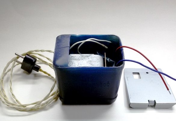
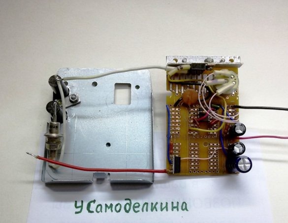
3. Making a case for the device.
It's time to place the electrical part of the speed controller. The following options are possible. In a separate case independent of the machine, in a case permanently installed on the machine, and also integrated in the machine structure (for example, in the machine table).
Since the proposed design is a power regulator for various devices, taking into account the prospects of its possible further use, it is advisable to manufacture this device in a separate mobile case. The manufacture or purchase of a suitable case will depend on your wishes and capabilities. As an option, a plastic bottle from chemicals with overall dimensions of 90 x 70 x 90 mm was used in the design in question.
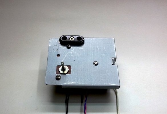
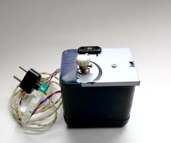
The container has partially cut off the upper part. The resulting window is closed with a decorative panel made of a metal sheet with a thickness of 0.4 mm. The ribs formed after bending on three sides of the shelves on the workpiece give the panel sufficient rigidity to work. When installed in a structure, the panel also gives the housing extra strength. The panel is equipped with a socket for the output voltage, a power regulator, a board with an electronic circuit (bottom).
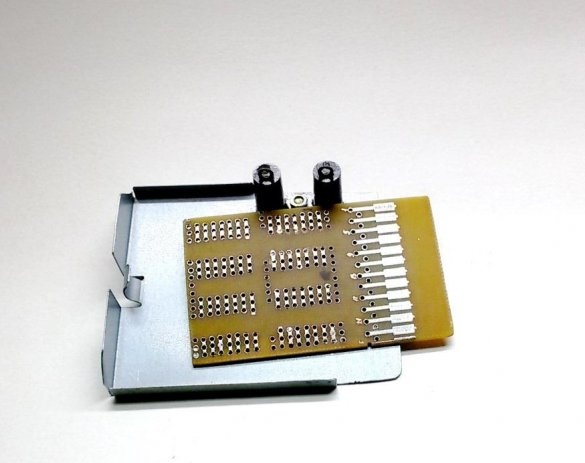
According to the size of the window in the case, from the universal circuit board, a working board is cut out to accommodate the electronic circuit of the controller.
4. The electrical circuit of the regulator.
On the Internet you can find many options for circuits for regulating the speed of a DC motor. The simplest and most stable circuits are based on the NE555 timer. They require a minimum of components, practically do not need to be configured and are quickly assembled. Therefore, we will not strive for originality, we will perform an electronic speed controller based on a proven generator circuit with a timer NE555, according to the figure below.
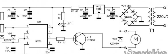
The controller circuit is based on DA1 - an imported integrated timer NE555 (domestic analogue - KR1006VI1). The design of the timer is a multifunctional integrated circuit (IC). It is often used in various devices (electronics, computer technology, automation). The main purpose of this timer is to generate pulses with a large range of the repetition period (from microseconds to several hours).
The given controller circuit on the NE555 timer allows you to control the motor speed using pulse-width modulation (PWM).
In this method, the supply voltage to the motor is supplied in the form of pulses with a constant repetition rate, but at the same time their duration (pulse width) can be controlled. With this control method, the transmitted power and engine speed will be proportional to the pulse duration (duty cycle of the PWM signal - the ratio of the pulse duration to its period).
The principle of operation of the PWM signal generator on the NE555 timer is repeatedly and in detail described in the relevant publications, which can be found on the Internet.
The regulator generator operates at a frequency of about 500 Hz. Its frequency depends on the capacitance of capacitor C1. The pulse duration will be regulated by a variable resistor R2. The signals from the output of the PWM signal generator, through the current amplifier on the transistor VT1, control the machine motor. By increasing the width of the positive pulse entering the base of the transistor VT1, we increase the power supplied to the DC motor, and vice versa.The pulse duration, and therefore the engine speed, can be changed in the range from 0 to 95 ... 98%.
Reverse the direction of rotation of the tool can be done using the toggle switch installed on the panel. But to simplify the design, this function is performed by turning the plug (pole change) in the socket on the panel.
Instead of the composite n-p-n transistor KT 829A, a field-effect transistor or an optocoupler of the corresponding power can be used.
The regulator will be powered from a 220 V network and have a 24 V output regulated by power. The supply voltage of the NE555 timer should be in the range of 5 ... 16 V, in the circuit it will work from a stabilized voltage of 12V. This controller circuit can also work from another power source within 24 ... 30 V.
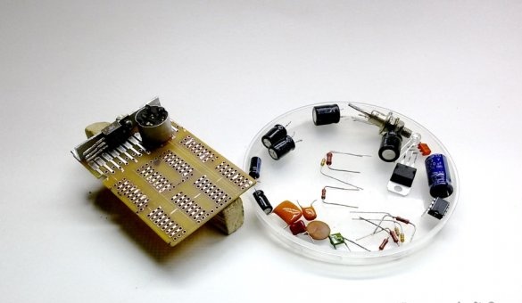
5. The complete set of the device.
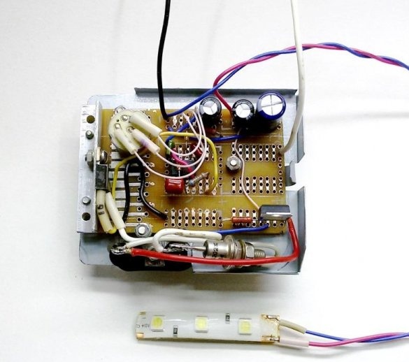
We complete the device with parts according to the above diagram. The output transistor VT1 and the stabilizer VR1 are installed on small radiators. In the given design they are made of an aluminum corner.
6. Checking the operation of the generator circuit.
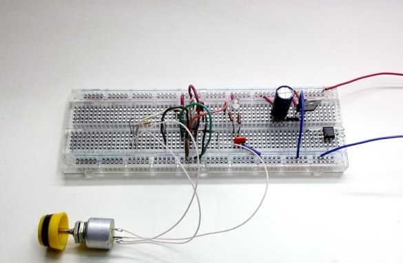
On the Internet there are many similar variants of the generator circuit on the NE555 timer, but the values of parts in different circuits differ by tens and hundreds of times. Therefore, to simplify the manufacture and debugging of a working circuit, it is advisable to pre-assemble it on a universal circuit board.
We collect the generator circuit. To the timer output (pin 3), we connect the base of the n-p-n transistor KT315. In the circuit of his collector, we turn on the indicator LED through a 1kΩ limiting resistor. The emitter is connected to the minus circuit. We feed the generator circuit from a stabilized 12V power supply. Choosing the values of the parts, we control the correct operation of the generator by the glow of the LED.
The control LED can also be installed directly to the timer output (pin 3), but keep in mind that the NE555 timer has an output current of up to 200 mA. Close domestic analogue KR1006VI1 allows an output current of up to 100 mA.
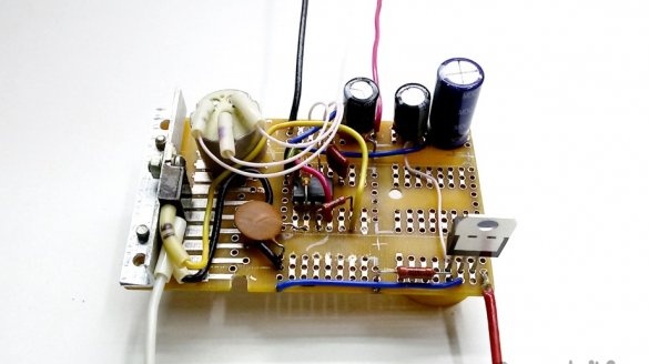
7. Installation of the speed controller circuit.
We carry out the layout of the board - we place the parts on the radiators, a variable speed control resistor, electrolytic capacitors. We drill holes in the board for mounting parts and fixing the board to the device panel. We carry out the installation of the regulator circuit on the working board.
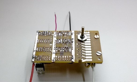
8. Assembling the engine speed regulator.
We collect all the nodes of the speed controller. We fix the board on the device panel using a thin PCB gasket to isolate the board contacts from the metal panel. The output of the regulator is connected to the outlet located on the panel. Also, to its terminals, in the opposite direction, we solder the VD3 diode. It will dampen the self-induction pulses of the motor winding. This diode must withstand operating voltage and current of at least two times the performance of the motor.
The role of the regulator operation indicator will be performed by one element of the LED1 LED strip, at a voltage of 12V. Place (glue) it on the shoulder of the engine mount, above the drill chuck, for simultaneous with the indication of the illumination of the treatment area.
9. Finalization of the design of the drilling machine.
Work on the manufactured machine showed the need for some refinement of its design.
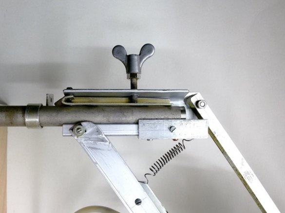
An additional plate is installed under the fixing screw in height, which allows you to distribute the clamping pressure over a large area, eliminate jamming and facilitate sliding of the suspension base on the machine stand.
At the suggestion of the commentator on the control of the optimal position of the tool relative to the workpiece, an adjustable stop was made and installed. It is mounted at the top of the suspension base and serves as a stop for the upper suspension arm. The emphasis is adjusted so that the drill chuck and suspension arms cannot fall below 2 mm from the zero line. In the position on the stop, the drill is installed in the chuck until it touches the machine table.So it will automatically work in the optimal zone of 4mm, with a minimum lateral displacement of 0.01mm.