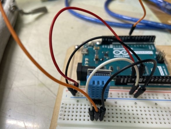
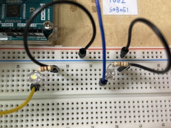
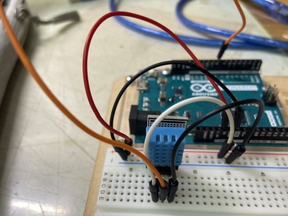
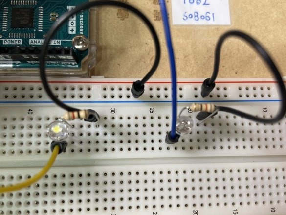
In the manufacture of the test, temperature and humidity during fermentation play an important role. To control these parameters, the master made a control device.
In the manufacture of the following components were used: Arduino, computer, LED, wire, DHT11 (temperature and humidity sensor).
DHT11 has three pins. The right side is the negative electrode, the left side is the positive electrode, and the middle is the signal wire. The 5V sensor power is connected to the Arduino. The signal wire connects to pin 8 of the Arduino.
Next, you need to connect two LEDs, red and yellow. Connects them through resistors. The cathodes are negative, and the anodes are at 11 and 12 pins of Arduino.
Next, you need to download the code. The code is given, as in the original article. If necessary, you need to translate and substitute your values.
無效 設置 () {
}
#include “DHT.h”
#define dhtPin 8 // 讀取 DHT11 數據
#define dhtType DHT11 // 添加 DHT11
DHT dht (dhtPin , dhtType) ; // 初始化 DHT 傳感器
無效 設置 () {
pinMode (12 , 輸出);
pinMode (11 , 輸出);
Serial.begin (9600) ; // 設置 鮑 率 9600
dht.begin (); // 啟動 DHT}
無效 循環 () {
float h = dht.readHumidity (); // 讀取 濕度
float t = dht.readTemperature (); // 讀取 攝氏 溫度
float f = dht.readTemperature (true); // 讀取 華氏 溫度
如果 (isnan (h) || isnan (t) || isnan (f)) {
Serial.println (“無法 從 DHT 傳感器 讀取!”);
返回; }
Serial.print (“濕度 :”);
Serial.print (h);
Serial.print (“% \ t”);
Serial.print (“攝氏 溫度 :”);
Serial.print (t);
Serial.print (“* C \ t”);
Serial.print (“華氏 溫度 :”);
Serial.print (f);
Serial.print (“* F \ n”);
delay (5000); // 延遲 5 秒
如果 (abs (t-30) & lt; = 2)
{
digitalWrite (12 , HIGH);
digitalWrite (11 , LOW); }
其他
{
digitalWrite (11 , HIGH);
digitalWrite (12 , LOW);
}
}
You can download video for viewing the installation process on this the link.


