Glad to welcome you again. So, today we will make a plotter. A small one from a computer DVD or CD. This plotter is a modification of my laser engraving machine, also small, also from computer DVD or CD. Therefore, in order not to write the same thing, I will refer to my other homemade. If you already have a laser engraving machine, manufactured according to my instructions, your work will be reduced to the manufacture of a working tool - a pen holder or a marker. This holder will be placed in place of the laser. Those who did not make such machines will have to open two instructions.
Video demonstration:
We will use:
- DVD-ROM or CD-ROM (total 4 will be required, if there is a machine - 2)
- Plywood, chipboard, OSB 10 mm thick (6 mm plywood or chipboard is also suitable)
- Arduino Uno (or any compatible compatible boards. Nano, Micro, Esplora - will not work)
- Arduino CNC Shield v3
- Servo SG90
- Platform universal Tamiya 70098
- A4988 stepper motor drivers with radiators 2 pcs.
- Power supply for 5V, 3A
- connecting wires
- Connector 2.54 mm Dupont
- Eletrolobzik, drill
- Thin elastic
- Drills for metal or wood 2, 3, 4, 5 mm
- Screw 3 x 20 mm or 4 x 20 mm
- Marker, best thin
- Nuts, grovers and washers 4 mm
- Hot glue
- Wood screws 2.5 x 25 mm, 2.5 x 10 mm
- Soldering iron, solder, rosin
Step 1. Assembly of the basis for the plotter.
As I said, you have to turn to another my instructions.
Follow steps 1 and 2. Just disassemble it will be necessary 4 DVD or CD drive. Two drives disassemble it will be the axis X and Y.
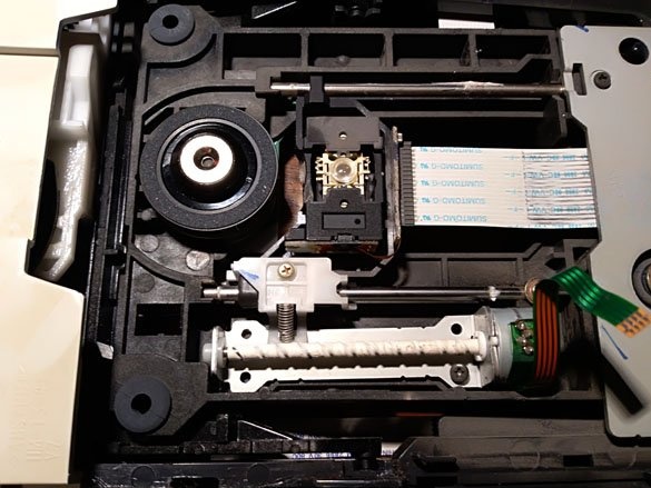
When parsing CD drives, you may come across an unpleasant surprise. There will be no stepper motor inside. They look something like this:
As you can see in the photo, in these there is a regular DC motor. These can be used to make a marker holder or pen.
In the same instruction, the third step is the preparation of the power supply, you can use that step. But we'll talk about the power supply later.
The engraver manufacturing manual version 1 has the fourth step, “Step 4 Joystick for manual operation.” - you do not need to do it. The joystick was needed with the first version of the firmware. In the second and all subsequent, control commands are sent through the serial port.
Step 2 Making a writing holder.
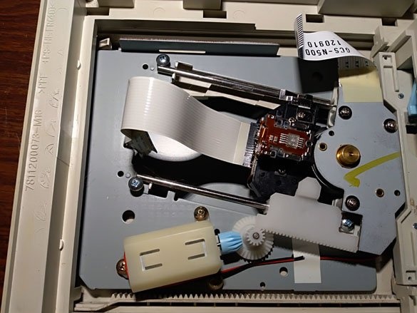
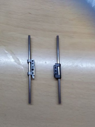
Having disassembled a couple of DVD-drivers, we open two more. Of these two drives, we need only two axles and two bearings.
But two drives are necessary, because the frame with two bearings in one drive is only one, and we need two.Bearings are often integral with a moving carriage. Therefore, most of the carriage must be cut off or bit off, the main thing is not to damage the bearing. We take out the components we need:
We take the platform from the set "Platform universal Tamiya 70098". Of course, this platform is used to build a tracked model, but I have remained idle since I used other materials. The platform is well suited for the manufacture of various parts, it has holes, and it is easy to cut.
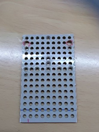
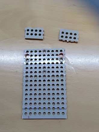
You can replace this platform with another material, for example, plywood 4 mm thick. Only in this case will it be necessary to make holes in the plywood for mounting the axles, mounting to the machine and the clamping plate. Whatever material you take, we cut out rectangles from it: 80 x 48 mm is the base, two 24 x 15 mm are the axles, 23 x 23 mm is the clip for the pen (marker), 23 x 23 mm with a protrusion on one side by 10 mm.
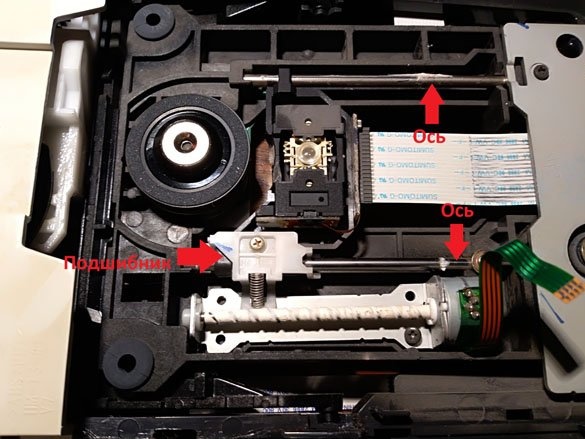
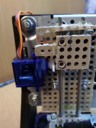
Picking up a hot glue gun, we assemble our mechanism as follows:
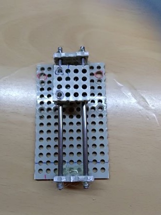
Let me explain: on the base above and below, perpendicular to the base, glue the rectangles 24 x 15 mm. Then we insert the axis with the bearings, the axis is also fixed at the edges. We attach a 23 x 23 mm rectangle with a protrusion to the bearings (I have no photo of the protrusion, I forgot about it when I cut it, I will stick the protrusion later).
Before installation, you should have the following fastening on the machine:
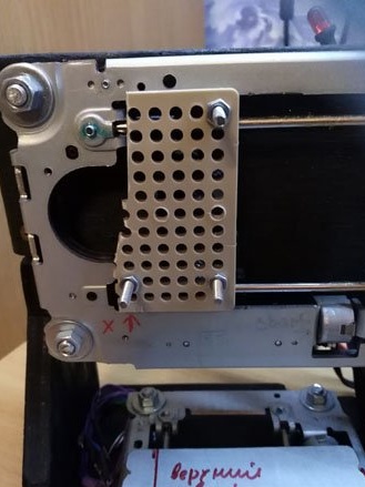
How to make it is described in detail in the instructions "Laser engraver from old DVD-Rom."
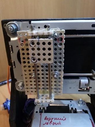
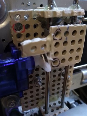
We put our mechanism on the machine, fix using nuts:
Since I forgot about the protrusion, we glue it to the rectangle glued to the bearings:
We take the servo drive and glue it to the base, on the left side, approximately in the middle. Before fixing the servo, make sure it is set to 90 degrees.
And now we take a small stretch of gum, thread it into the outermost hole of the servo lever, then thread it into the hole of the protrusion or just throw it on the protrusion:
The writing instrument will be lifted by the lever from the servo, while the servo will be in the 90 degree position. When the lever goes down (the servo position will be 180 degrees), the pen or marker will go down after the lever, and slightly pressed due to the elastic tension.
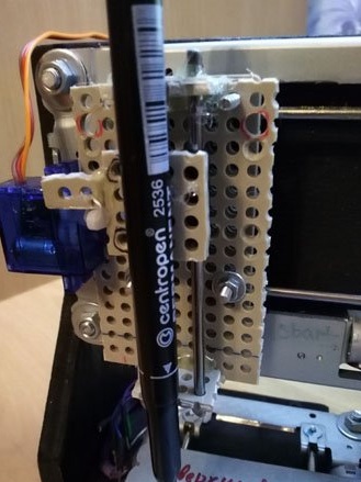
Who can’t wait to check the plotter at work, it can simply stick a marker on hot melt adhesive:
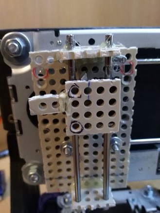
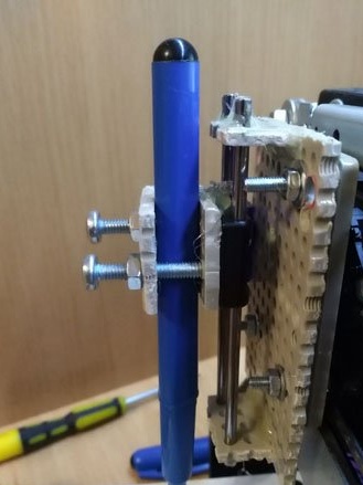
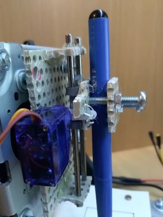
Who else has patience - we take bolts, nuts, a clamping rectangle and assemble this design:
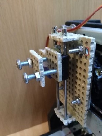
We insert the marker between the rectangles and clamp using nuts (you can use your hands, this will be enough to hold the marker):
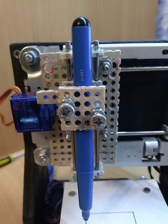
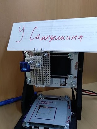
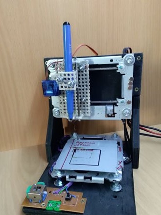
To make the whole structure better visible, a couple more photos from different sides:
That's all with mechanics. We turn to electrics and software.
Step 3 Electrician.
We will use electrics from the second version of the laser engraver - "Laser engraver from DVD version 2.0».
We carry out almost everything in the third step of the above instructions. We do not need the transistor from that instruction, it was needed to turn on the laser, the servo drive works without a transistor, it has its own controller. A test LED will also be redundant.
In the fourth step of the same instruction, “Step 4 Setting the current limit of the motors.”, Describes the process of setting the current of the stepper motors. When the laser was working, there was no additional resistance for its movement. At the plotter, the writing instrument will come in contact with the paper, which will create resistance to movement due to thorns. Therefore, the current strength is better to slightly increase. We do everything according to that instruction, we change only the measurement parameters:
Vref = Imax * 8 * (RS)
Imax - current of the stepper motor
RS is the resistance of the resistor.
In the case of a plotter:
RS = 0.100.
Imax = 0.55
Vref = 0.55 * 8 * 0.100 = 0.44 V.
As a result, between the variable resistor of the stepper motor driver and GND there should be a voltage of 0.44 V.
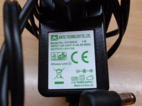
For power we need a 5 V power supply.It is best to take a 3 A block, preferably with a margin. The input voltage from 12 V to 36 V is written on the CNC Shield, but since our stepper motors are designed for 5 V, we will power the CNC Shield and, accordingly, the drivers are also 5 V. This circuit has been personally tested by me and repeatedly, everything works well. The power supply is something like this:
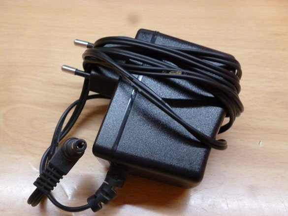
With the following features:
Starting from GRBL version 0.9, the connection pins “Z-limit +” and “spindle enable” were swapped. Therefore, the signal wire from the servo is connected to the "Z-limit +". Plus, from the servo to +5 V (power must be taken directly from the power supply, and not from +5 V located on the Arduino), GND to GND, respectively.
You can also use a computer power supply. How to do this is described in “Step 3 Preparing the Power Supply.” my instructionsLaser engraver from old DVD-Rom»
Step 4 Firmware and control program.
To get started, download the Arduino IDE, as always with official site
To control the plotter, we will use GRBL, modified to control the servo drive. Go to the following link and download archive entirely
We rewrite the unpacked archive into the “libraries” folder, which can be easily done in the folder with the Arduino IDE installed. We launch the Arduino IDE, go to the “file” - “examples” - “grbl-servo-master”. Click "download", wait for the sketch to finish loading. To control the plotter, we will use the LASERGRBL program. Download and install it
The program interface is intuitive, everything is simple there.