

Friends, hello. I want to introduce you homemadewhich I did about a year ago. This is a band saw on wood. Her design is not very complicated, and with the proper skills, almost every master with a small set of tools can repeat it.
So let's go.
From the tool you need: Welding, grinder, jigsaw, drill, crowns, hand tools.
Materials: Plywood, corner, rod on the axis, bolts and nuts, studs, electrodes, motor, belt, paint, profile pipe, chipboard. Maybe something forgot? Understand the campaign.
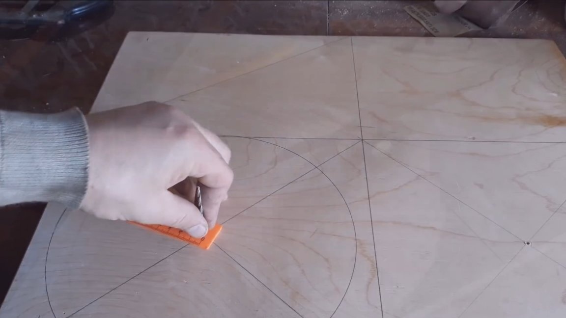
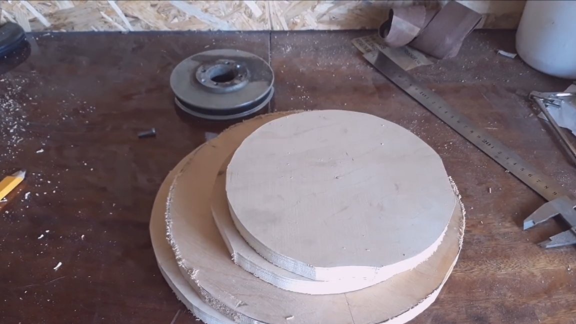
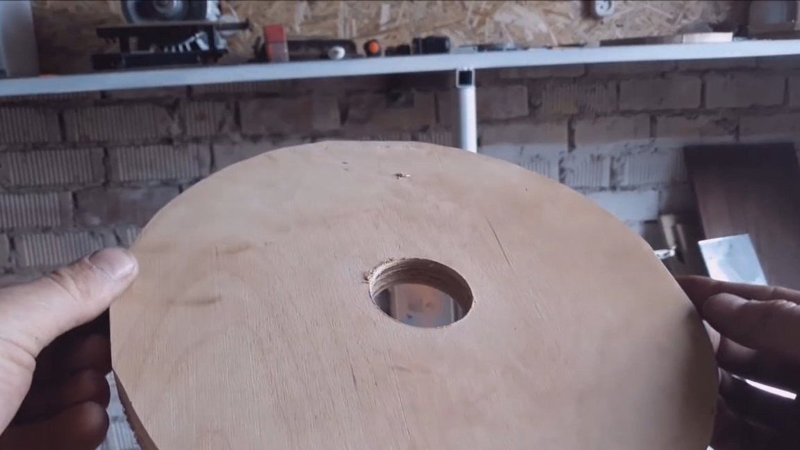
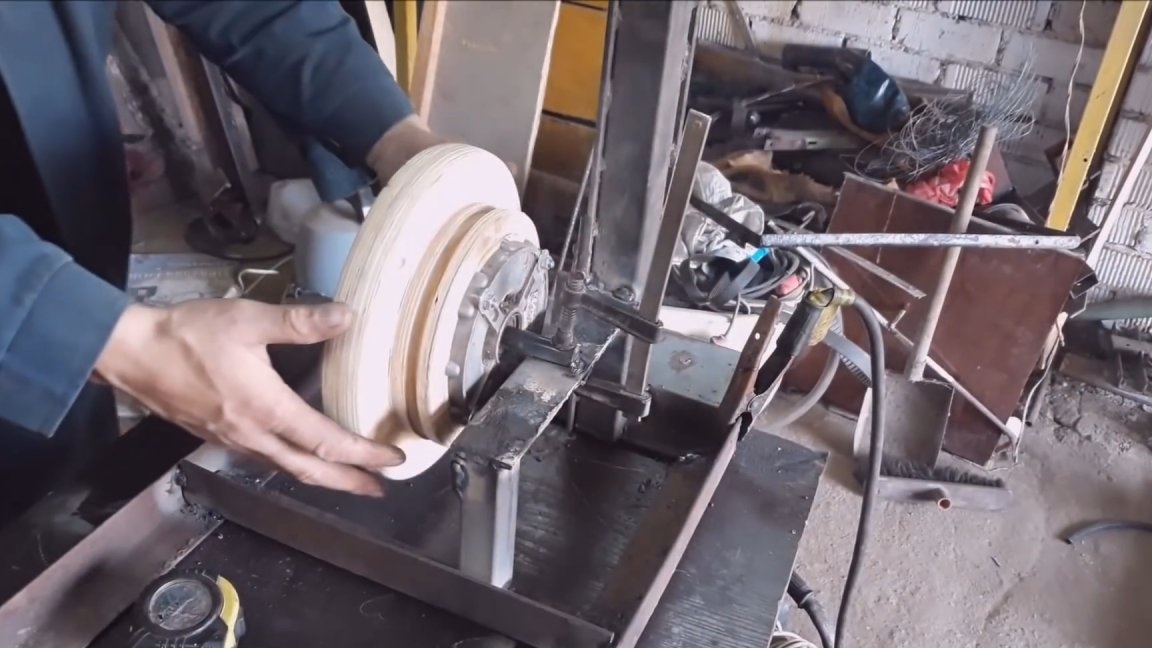
The band saw is a metal frame on which two wheels are mounted. A saw band is put on these wheels. One of these wheels is driven, and is driven by an electric motor. Let's start with the wheels. I decided to make the wheels from plywood. Since there was no plywood of the required thickness, I had to make two halves 16 mm thick. I saw the tape was 1920 mm. To prevent the web from breaking much, the diameter of the wheels is 200 mm. To make two wheels, you need to cut 4 pieces. In my case, the thickness of one was 16 mm. The lower wheel should be driven by the engine, so I sawed two more workpieces of a smaller diameter. It turns out that the upper wheel consists of two parts, and the lower one of four.
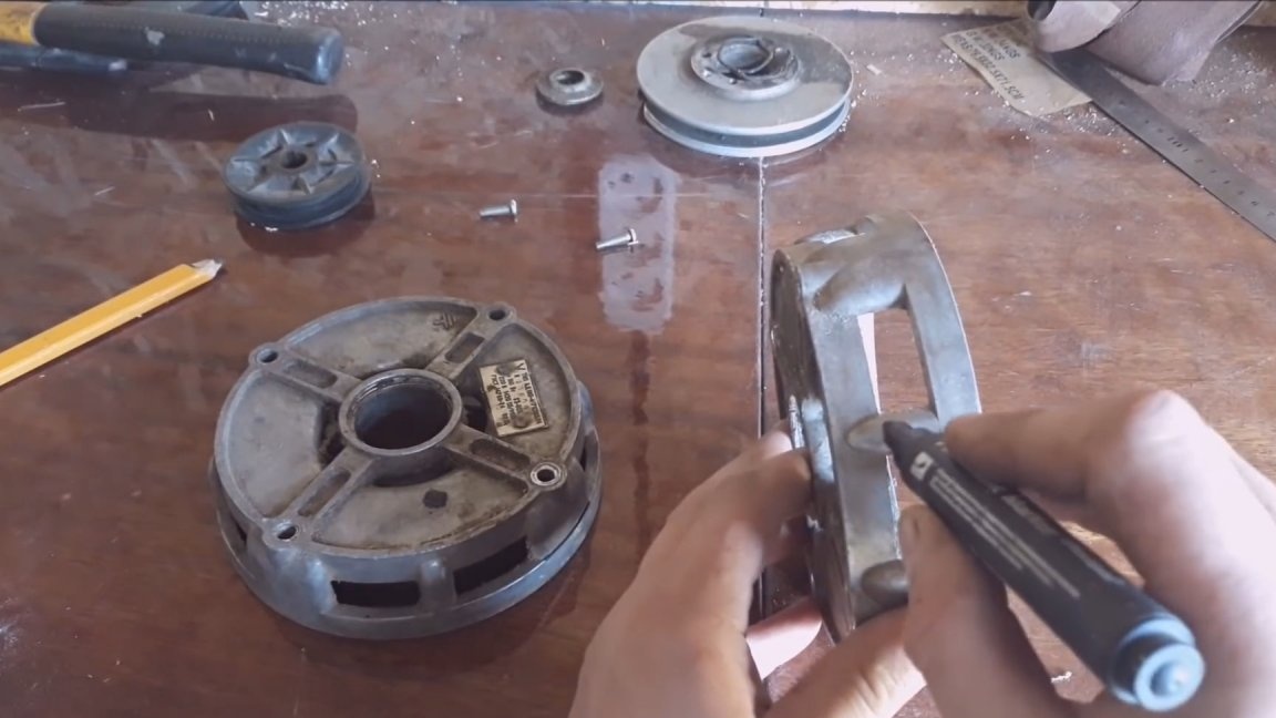
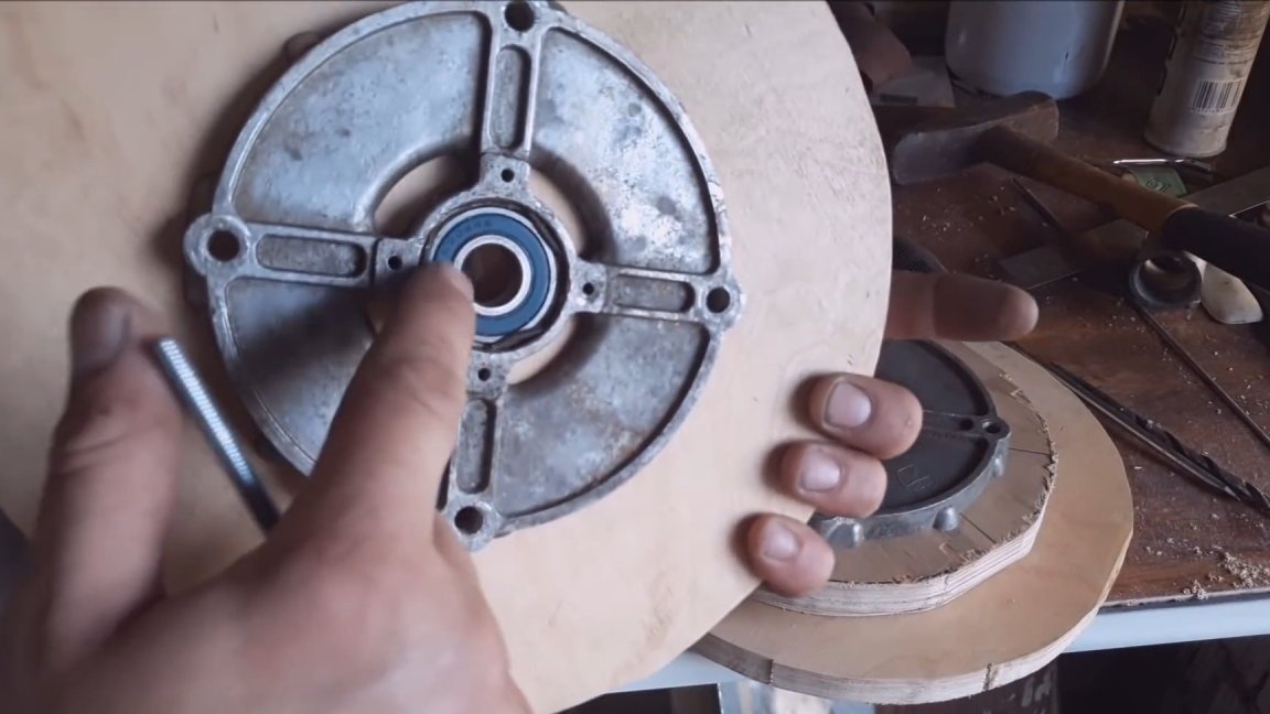
Next we need side covers from the engines of old washing machines. They will serve as bearing housings. Cut off all unnecessary as shown in the photo. In the discs with a crown of 40, we make the central holes. Next, we fold our package, install lids on the sides and drill 4 holes with a drill. I wanted to glue all the plywood discs at first, but then I thought that it would be superfluous and a screed for 4 M8 studs would give good stiffness. The same procedure must be repeated with the upper wheel. In principle, the wheels are ready, but there is one caveat. They are terribly crooked and hit very hard. I thought for a long time how to align them and came to such a decision. There is a threaded hole on the covers, such as M4. Having rummaged in stocks, found on a pulley from an old washing machine.
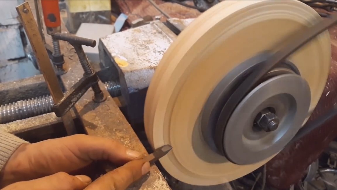
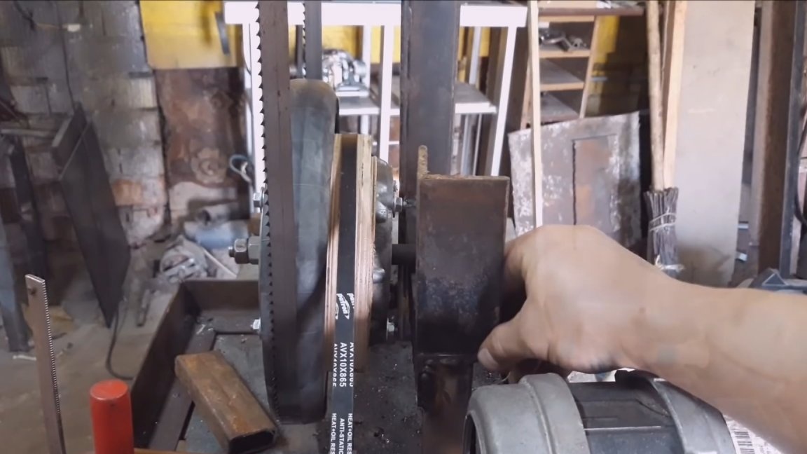
I drilled a hole and screwed it to the lid. Then he took the axle, clamped it in a vice, put a wheel on this axle. The drive was carried out by a polishing machine through a belt on which a pulley was also installed. He built an improvised handyman. He made a cutter out of the old file, and picking up speed, they are good, they are regulated, and slowly this miracle is leveled.A cutter was prepared from a square file along the profile of the belt, and a groove was made in the lower wheel for the belt. In the same way he processed the upper wheel. There is one caveat. The plane on which the tape will run should be semicircular. This will help to better hold the tape, and also prevent it from escaping from the end of the wheel. When the wheels are made and machined, you can begin to manufacture the frame.
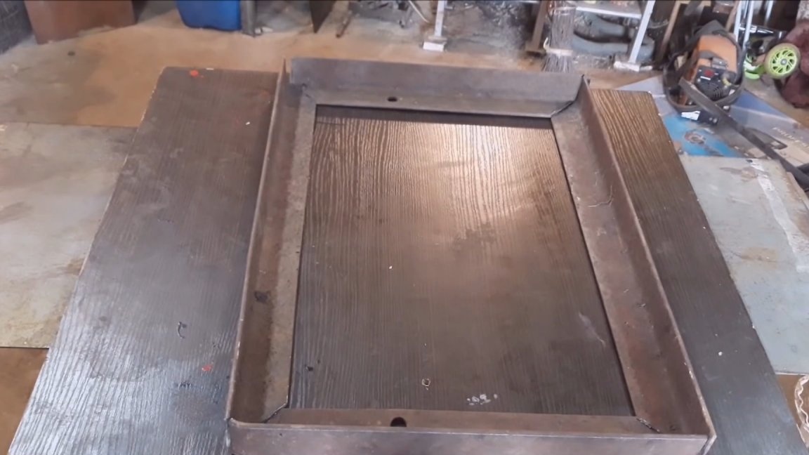
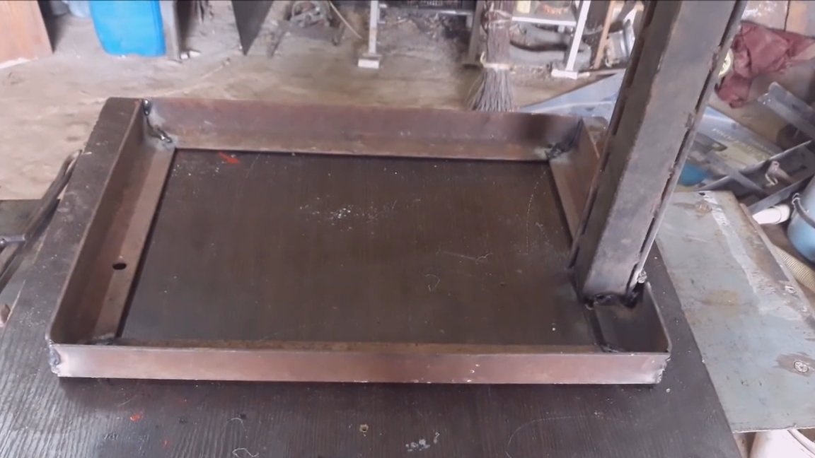
A rectangle-shaped base was welded from a 50 × 50 corner. On one of the short sides a stand was welded perpendicularly, consisting of a 40 × 40 profile pipe and reinforced with a 50 angle.
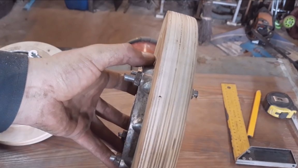
I sawed everything in place, so I won’t say the exact size. On a frame in the middle I welded a cross-beam, to it a small rack and the upper cross-beam to which the wheel axle will be attached. I think everything will be clear in the picture. If something is wrong, below the text there will be links to the video, there you can see everything in detail. The axis decided to stupidly weld to the upper cross member. By the way, he turned the axes on his TV-16. I also forgot to say that between the covers there was an expansion sleeve made of a water pipe. I adjusted the diameter of the axis to the inner diameter of the bearings and cut a thread from one edge.
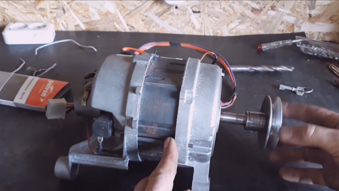
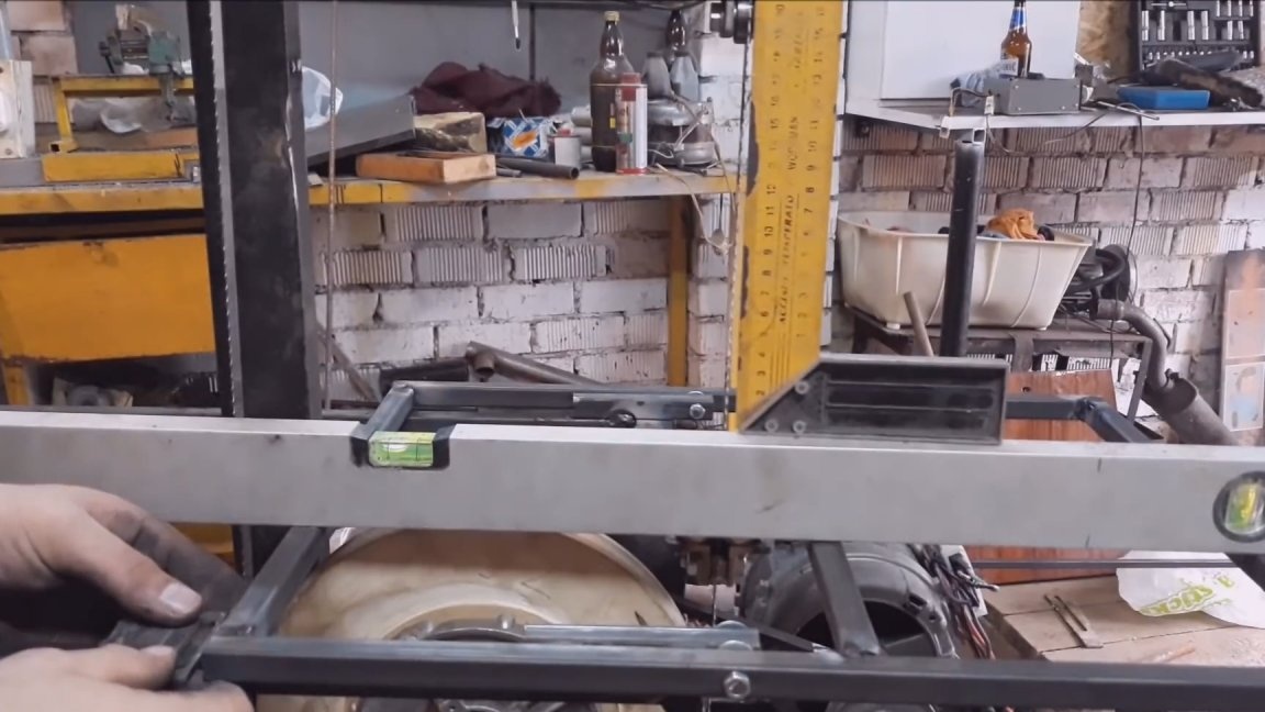
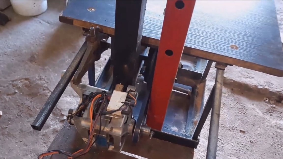
The wheel is put on the axle and rests on the ledge, on the other hand, it is tightened with a nut through the washer and locked. The axle was first picked up by welding, then the wheel section, put a level to it and aligned it with the frame and the upright. Then the axis was finally welded. On one side of the frame, he temporarily mounted a motor and threw on a belt. A motor by the way from a washing machine is an automatic machine with a capacity of about 400 watts. The channel has a video for the manufacture of a controller based on Arduino to control such motors. This controller allows you to adjust the speed with power support. Also in the near future I will post an article here with a detailed description of the assembly of such a controller. Wait a bit. I plugged the whole thing into a power outlet and slowly added speed. Everything is spinning, nothing is shaking, bearings are not heating.
Now proceed to install the upper wheel. It's a little more complicated here. This wheel should move in two planes. Up and down to pull the tape and release the tension to replace it. Also, the wheel should tilt. This is necessary to adjust the tape so that it runs strictly in the center of the wheel. The solution to this problem looked like this.
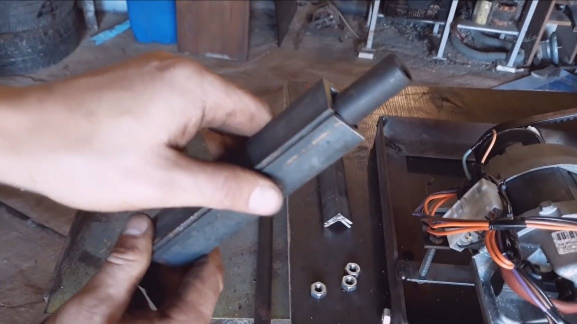
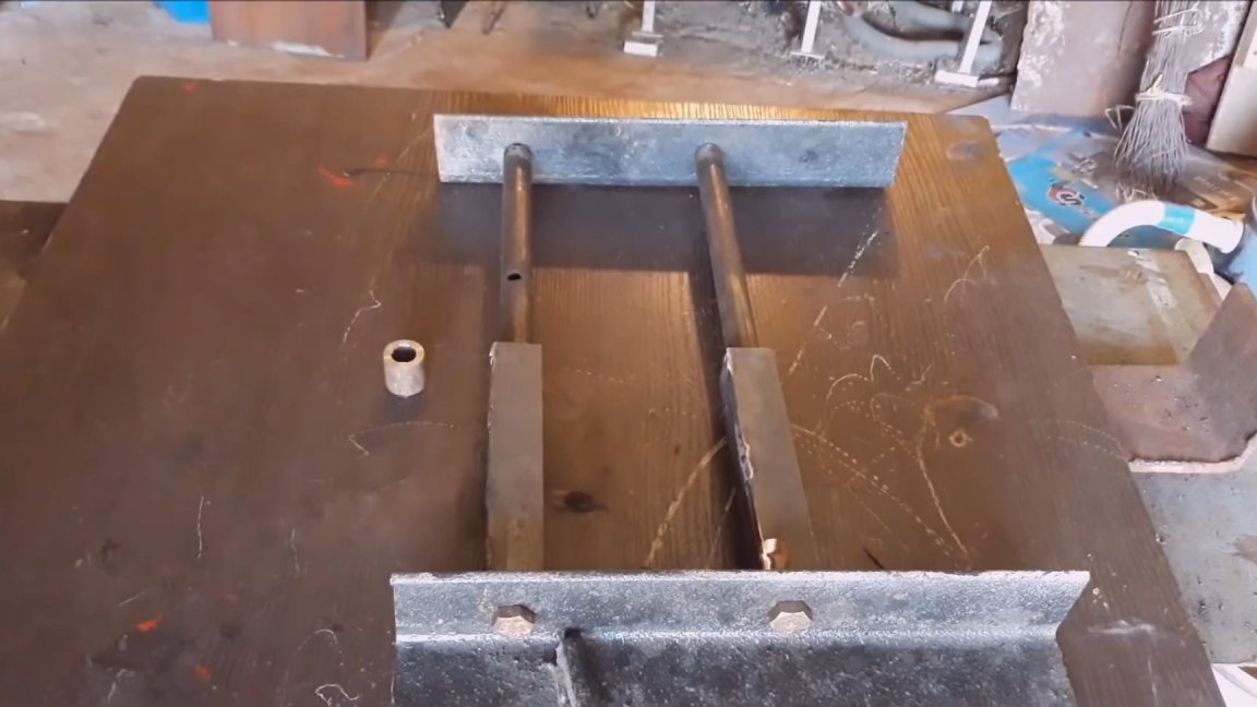
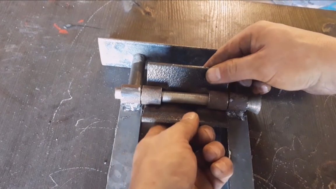
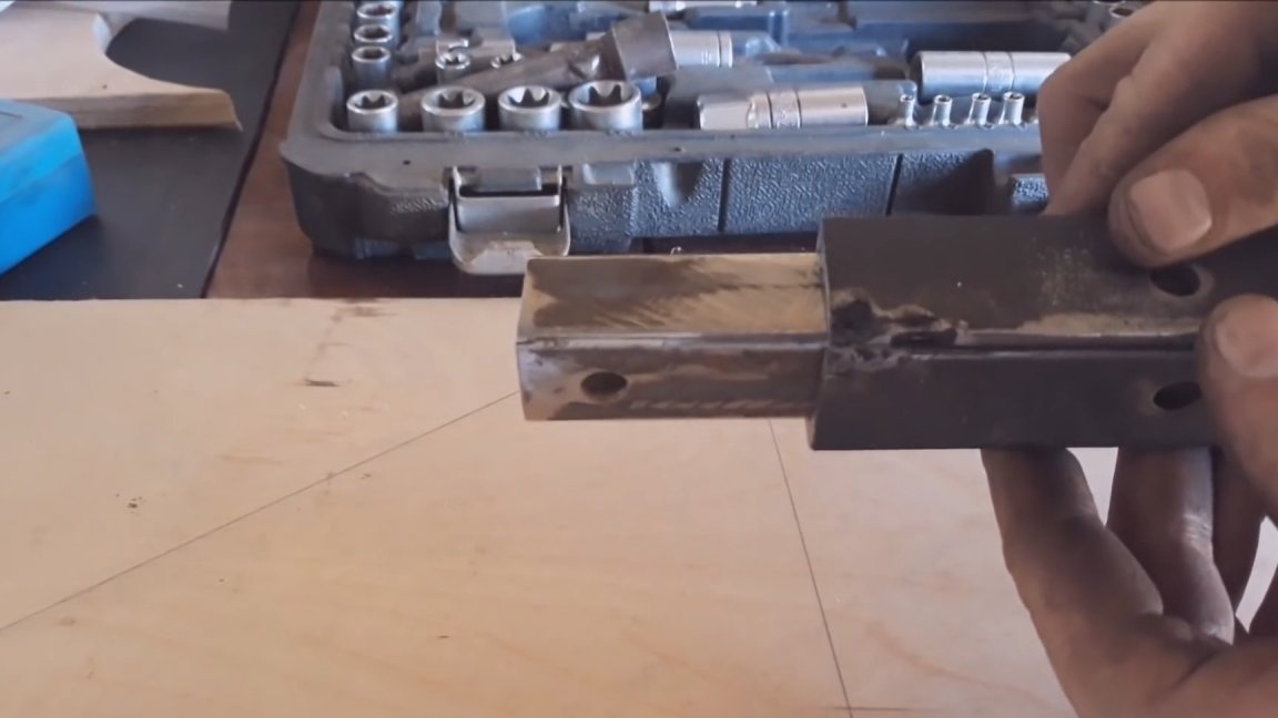
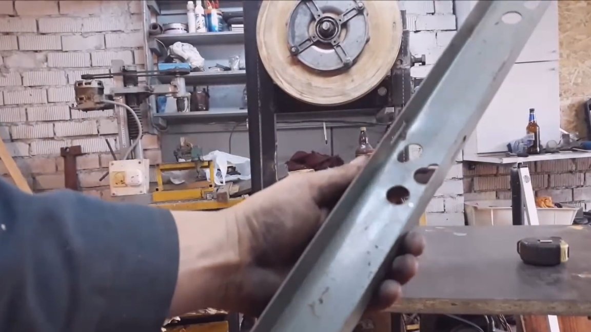
I took two pieces of tubes about 30 cm long. I welded nuts at the ends. In two pieces of 50 angles, I drilled holes at an equal distance and screwed the tubes with bolts. It turned out something like parallel guides. Now from two corners we cook something similar to a profile pipe, having previously inserted the pipe there. The resulting moving elements. We connect them with a jumper. Now we cut 4 pieces from the same pipe. Two of them are welded along the edges, below the movable frame, this is important, and the remaining two are welded inside the corner.
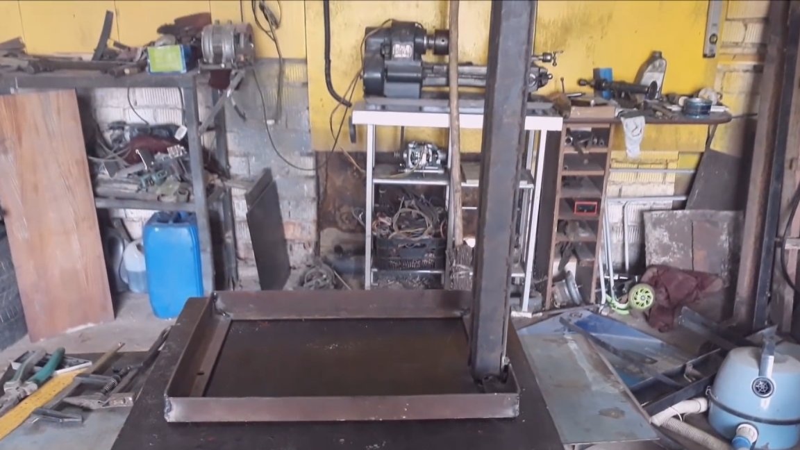
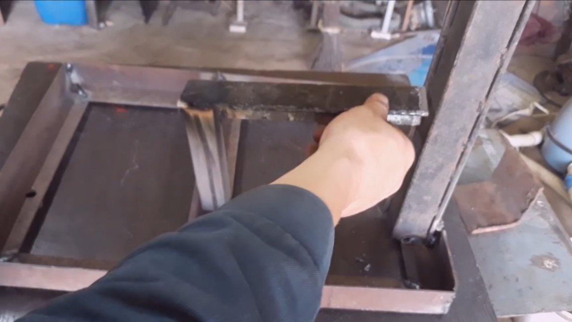
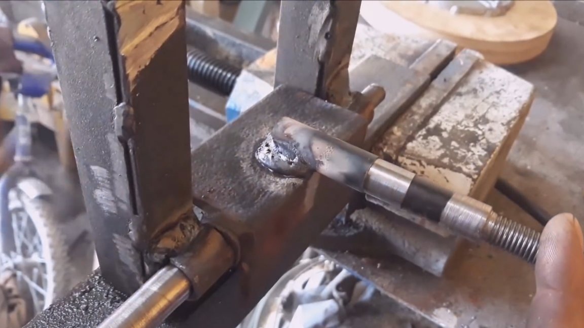
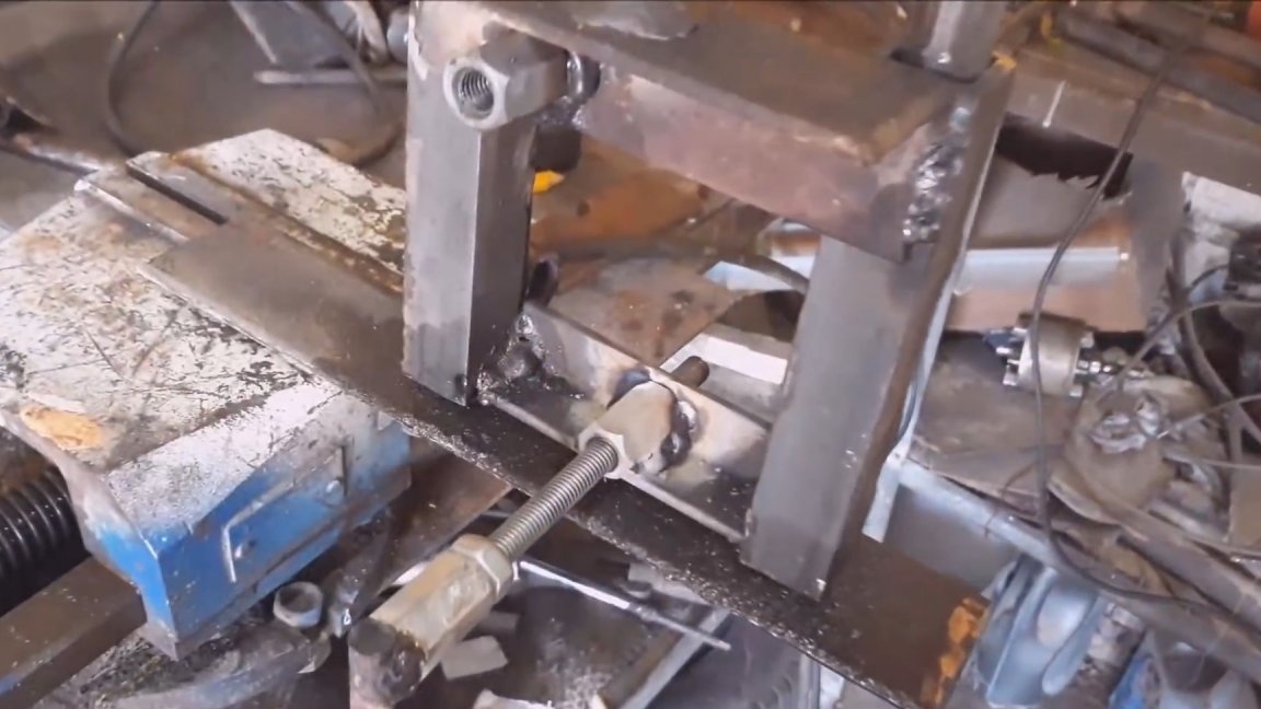
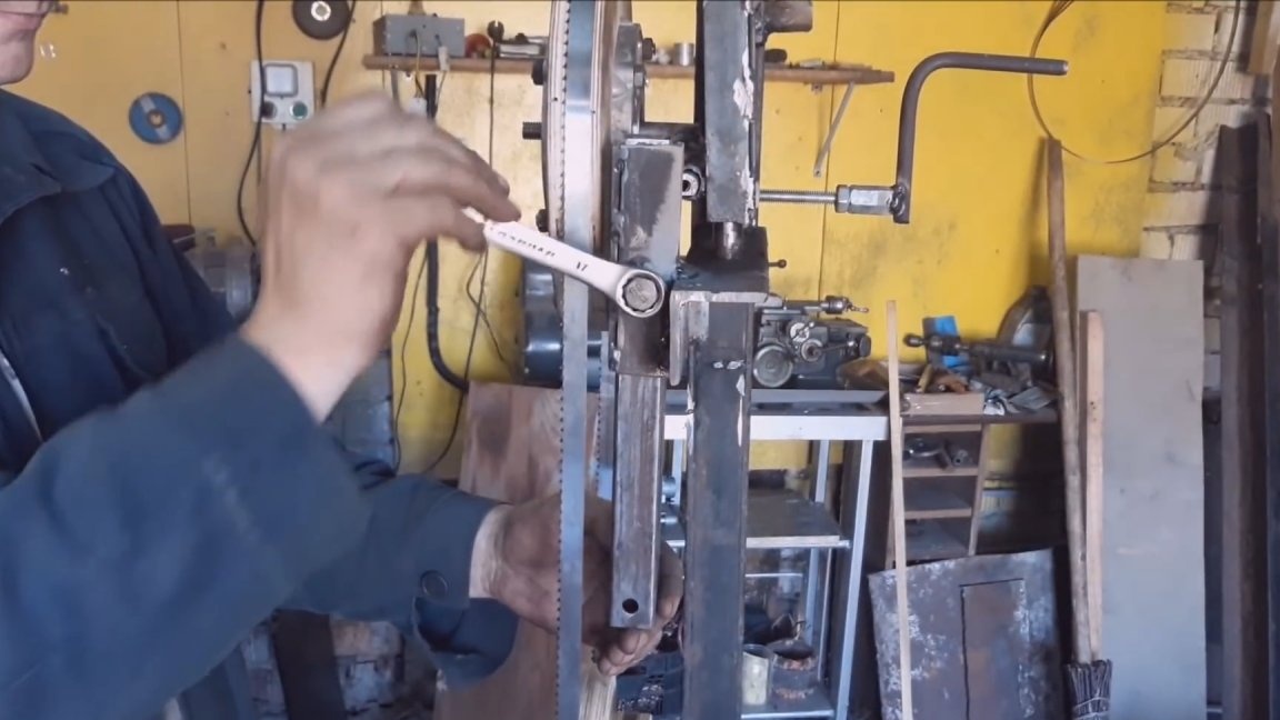
Through the tubes we pass a suitable axis. The axis of the upper wheel will be digested to this movable corner. The top of the movable frame is also fastened with a corner. A hole will be drilled here and an elongated nut welded. A long hairpin will be screwed into it, which will pass through the upper corner. Washers and two locknuts will be installed there on top and bottom of the corner. The handle is wound on a hairpin. This will allow the carriage to be moved for tension. A jumper is also welded on the bottom side of the carriage, a hole is drilled and a bolt is screwed in. It abuts against a corner with an axis and allows you to adjust the inclination of the upper wheel. How hard it is to write so that it is clear. When everything is ready, this design can be welded to the rack. I did so. The upper and lower corners, on which the tubes are held, initially took longer, because I had no idea how it all came together. I applied a level to the ends of the wheels and set the wheels strictly vertically relative to the rack. That is, the saw blade should move parallel to the stand. Further noted the upper and lower corners and cut off.
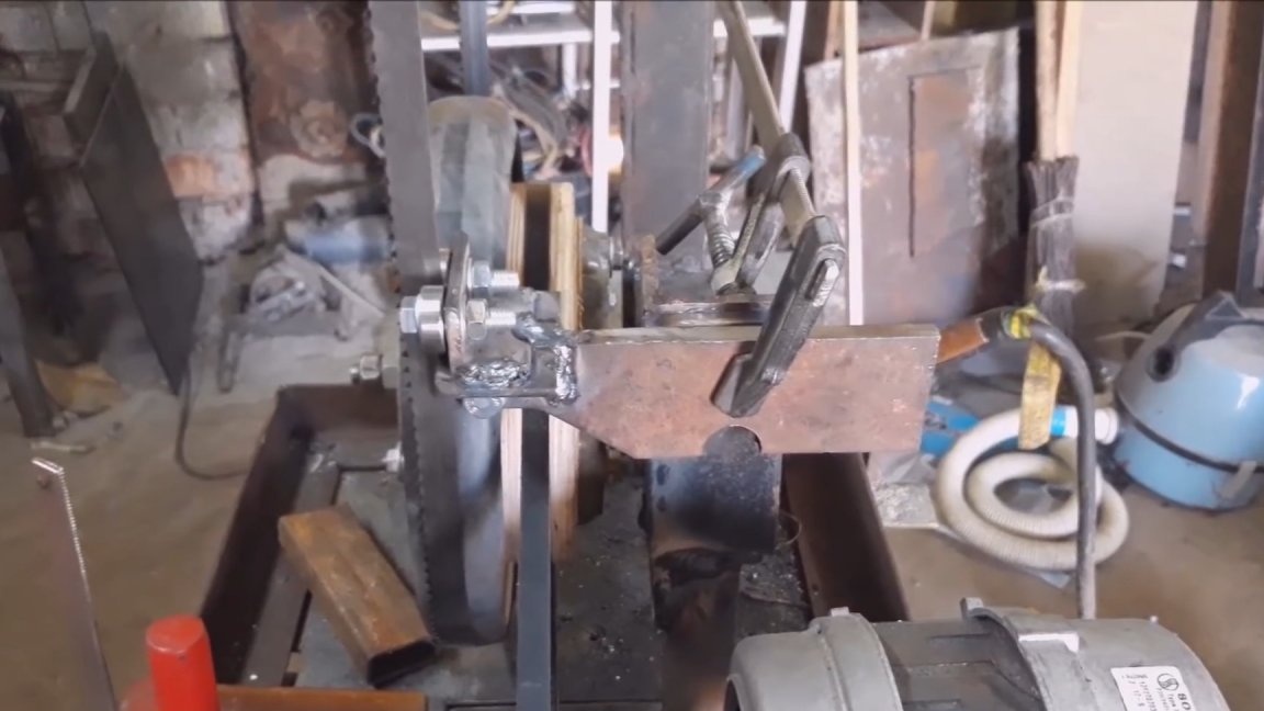
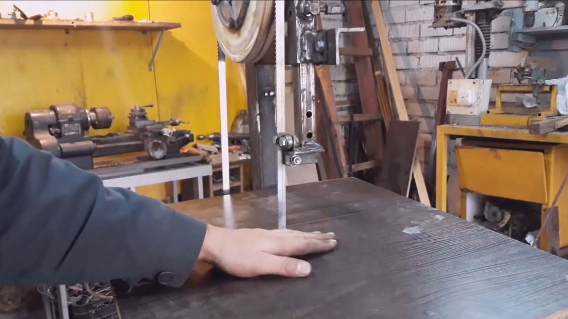
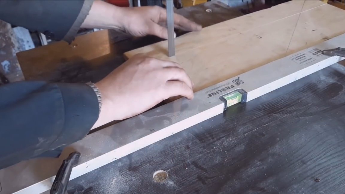
Now I applied the level to the ends of the wheels and fixed it with clamps.I used the level on one side of the wheel, and on the other a flat rail. So we will achieve the position of the wheels in one plane. When everything is set up, you can weld the upper wheel frame to the center pillar. After welding, you can throw the saw band and try to turn it on. It is better to stand behind the machine so as not to get injured. Before starting the wheels, be sure to manually scroll. At first, the tape will fall off, but you will understand how to properly adjust it. And only after it will stably run in the middle of the wheel, you can turn on the engine. If everything goes well, continue on. If the tape still tries to fly off the wheels, it means that somewhere it was improperly welded or not adjusted.
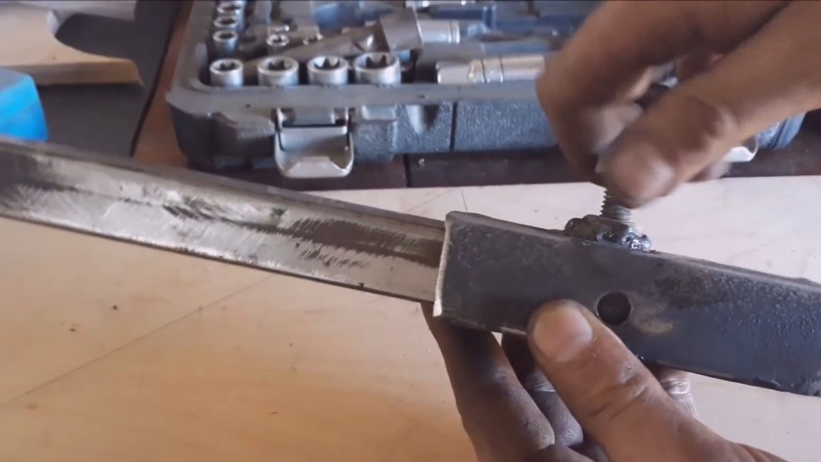
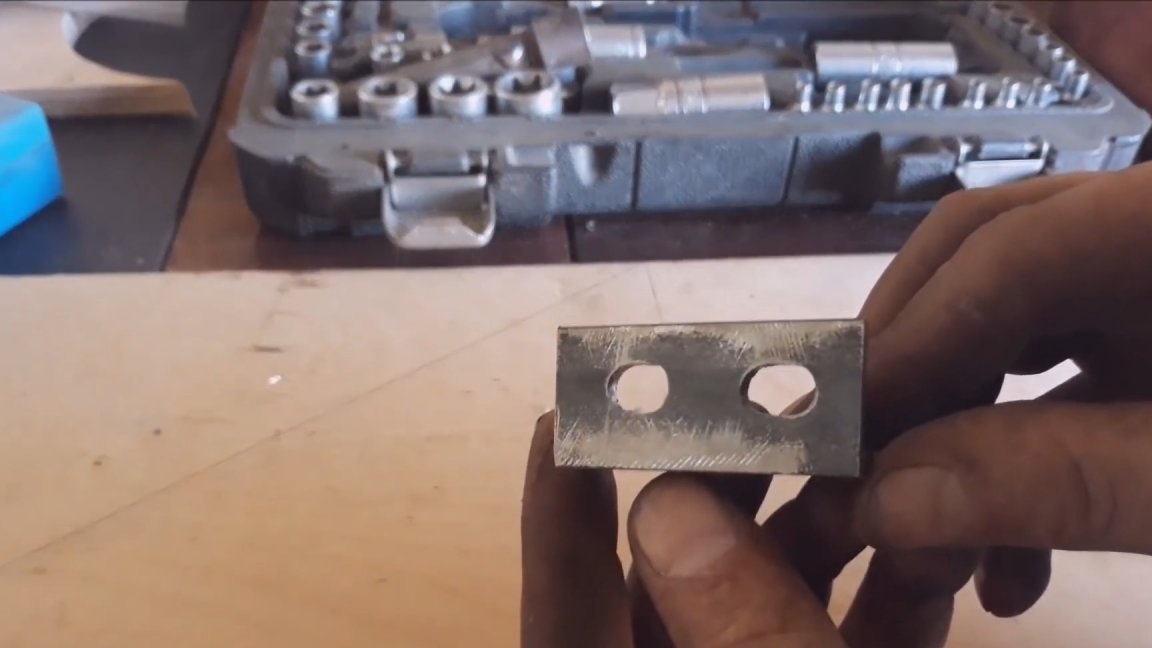
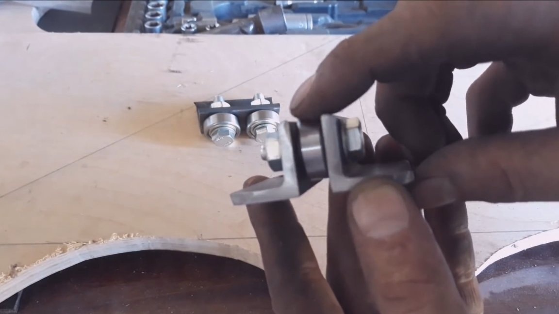
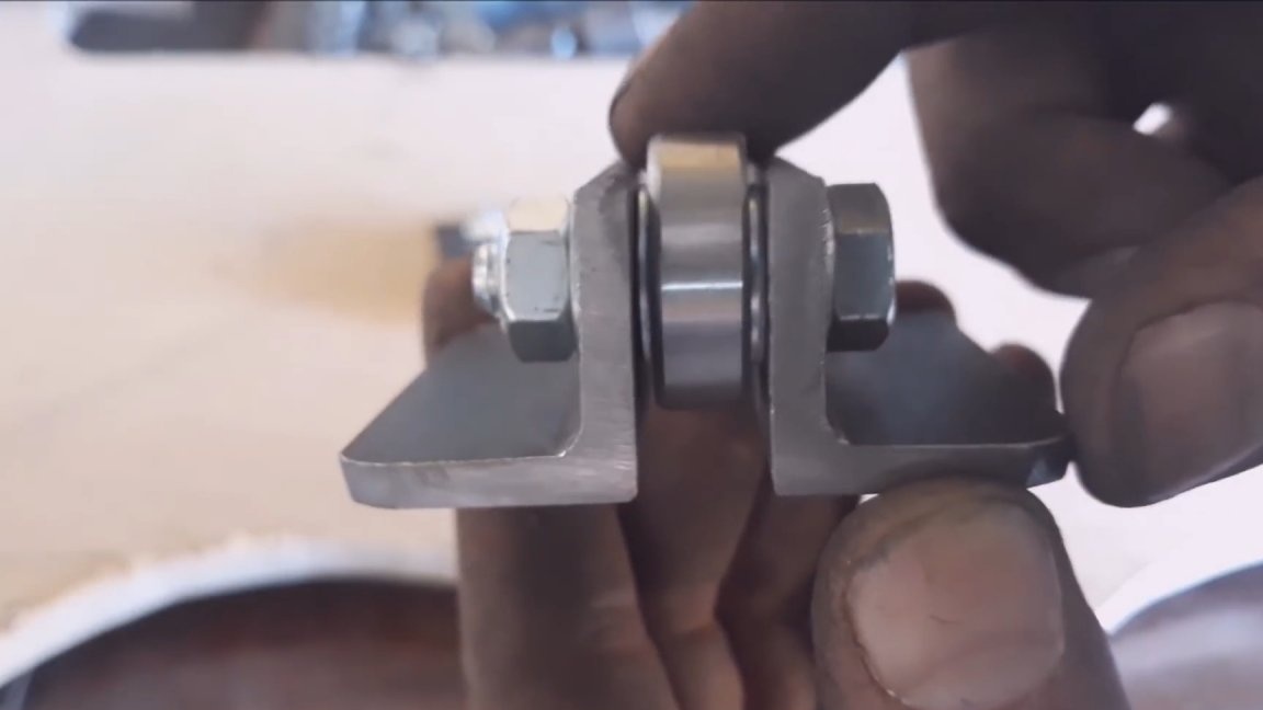
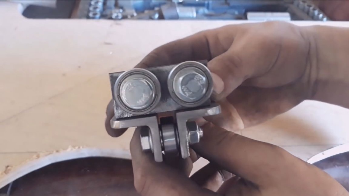
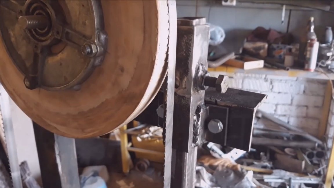
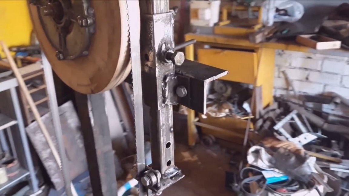
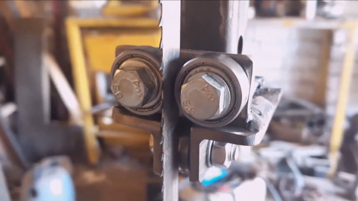
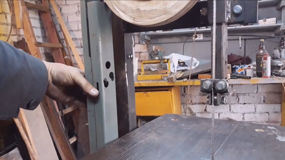
Now you need to make a node that will hold the tape in the right position. It consists of three bearings. Two of them hold the tape from the sides, the third supporting one. It does not allow the tape to fly off the wheels when sawing. I made this whole mechanism from three pieces of the corner. I drilled holes and inserted bearings with an inner diameter of 8 mm. They just sit well on the M8 bolts, the design of this unit is clearly visible in the photo. The hole for the bearings that hold the tape on the sides should be made oval. This will allow you to adjust the clearance. Also oval you need to make a hole for the rear bearing. This entire unit must be movable to adjust the height of the cut. He made it on the same principle as the movable carriage. Only instead of a tube was a profile pipe taken. I drilled a hole in the outer frame, welded a nut and screwed a bolt in there. He will fix the bar in the desired position. I also welded two corners with holes to the body. This whole structure is attached to the lower corner of the upper wheel. The holes were specially made of a larger diameter, which allowed to adjust this whole mechanism. Even to this mechanism is attached a corner that closes the tape. It performs a protective function. The same bearing unit was installed near the lower wheel under the table. Welded it to a thick plate. He is motionless.
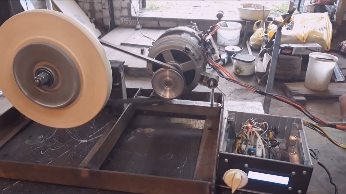
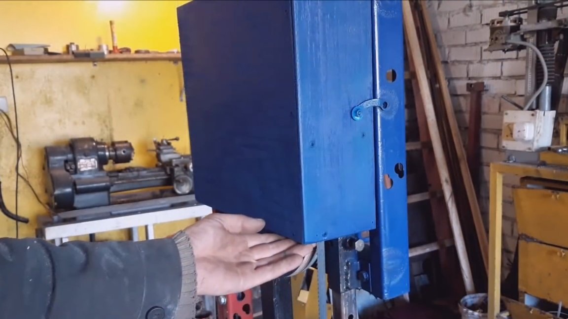
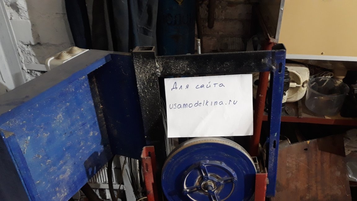
On the left side, the tape runs up and is also open. Under the arm came a p-shaped profile. He assembled the box from two pieces and secured it to a vertical rack. The box is twisted with bolts. Inside is a ribbon. Safety is important. Then I made a table. The frame for it was a 15 × 15 pipe. Note that the table frame must be made open so that the tape can be replaced. I decided to make the frame inclined, so the engine from under the table migrated to the other side. The benefit of digesting the mount is not difficult. I threw a sheet of chipboard on the table frame, after having made a cut, to thread the canvas. At the end, the cut was expanded slightly to exclude the clamping of the saw blade. The table was screwed to the frame with countersunk screws. For the upper wheel made a plywood box. A box with an engine control board is attached to it.
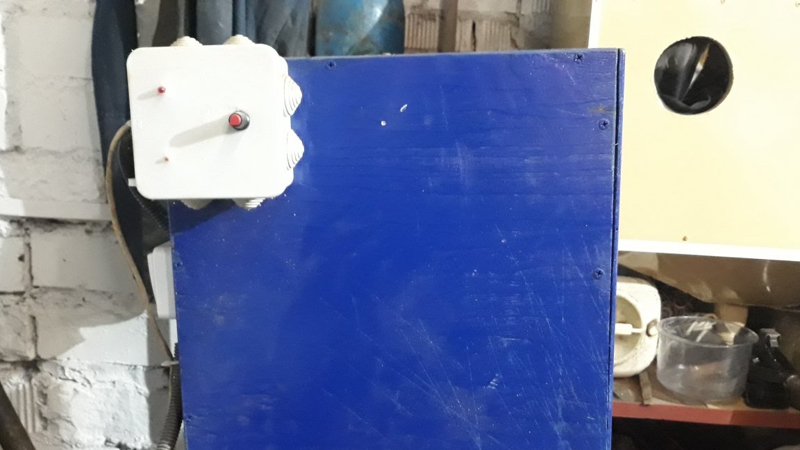
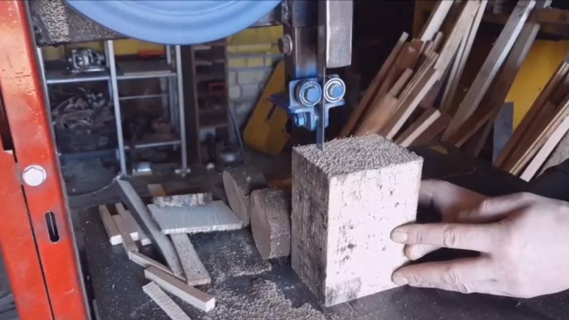
After assembly and testing, the machine was painted. The power of the motor is enough for everyday tasks. I often use it to cut slats from scraps from a large sawmill.
It is very difficult to describe all this in words. Better to see once. I will attach the video. There you can consider everything in more detail. See you again. Till!