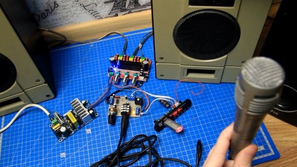
Today we will consider another project from the author of YouTube channel "Radio-Lab", namely, the assembly and connection of a microphone amplifier for karaoke.
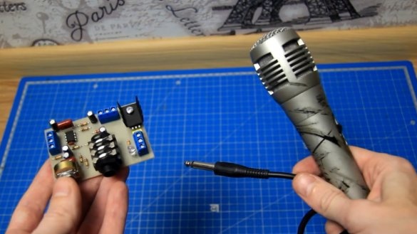
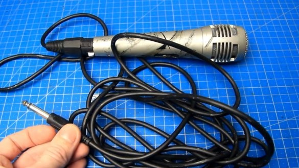
The subject will be such a microphone from a home theater of an unknown brand.
The microphone is the most ordinary, and many, I am sure, also have it. To use it to the maximum, you need to connect it, for example, to a sound amplifier. But just as it is, of course you can connect a microphone to the amplifier, but there may not be the desired result. In order for everything to work correctly, the microphone needs its own microphone amplifier, which will amplify the weak microphone signal to the required level and then the received signal can be amplified without problems with a conventional sound amplifier.
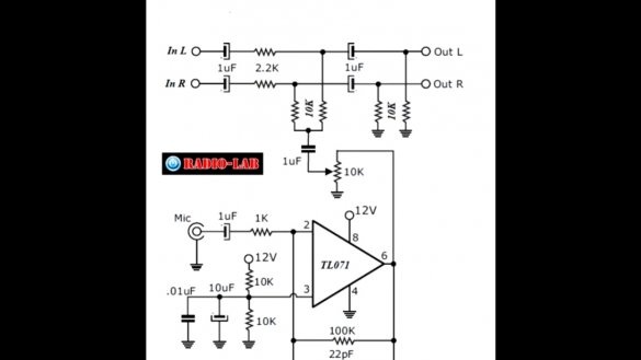
One of the options for such a microphone amplifier, we now consider. The following circuit of a microphone amplifier based on the TL071 chip was found on the Internet:
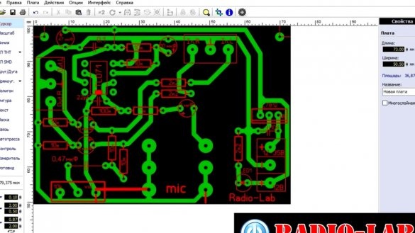
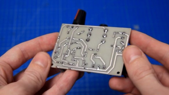
This scheme is unipolar powered. The author developed a board for the future microphone amplifier.
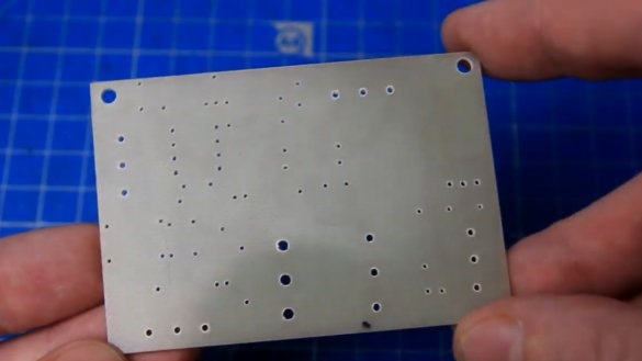
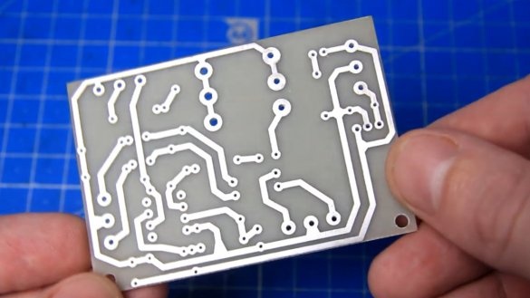
This is how the finished board of the future microphone amplifier looks like:
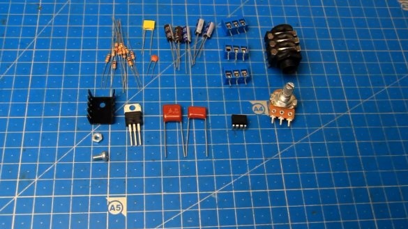
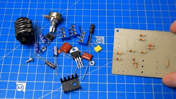
All the necessary radio components can be purchased on the radio market or from Chinese comrades with Aliexpress:
- 6.3mm socket;
- Textolite F4 for boards;
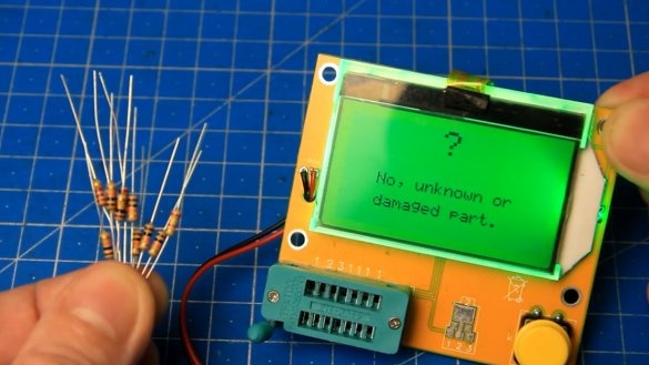
- ESR tester;
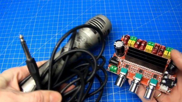
- Amplifier TPA3116D2 2.1;
- Mortise sound module;
- Linear stabilizer L7812;
- Resistors.
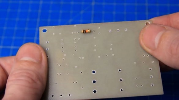
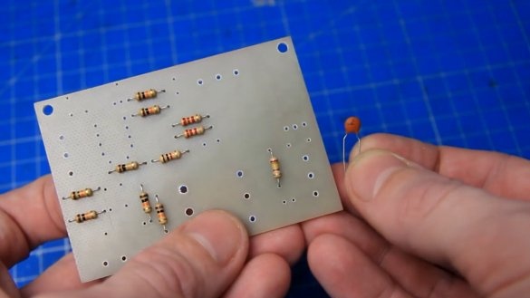
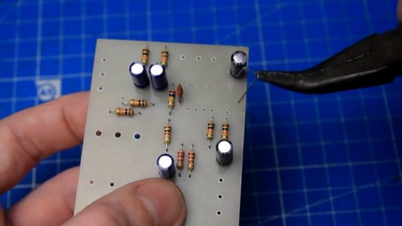
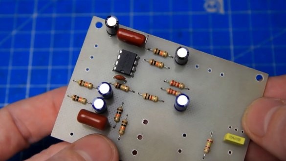
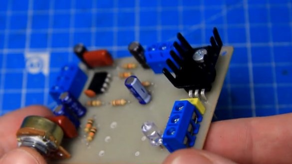
All items will need to be installed on the board. There are not many details and there should be no problems with the assembly, the main thing in this matter is not to rush. Let's start assembling the microphone amplifier with the installation of constant resistors.
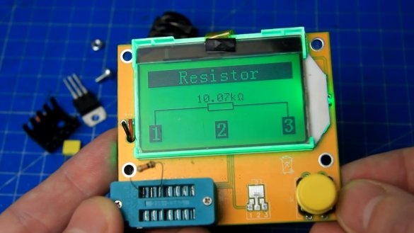
It is convenient to use such tester:
As you can see, the value of the resistor is about 10k, install it in its place.
We do the same with the rest of the resistors.
Permanent resistors installed. You could say that was the hardest part of the assembly. Next in line is a 22pF non-polar disk capacitor.
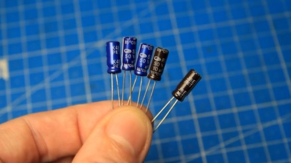
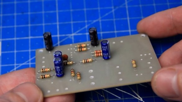
Then we install (always observing the polarity) polar electrolytic capacitors. A longer leg is a plus (+), and there is also a minus sign (-) on the body. In addition, denominations are indicated on the case.
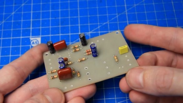
Polar capacitors in place. There is one jumper on the board, it can be made from the trimmed legs of any component, for example, a capacitor.
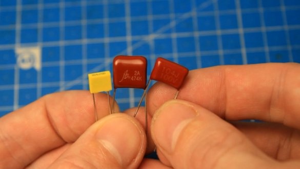
Next - film non-polar capacitors.Just set it in place.
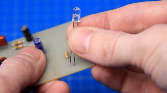
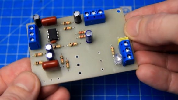
Next up is the LED. It has polarity. A longer leg is plus (+), a shorter leg is minus (-), respectively.
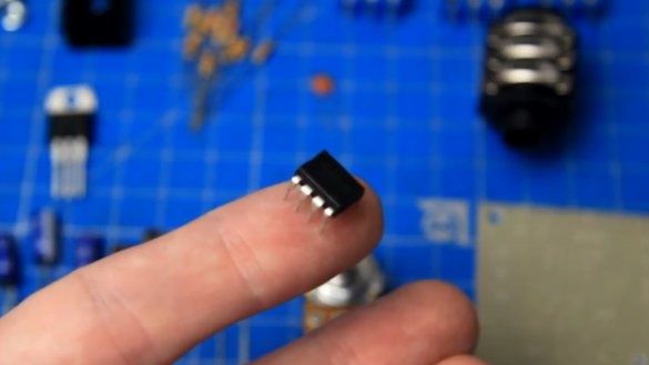
Then, using the key on the case, you need to install the chip.
Now the terminal blocks. They are the same, 3 pins.
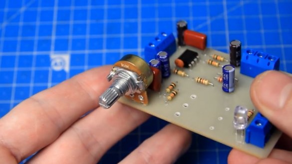
Next is a variable resistor. He is alone, at 10k.
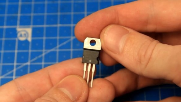
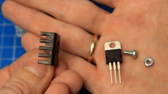
To expand the power range and functionality on the board, there is a place for installing a linear voltage stabilizer L7812 with an output of 12V.
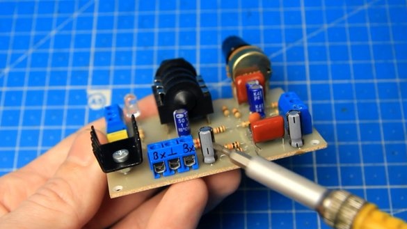
This stabilizer does not interfere, but it heats up significantly during operation. Installation of a radiator is required.
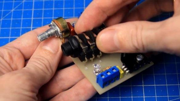
Next, seal the 6.3mm jack for connecting a microphone.
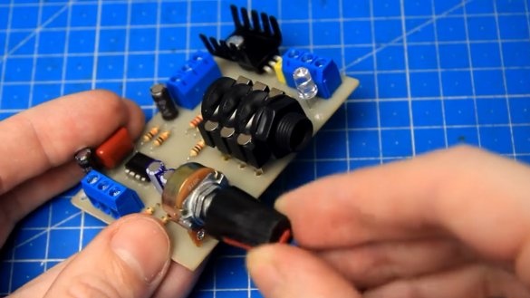
For ease of adjustment, put the knob.
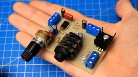
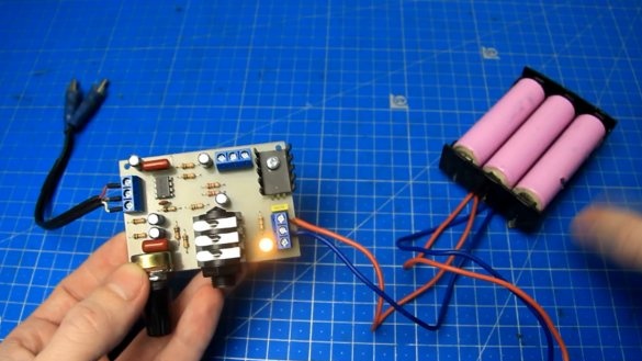
We wash the board from the flux and after the work has been done, we get a microphone amplifier, this is how it looks:
A variable resistor allows you to change the volume level of the microphone. At the back of the board are input contacts for supplying an audio signal (for example, from a mortise module or a telephone), and near the variable resistor there are output contacts for connecting, for example, to the input of a sound amplifier.
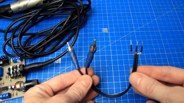
Now let's check the operation of the assembled board and check whether it will fulfill its task, namely to amplify the signal from the microphone. For the sound signal we will use here such a wire.
The microphone signals are the same for the left and right channels, in fact one mono signal. We feed the circuit from a battery with a voltage of 12V. Observing the polarity we connect the battery.
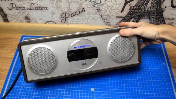
The LED is lit, therefore there is power. For tests, the author uses this column:
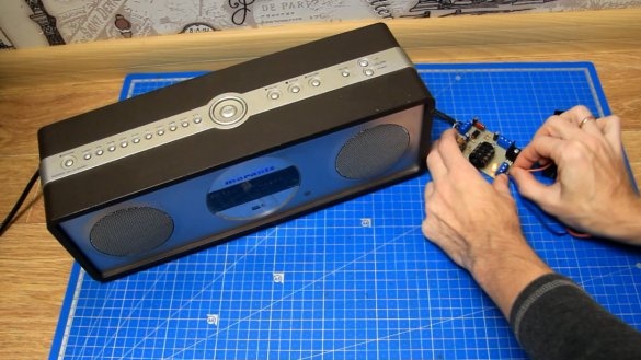
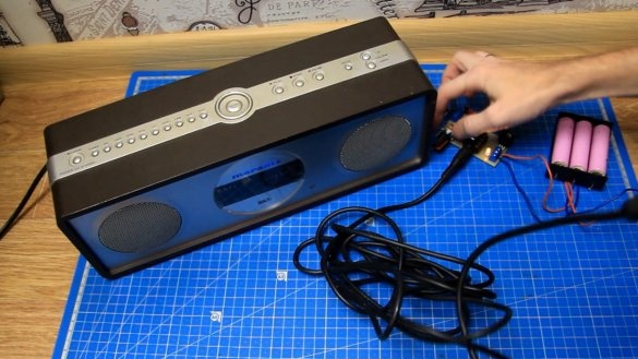
We connect the output from the microphone amplifier board to the speaker input and apply power. Now everything is ready for a performance test. We set the microphone volume on the board to the minimum position and connect the microphone.
Then we gradually increase the microphone volume (see the author’s original video for more details).
So, the assembled microphone amplifier works fine, then we will consider various possible schemes for connecting it.
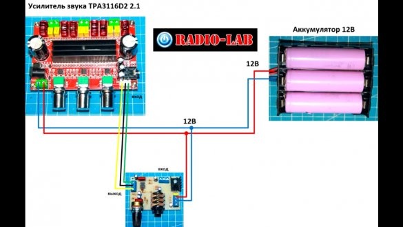
1. Connect the assembled microphone amplifier to the sound amplifier board. We connect the power wires from the 12V battery and signal wires according to the following scheme:
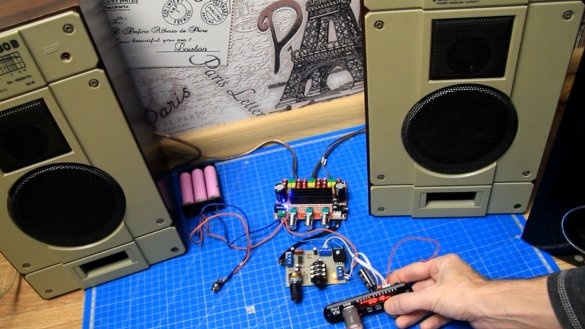
For an example, the author used a sound amplifier board 2.1 based on two TPA3116D2 microcircuits with unipolar power supply. We connect test acoustics to the sound amplifier. But the functionality of the assembled board does not end there.
2. This board can work just like a microphone amplifier, or it can superimpose a microphone signal on music, and, therefore, with its help you can add the karaoke function.
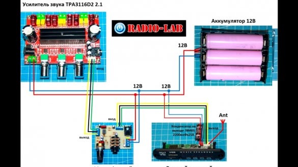
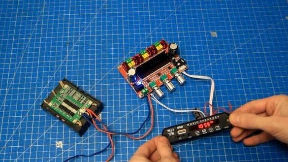
We connect a mortise sound module to the sound amplifier. Using the microphone amplifier board, you can make it possible to connect a microphone to this assembly. The microphone amplifier board is included in the gap of the signal wires between the mortise module and the sound amplifier, or between the timbral block and the sound amplifier. The power of the microphone amplifier is connected in parallel to the power terminals of the sound amplifier. The assembly will be powered by a 12V battery in this case. Here is the connection diagram:
If you do not connect a microphone, then it will be a normal sound amplifier with MP3, radio and other embedded functions.
You can also use other similar ones, for example, stereo sound amplifiers with unipolar power.
The connection is exactly the same as that of the amplifier 2.1. For amplifiers with bipolar power, the microphone amplifier board is also suitable, but in this case it must be powered from a separate power source or from the plus power arm (ground and plus), if the supply voltage allows.
Inspection with a thermal imager showed the following picture. Most of all, the L7812 stabilizer on the microphone amplifier board heated up. It is warming up, but that's fine. If the heating is strong, then you will need to screw a larger radiator.
Here's a mic amplifier board. As you can see, there is nothing complicated, and if desired, this project is quite easy to repeat. Using this board, you can assemble an amplifier with the ability to connect a microphone, you can also assemble an amplifier with the karaoke function, stationary or portable on batteries, or add the ability to connect a microphone to ready-made devices (if it is technically possible to do this). In general, the application is essentially limited only by imagination and tasks.
Try and collect. Here LINK on the board drawing. Thank you for attention. See you soon!

