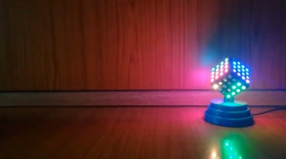
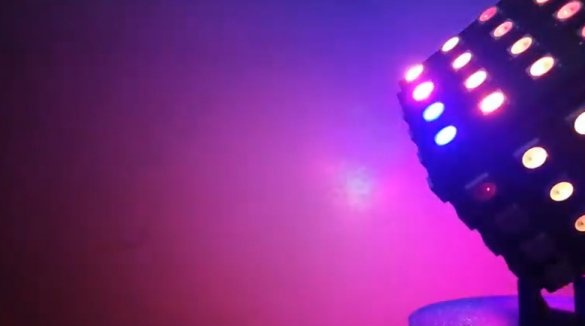
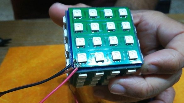
In this article, the Wizard will tell us how to make an LED mood cube using Arduino and WS2812 LEDs.
Tools and materials:
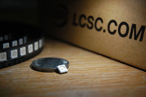
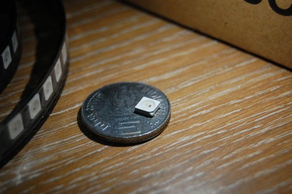
- WS2812 LEDs - 96 pcs.;
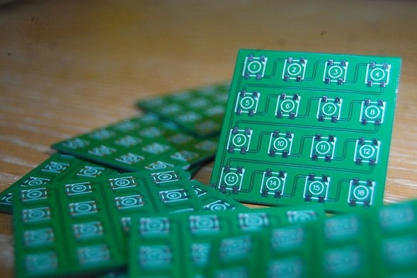
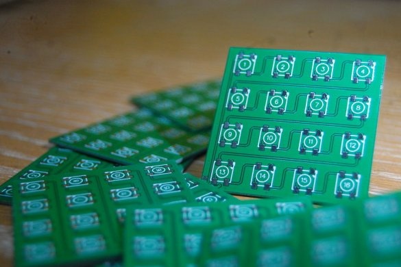
- Printed circuit boards - 6 pcs.;
-Arduino Nano;
- Power supply 5V 1A;
-Soldering accessories;
-Computer with software;
-Iron;
-3D printer;
Step One: Plan
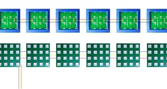
In his project, the master uses addressable WS2812 LEDs. The LEDs are connected in cascade, which means that you can control as many LEDs as needed with just one signal line / wire from the microcontroller. This makes wiring much easier.
LEDs will be controlled by Arduino Nano.
Step Two: PCB
For the design of the printed circuit board, the master used the EasyEDA program, as it is suitable for beginners.
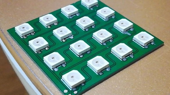
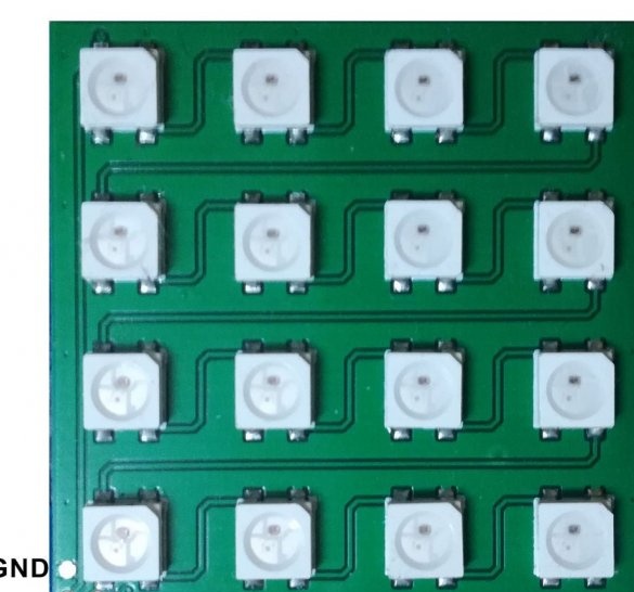
The LED has 4 contacts:
VDD - 5 V
DOUT - output signal
VSS - Earth
DIN - input signal
As mentioned earlier, the LEDs are cascaded, which means that the signal comes from the microcontroller to the first LED on the DIN pin. From the DOUT pin, the signal goes to the DIN pin of the second LED.
When designing printed circuit boards, the master planned to solder them manually, so between the LEDs he left enough space for a soldering iron.
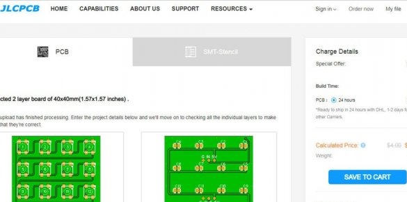
The master did not make the board himself, but ordered on JLCPCB.
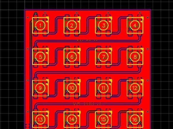
You can download the file for making the board below.
Schematic_Cube Lamp_Sheet_1_20191213095045.pdf
Step Three: Board Mounting
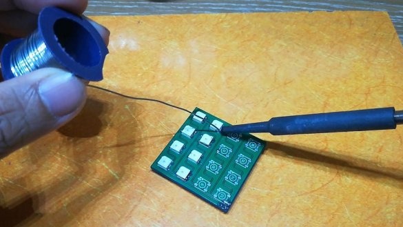
First, the master began to manually solder the LEDs one by one with a soldering iron. The result was not very good, not only was soldering the installation of 96 LEDs a laborious process, they also overheated when soldering.
Then the master decided to go the other way.
The most widely used method for soldering SMD components is called Reflow Soldering. In this method, solder paste (a mixture of solder and flux) is applied to the pads on a printed circuit board and the components are placed on it. The solder paste is then melted or “melted” by heating it in a reflow oven. This is a quick and accurate method, if everything is done correctly.
But the use of this method means that it will take a furnace for reflow, and the master did not have it.
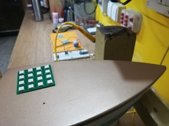
Then he remembered the project of Moritz Koenig, in which he used an old iron.
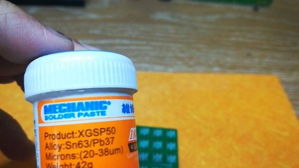
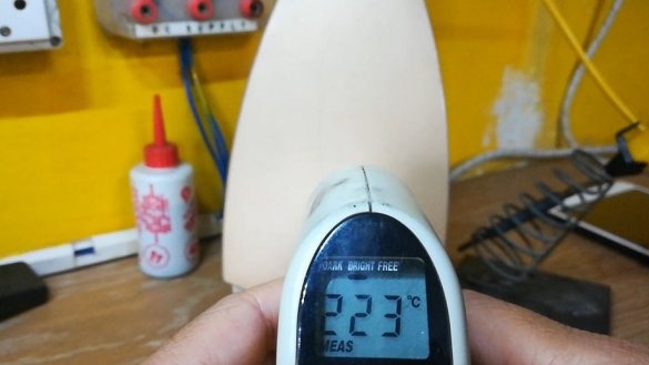
The master had an iron, the sole of which, at maximum settings, reached approximately 220 ° C. The solder paste he bought melts at 183 ° C.
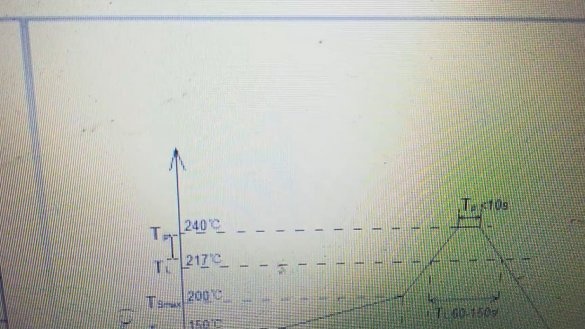
Looking at the graph of the reflow temperature from the LED table, you can see that the maximum temperature (Tp) is 240 ° C for 10 seconds. The iron does not hold out a bit, but the master decided to try.
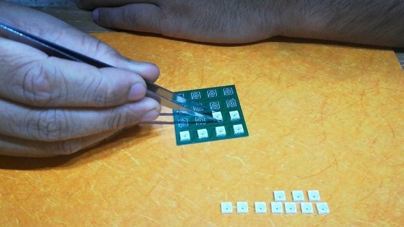
He applied the paste to the pads with a toothpick and placed the components. Then he put the board on the iron, as shown in the photo, and turned it on. When all the solder melted, he turned off the iron and removed the board. Surprisingly, everything turned out as it should.
Step Four: 3D - Print and Build a Cube
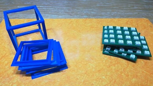
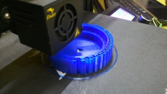
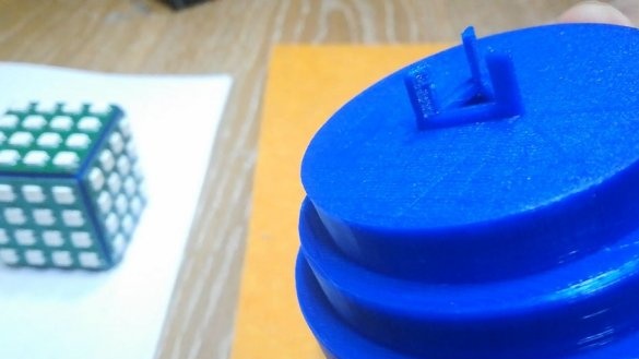
To assemble the cube, the master first printed the parts on a 3D printer. It is necessary to print the frame and six panels and the details of the base.
Files for printing can be downloaded below.
Skeleton.stl
Holder.stl
Base.stl
Stand.stl
Cover.stl
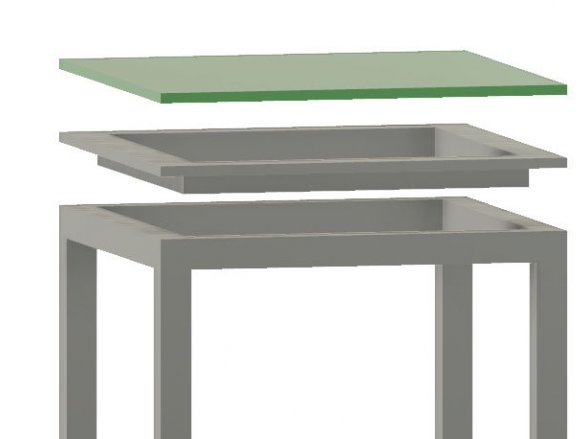
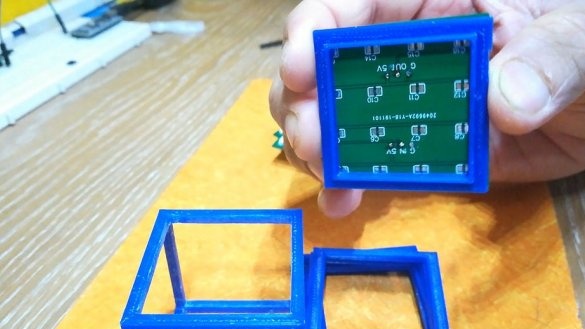
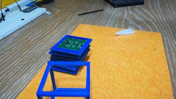
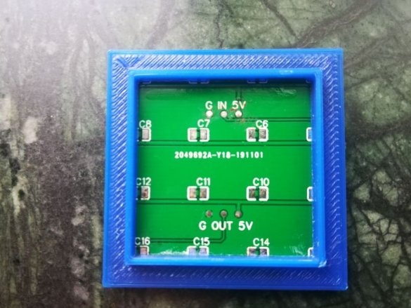
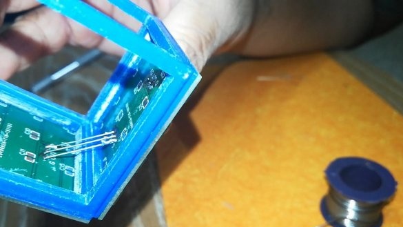
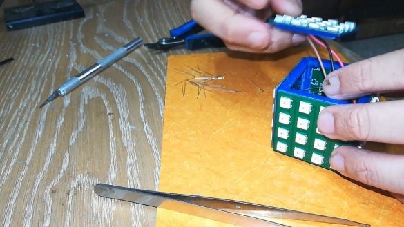
Now you need to glue the boards to the panels, and install the panels in the openings of the frame. Make installation, as in the photo.
Step Five: Arduino
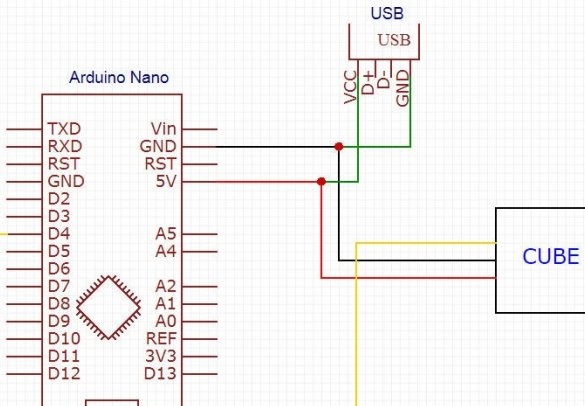
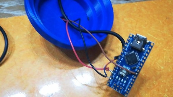
Next, the master connects the cube to the Arduino and the power supply.
Step Six: Code
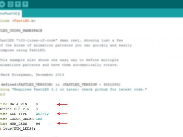
Next you need to install Fastled using the dispatcher. Open DemoReel100 from sample sketches. File> Examples> FastLED> DemoReel100.
Before downloading the code, make the following changes:
Define DATA_PIN (the pin on the Arduino to which the DIN cube is connected) to the one you selected. In this case, digital contact 4.
Define LED_TYPE as WS2812.
Set NUM_LEDS to 96.
And, click Upload.
Now you can enable the cube. In the future, the master plans to connect the ESP8266 to the Arduino and make an Internet connection. In the new firmware, it is planned to change the glow of the cube depending on the event in the author's life.
The whole process of making such a cube can be seen in the video.

